The PCB capacitor on the circuit board is one of the essential passive components we employ during the design process. It affects a circuit's performance and quality.
During PCB assembly and manufacture, accurate knowledge of the properties and characteristics of capacitors guarantees success in designing your capacitor circuit board.
Additionally, a capacitor in your gadget may be damaged due to too much heat and voltage.
In that case, it requires replacement, which you can do alone.
This article elaborates more about capacitors, from their fundamentals to assembly on the PCB(Printed Circuit Board).
Contents
- What Is a PCB Capacitor?
- How Do Capacitors on Circuit Boards Work?
- Types of Capacitors
- Ceramic Capacitors
- Film Capacitors
- Electrolytic Capacitors
- Mica Capacitors
- PCB Capacitor Markings
- Measuring PCB Capacitance
- Capacitors in High-Frequency PCBs
- The Role Embedded Capacitors Play in PCB Design
- How To Reduce Parasitic Capacitance in Circuit Board Layout
- Tips on How To Place Your PCB Bypass Capacitor
- Factors To Consider When Choosing a Capacitor on a Circuit Board
- Troubleshooting Printed Circuit Board Capacitor Issues
- How To Replace a Capacitor on a Circuit Board
- Step 1: When Do You Replace a Capacitor?
- Step 2: Arrange the Tools for Capacitor Replacement
- Step 3: Access the Damaged Capacitor
- Step 4: Remove the Damaged Capacitor
- Step 5: Install the New Capacitor
- Risks/Hazards of Printed Circuit Board Capacitors
- Exposure to Hazardous Materials
- Electric Shock
- Fire
- Handling PCB Capacitors
- Storage of PCB Capacitors
- Disposing of Your PCB Capacitor
- Summary
What Is a PCB Capacitor?
A PCB capacitor is an electronic component on a printed circuit board that stores an electrical charge and discharges it into a circuit.
It contributes to the smooth operation of an electronic device by controlling the electrical flow throughout the PCB.
PCB Capacitance refers to how much electric energy a capacitor can carry.
In its most basic form, a PCB capacitor consists of two conducting plates with a dielectric material.
There are different types of capacitors that have numerous uses. They can swiftly discharge their charge, which is common in lasers and flashes with capacitive sensing devices.
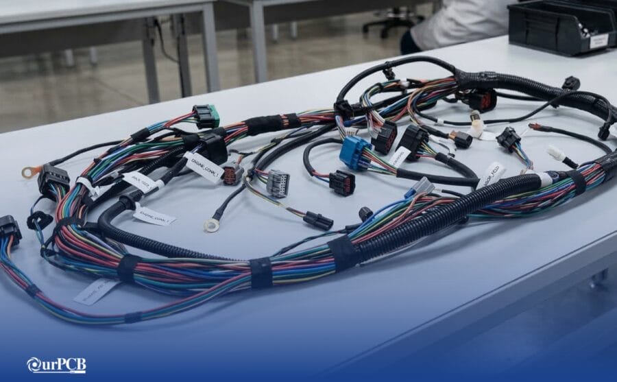
Capacitors on Circuit Board
How Do Capacitors on Circuit Boards Work?
Capacitors on a circuit board require a charge to function. The first plate of the PCB capacitor accepts electrical current.
The charge builds up on the conductor causing electric charge accumulation on the electrodes.
As more electrons accumulate, the first metal plate becomes negatively charged.
Extra electrons then move to the adjacent plate. The result is a positive charge on the second plate.
The electrons on the electrodes do attempt to combine. Nevertheless, the insulator between the two plates stops this from happening.
The dielectric is a non-conductive material that impedes the mobility of the charge from traveling between the conductors.
The two metallic plates keep charging as they store electric charge in the capacitor.
Eventually, the metal plates will lose their capacity to hold a charge.
All of the electrons in the capacitor will discharge if the PCB has a conduit for the electrical charge’s movement.
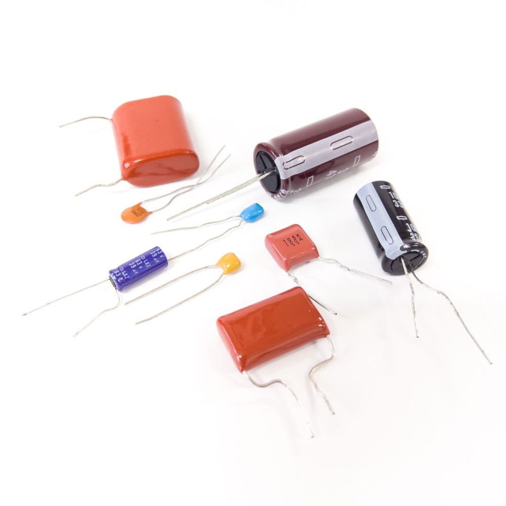
Different types of capacitors
Types of Capacitors
You can categorize capacitors into two — fixed or variable. Fixed capacitors have fixed capacitance values, while variable capacitors have varying ones.
Furthermore, fixed capacitors contain non-polarized and polarized capacitors, while the variable group has tuning and trimming capacitors.
Here is a basic summary of the capacitors' different types and characteristics.
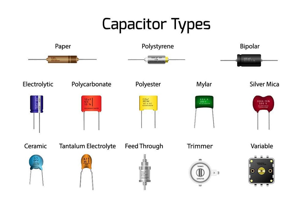
Types of Capacitors
Ceramic Capacitors
Ceramic capacitors have their insulating material made of ceramic material. They have a low capacitance value. Typically, this value lies between 1F to 1µF.
These capacitors leak less current and have a high dielectric constant. Ceramic capacitors are helpful in various applications, including RF and audio.
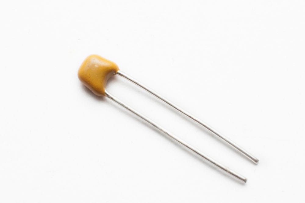
The ceramic capacitor used in electronic (generic capacitor)
Film Capacitors
Film capacitors come in several varieties: polyester, metalized, polypropylene, PTE, and polystyrene.
These capacitors have a high insulation resistance, good temperature characteristics, and no dielectric loss. The film capacitors have low inductance, are stable, and are affordable.
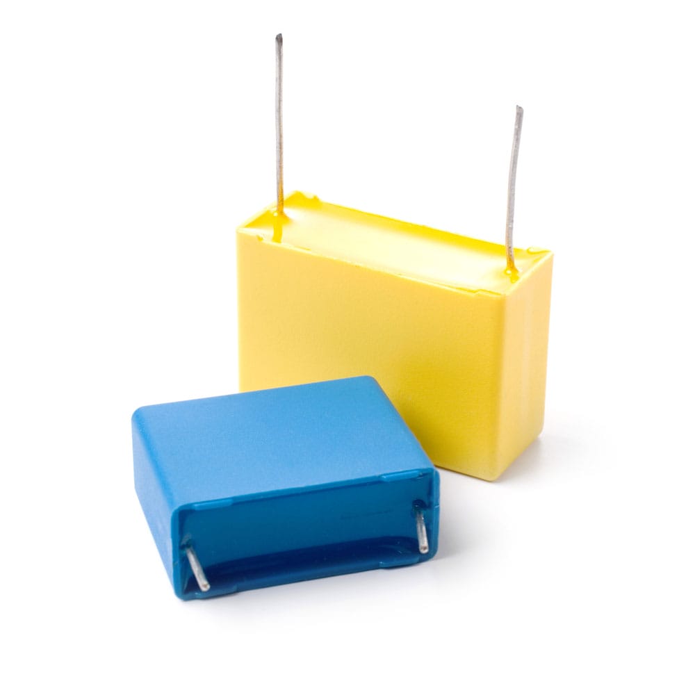 Two film capacitors
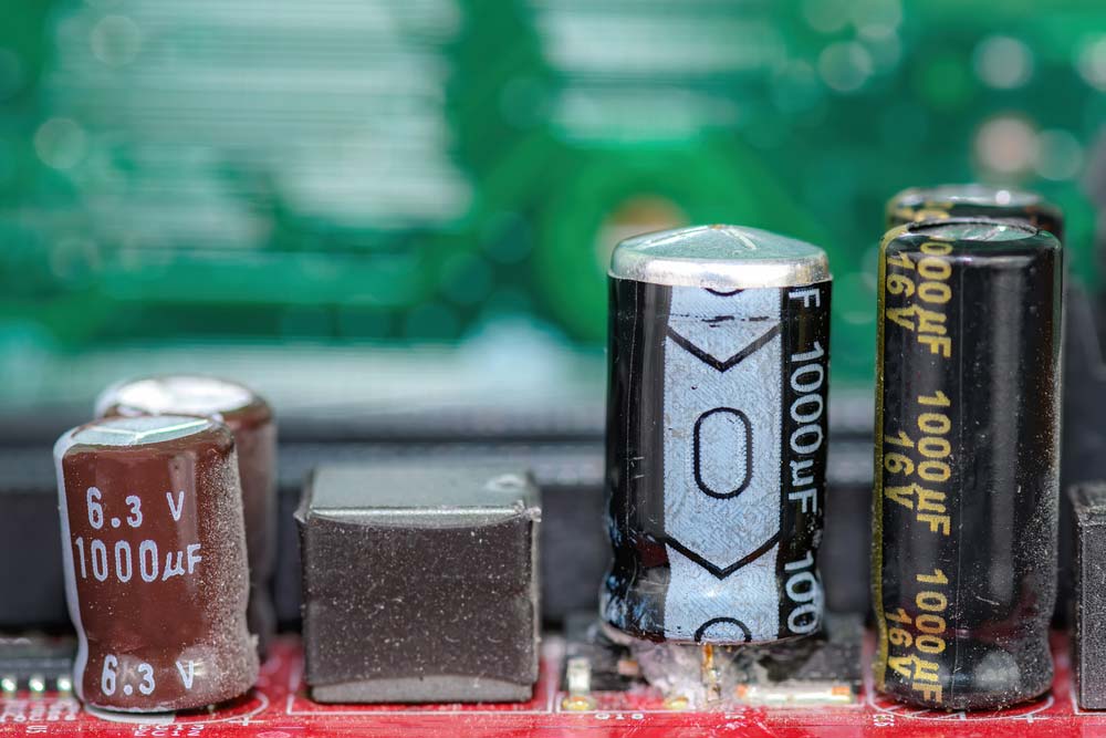
Electrolytic Capacitors
Visually, these capacitors resemble small tin cans. Electrolytic capacitors are common in circuits that require larger capacitance. It is because they store a lot of electric currents.
The dielectric material is a thin layer of oxide held in small tins.
These are polar capacitors and thus function when wired appropriately; else risk explosion when wired differently.
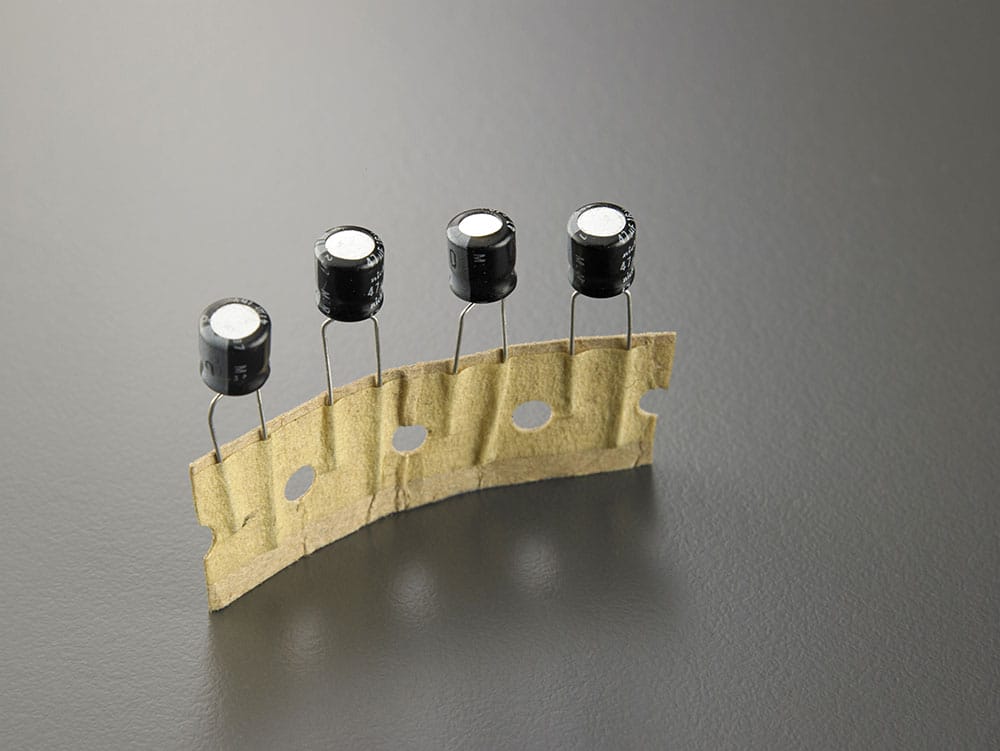
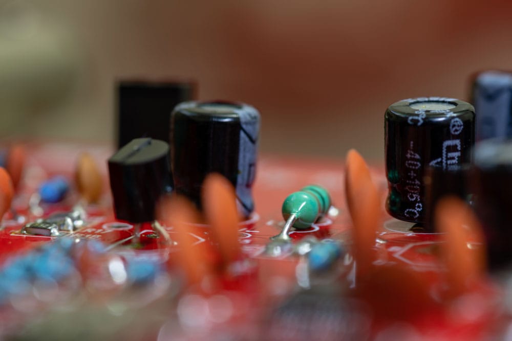
Electrolytic capacitors
Mica Capacitors
The silver mica capacitors consist of metal-coated mica sheets and epoxy-encased to protect the environment.
Mica capacitors are essential for a PCB design when compactness, temperature stability, and precision are critical.
They have a low loss of electric charge and are frequently employed at high frequencies.
They are also exceptionally stable chemically, electrically, and physically, thanks to their unique crystalline structure, typically layered.
PCB Capacitor Markings
A capacitor’s markings indicate its operating parameters and specifications, and these values are vital to know during PCB assembly and testing. They include the following.
- Capacitance Value: The capacitance value is a core marking because it indicates the device’s capabilities (charge it can store). This marking can be in picofarads, microfarads, or nanofarads, and manufacturers usually use numbers with decimal points and multipliers to indicate this value.
- Voltage Rating: Capacitors have a maximum operating voltage indicated in voltage units using the format (whole number/V/fractional number). For instance, 5.5V will be 5V5.
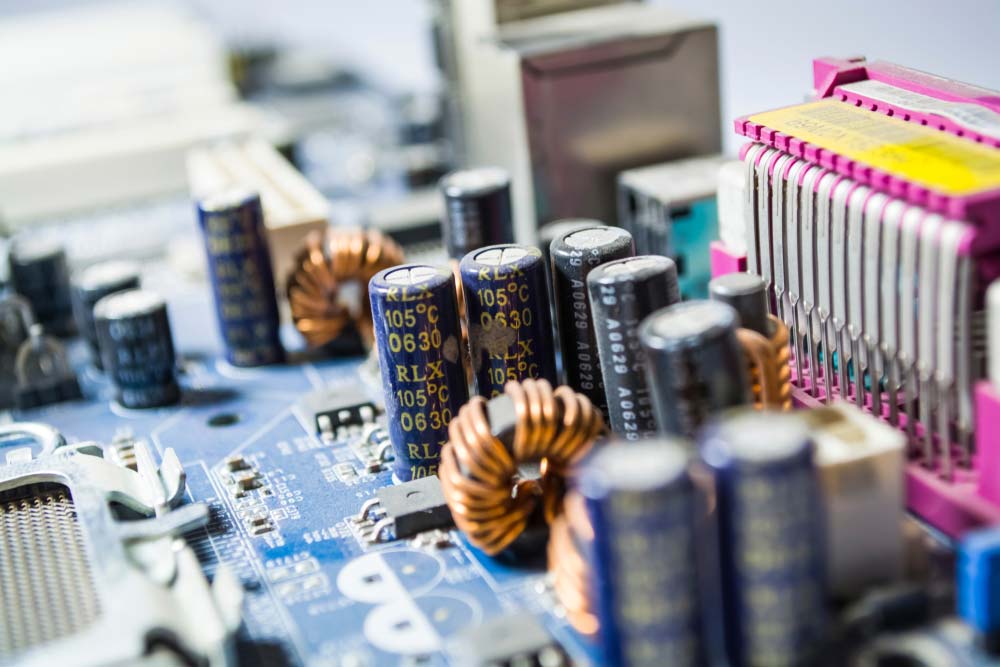
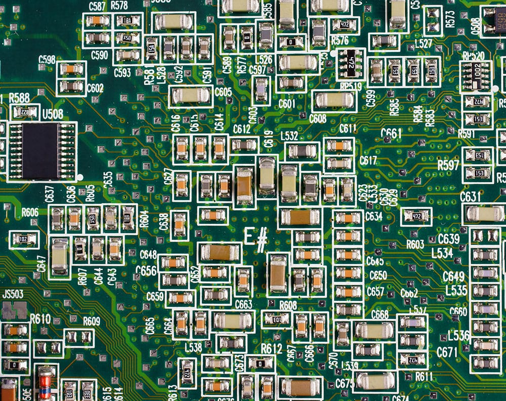
Capacitors mounted on a PCB (note the markings)
- Tolerance: This value indicates the allowable variance in percentages. Typical markings include +/-1%, +/-5%, and +/-10%.
- Temperature Coefficient: Temperature changes affect the capacitance value, and this coefficient marking indicates the maximum capacitance change over a specified range.
- Date Code: Capacitors often have their date of manufacture or batch date, with the format varying depending on the manufacturer.
- Polarity: Polarized capacitors must have positive and negative lead markings to ensure correct orientation during installation or testing.
- Logo: Capacitors have manufacturer logos for branding, sometimes accompanied by the part number.
Depending on the manufacturer, the capacitor can also have the insulating material, ripple current, and lifetime hours marked on the device.
Measuring PCB Capacitance
Each capacitor can hold a specific amount of charge, which is its capacitance. This charge capacity increases as you broaden the conductor’s surface area, meaning the larger the device, the higher its capacitance.The base unit for measuring capacitance is Farads, but one Farad holds a lot of energy. Therefore, PCB capacitors usually have their capacitance value marked in microfarads, picofarads, or nanofarads because they are tiny and hold little charge.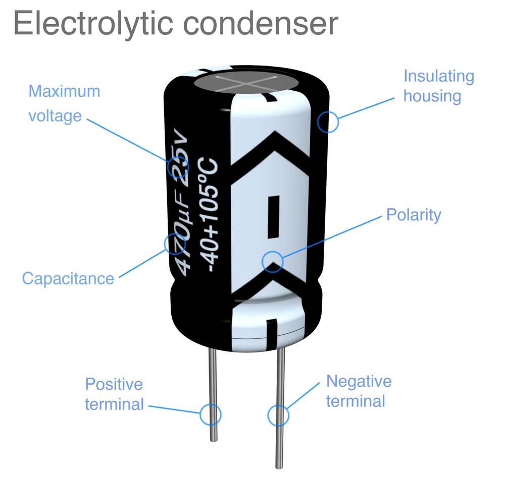
A capacitor’s capacitance value given in microfarads (uF)
To calculate the amount of charge a capacitor holds, you use the formula Q=CV, where Q is the total charge, C is the capacitance value marked on the device, and V is the applied voltage. Therefore, a power supply voltage change will affect the stored charge value.
Capacitors in High-Frequency PCBs
You can predict a capacitor’s behavior when operating at low frequencies, but they portray non-ideal behavior at high frequencies. Use these tips to ensure stable operation by avoiding behaviors like ESL and self-resonance.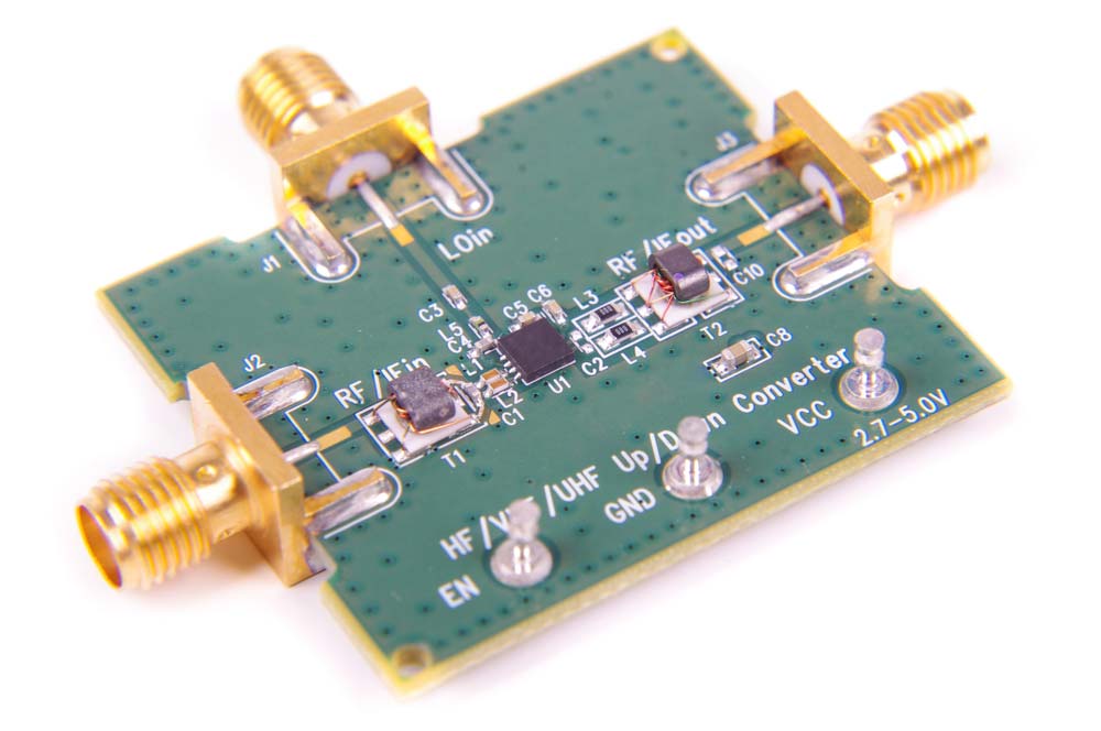
A high-frequency PCB
- Instead of electrolytes, use ceramic caps or ESR films to help filter high-frequency power-rail noise.
- Tiny case sizes have a lower ESL, with chip caps being better than Lead
- Reduce trace lengths and return paths to the ground plane
- Avoid large loop areas to prevent parasitic inductance
- Simulate the circuit using S-parameter models
- Test for ringing and other frequency-dependent issues during prototyping
- The distance between capacitor pads on the PCB affects resonant frequency. Keep that in mind.
- If the capacitor operates near the self-resonant frequency, characterize its impedance.
The Role Embedded Capacitors Play in PCB Design
Embedded capacitors have greater capabilities than conventional capacitors. Their small sizes are ideal for use as PCB surface mount capacitors.
During production, thin dielectric material fixes between two layers of copper.
The epoxy resin then laminates the copper foils together. It makes the dielectric material in embedded capacitors have a high capacitance density.
Embedded capacitors have automated assembly and low spurious inductance. They function as decoupling capacitors and have incredibly short electrical channels.
Besides, these capacitors cut power bus noise and reduce electromagnetic interference (EMI). In this way, parasitic capacitance and inductance are minimal.
Embedded capacitors are useful for telecommunications, computing, medical, and mobile devices. They function as power supply systems filters, which minimize free capacitance.
How To Reduce Parasitic Capacitance in Circuit Board Layout
Parasitic capacitance is prominent between conductors on PCB.
It is due to the high-frequency signals passing through the circuit board.
The stray capacitance then introduces EMI, which propagates down to adjacent traces.
The following ways come in handy in avoiding stray capacitance;
- You can use a Faraday shield between traces. A guard ring reduces the capacitive effect between two traces.
- You can also increase the space between adjacent traces. You can apply the 2W or 3W rule.
- Additionally, use low permittivity dielectric materials since they produce less stray capacitance in the circuit.
- Avoid routing the traces in parallel, as this leaves a maximum area between the two traces, causing maximum capacitance between the traces.
Special Offer: Get $100 off your order!
Email [email protected] to get started!
Tips on How To Place Your PCB Bypass Capacitor
One of the essential steps in the design process is the placement of the bypass capacitors.
Note that the wrong placement of the bypass capacitors entirely undermines their performance.
Here are some tips on how you should place your PCB bypass capacitors.
- It would be best if you fixed the PCB bypass capacitors under the pads of top-side SMD components. This aids in creating more room for fanout traces and vias.
- When dealing with larger non-polarized capacitors, you should arrange them in ascending value order next to the pin.
- For devices with numerous power pins, you need at least one bypass capacitor for each power pin.
- Lastly, when installing bypass capacitors, always refer to the schematic because many logic input pins on digital devices are "tied high."
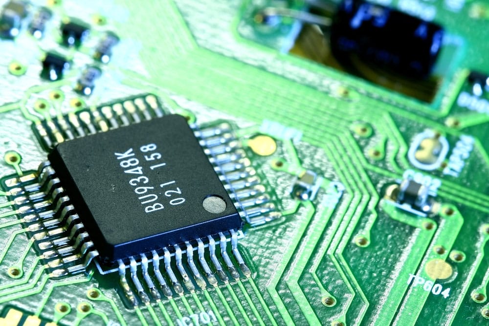
SMD circuit board
Factors To Consider When Choosing a Capacitor on a Circuit Board
- The lifespan of a capacitor is the period during which the capacitor will continue to function normally and deliver capacitance as intended.
- Voltage stress: Higher (than rated) voltages could harm capacitors. Thus, a capacitor should have a voltage buffer of 50% more than the anticipated voltage drop.
- The dielectric type material in the capacitor: A capacitor's dielectric material dictates its capacitance and thermal stability.
- Working temperature range of the capacitor: It is generally advisable to consider a buffer temperature of 50% of the maximum ambient temperature.
- Tolerance: The tolerance value shows how far a capacitor can deviate from its nominal value in both directions.
Troubleshooting Printed Circuit Board Capacitor Issues
Capacitors on PCBs can fail and exhibit either of these issues if defective or damaged.
- Low internal resistance: Indicates an internal short circuit. Replace it with a low-resistance capacitor.
- High resistance or zero continuity: Open circuit
- Bulging, cracking, drying out, or fluid leakages in electrolytic capacitors: Indicates the end-of-life (needs a replacement)
A bulged capacitor on a PCB
- Excessively high discharge voltage when unpowered: Leaking dielectric
- Low capacitance: Worn-out dielectric
- Overheating: Ripple current or excessive ESR. Replace it with a capacitor rated for high ripple current.
How To Replace a Capacitor on a Circuit Board
Step 1: When Do You Replace a Capacitor?
A blown-out capacitor may cause system failure due to component failure. Typical signs of a blown capacitor include:
- The device won't switch on
- It intermittently turns on and off
- The screen is flickering or distorted
It is worthwhile to take a few minutes to examine your circuit board capacitors if you are experiencing any of these problems. Most importantly, turn off and unplug your device from the power!
Step 2: Arrange the Tools for Capacitor Replacement
The following tools are essential for capacitor replacement:
- Screwdriver
- Soldering iron
- Replacement capacitors
- Soldering wick
Step 3: Access the Damaged Capacitor
Open the electronic casing with your screwdriver to access the circuit board. To open the case, you need to locate numerous screws and tabs.
The top of a blown-out or damaged capacitor will be somewhat curved outwards in a convex form. Check out these signs as they refer to a blown-out capacitor.
Step 4: Remove the Damaged Capacitor
Once you locate the blown-out capacitor, apply a soldering braid to the base of the leads. Push the heated soldering iron against the braid when it is wholly heated to get the solder to heat up and get drawn into the braid.
Remove the capacitor from the circuit board by pulling until the leads of the capacitor are free of solder. Remove residual solder from the circuit board's contact points using a soldering wick.
Remove a damaged capacitor on a circuit board.
Step 5: Install the New Capacitor
Installing the new capacitor requires trimming the new capacitor's leads to make them even and sit at a similar height to the previous capacitor. Then place the leads of the new capacitor in the holes where the old capacitor formerly stood.
Consequently, place the soldering iron's tip directly onto the joint on the circuit board's back. Press the wire lead through the hole as soon as the tip of the iron touches the hole, then take it out. The old solder joint will harden and secure the new portion inside of it.
Risks/Hazards of Printed Circuit Board Capacitors
Exposure to Hazardous Materials
Capacitors can have toxic powders or electrolytes that can leak when the device fails. These hazardous materials harm the environment and your health, so you should handle them carefully by wearing personal protection equipment.
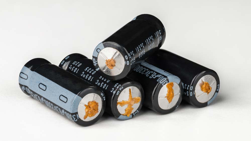
Leaking aluminum electrolytic capacitors
Electric Shock
Capacitors can store a large charge at high voltages, which can shock you if you touch or contact both terminals. The safe practice is to discharge the device before handling it and ensure no exposed wires are coming from it.
Fire
The high electrical current flowing into the capacitor’s plates can also cause fires if you exceed the power rating, fail to cool the device adequately, overload it, or incorrectly connect the polarized type. It can even explode, creating a dangerous situation.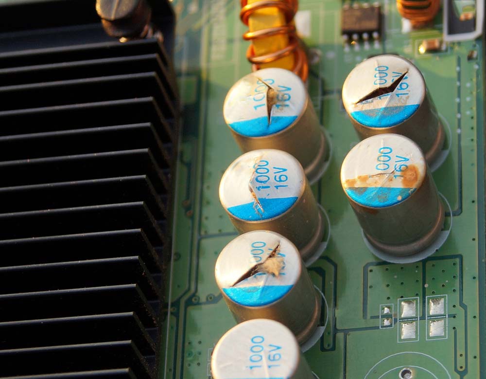
Damaged capacitors on a video card
Handling PCB Capacitors
- Wear protection equipment like gloves and glasses before handling the capacitor.
- Ensure you ground the equipment you’ll use to touch the capacitors (like gloves)
- Consider the electronic discharge risk after power disconnection. We recommend connecting a bleeder resistor across the terminals to discharge the device safely. Its resistance should be high enough to prevent current leakages into the circuit and low enough to discharge the device.
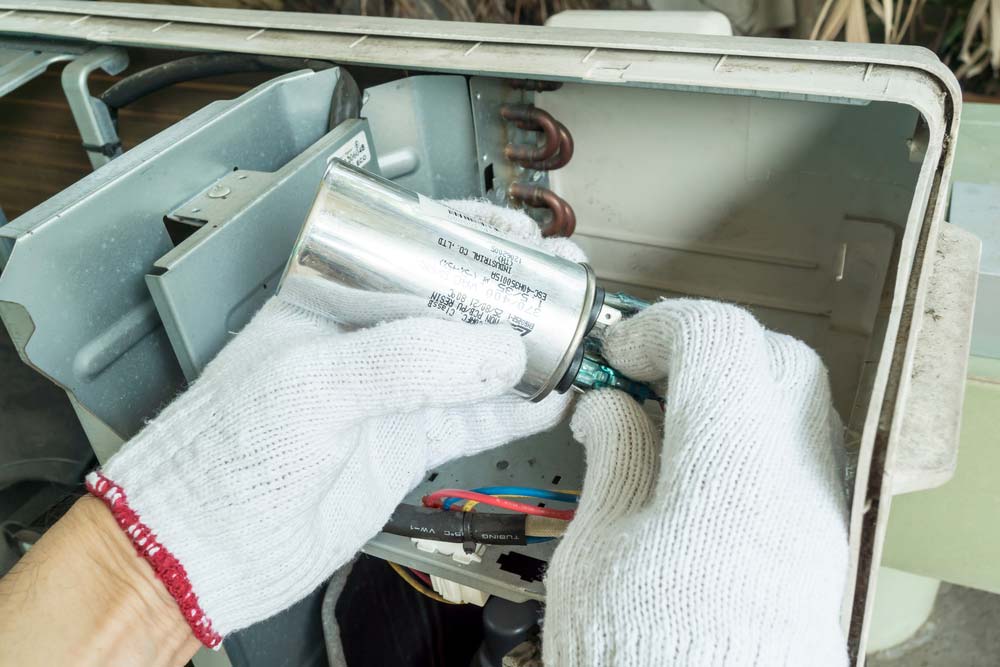 A technician handling an air conditioner’s capacitor while wearing gloves
- Ensure there are no exposed wires from the capacitor.
- Check the capacitor’s voltage and capacitance values and ensure they match the circuit’s requirements.
- Ensure the capacitor’s polarity or orientation is correct before inserting it into the circuit.
- Check the terminal dimensions, surface-mount land pattern size, and hole pitch (radial lead capacitors) to prevent terminal stress, which weakens them.
- Avoid placing excessive mounting pressure on the device to prevent high-leakage currents, shorting, or disconnections.
- Install capacitors that can withstand higher temperatures than the heat produced in that section of the board. High temperatures degrade capacitors by cutting the lifespan by half for every 10°C increase above the rated limit.
- Avoid sharp-angle cutters when handling radial-capacitor leads to prevent stressing and damaging them.
Storage of PCB Capacitors
Circuit board capacitors are humidity and temperature-sensitive, so you must store them in controlled environments to avoid damaging or reducing their performance.
Magnetic fields can also affect a capacitor’s performance when storing charge, so keep the device in RFI/EMI shielding bags.
When handling the components, avoid touching them using your bare hands. Use the manufacturer or regulatory-approved containers to hold the devices during storage and in transit.
And remember to label the devices correctly for easy identification or to know their properties.
Disposing of Your PCB Capacitor
Crushing and shredding are no longer acceptable substitutes for disposing of PCB capacitors. Leaky PCB capacitors are harmful to the environment.
Therefore, disposing of your PCB circuit boards requires direct disposal at a TSCA- or Hazardous Waste-approved disposal facility. A transporter permitted to haul PCB waste will pick them up for proper disposal.
PCB board and electronic components
Summary
Although people overlook passive components in electronic circuit boards, they are essential for PCB assembly and manufacture. Particularly for semiconductors that run on direct current, capacitors are essential companions.
In case you have any questions, please get in touch with us on our website.
Special Offer: Get $100 off your order!
Email [email protected] to get started!