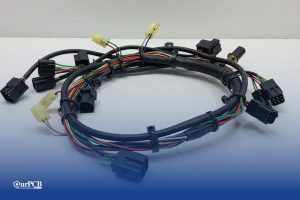
Top 10 Classic Car Wiring Harness Manufacturers | Full Guide
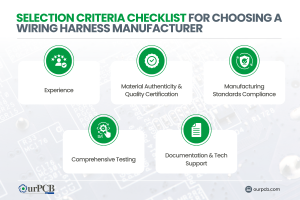
Finding the right wiring harness manufacturer for your vintage ride can be a real headache. Those beautiful old machines need special wiring that looks period-correct

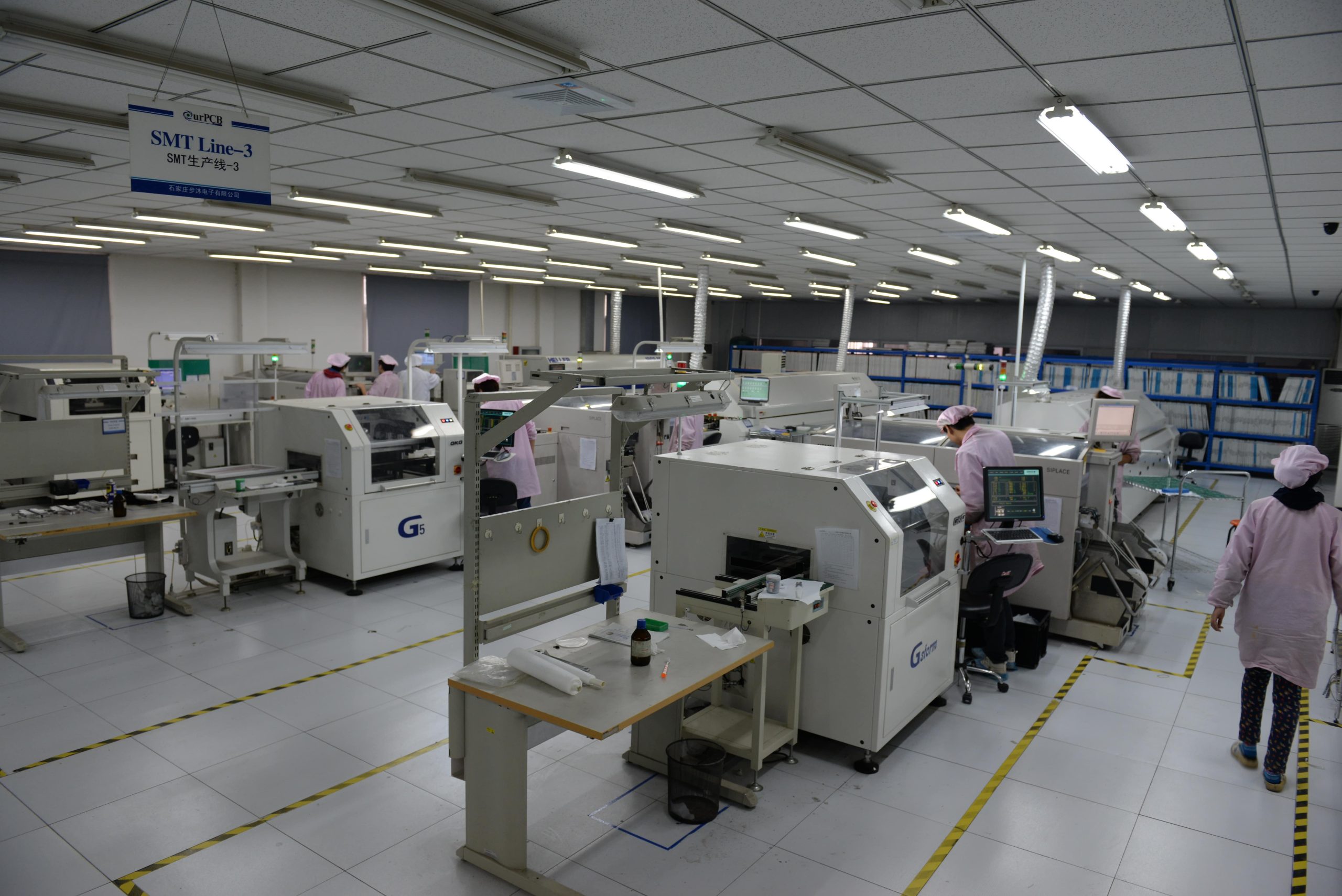
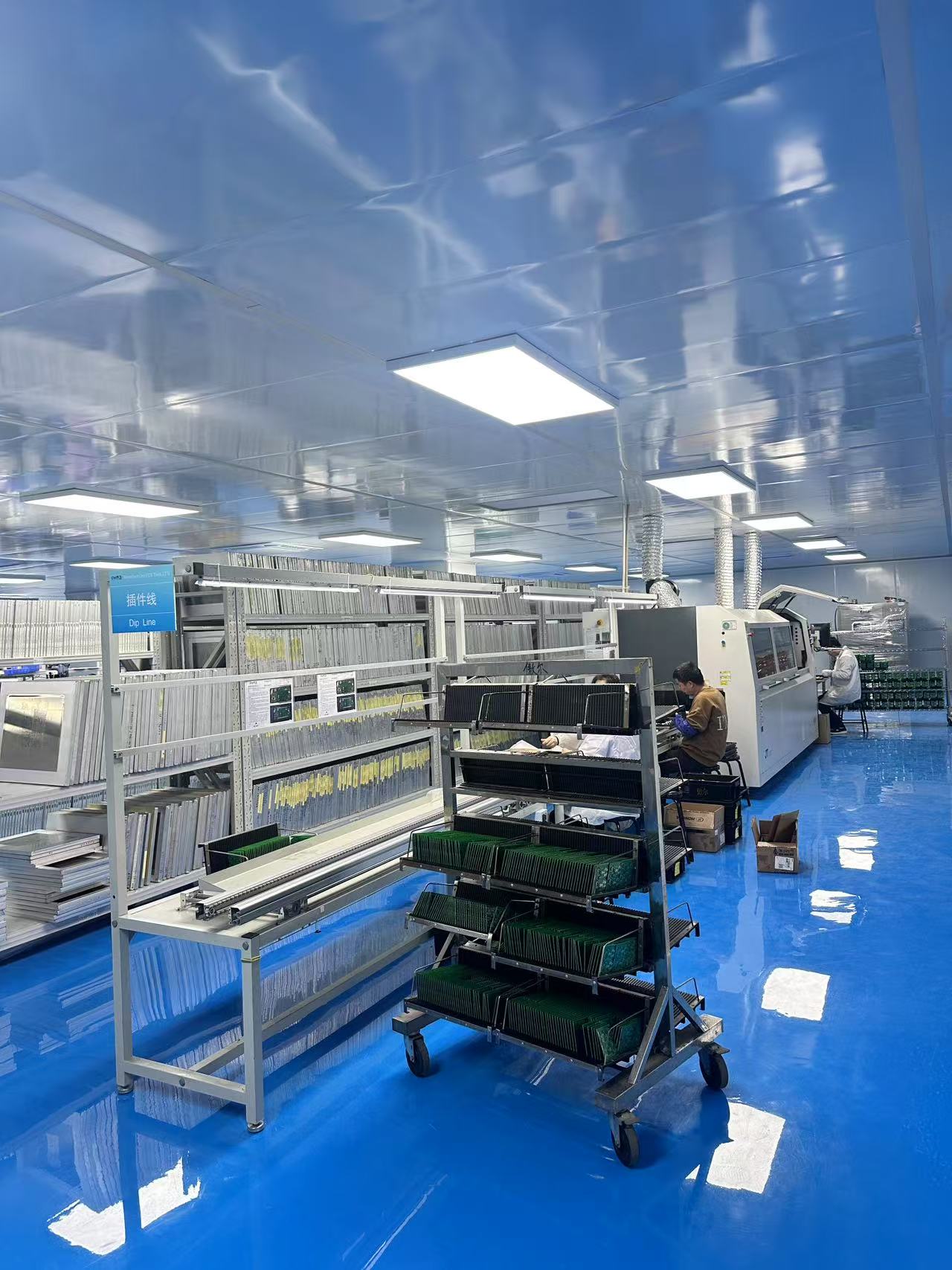
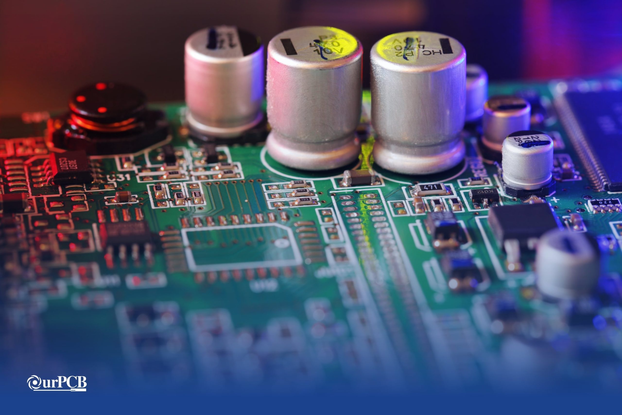
OurPCB specializes in Printed Circuit Board Assembly (PCBA) using Surface Mount Technology (SMT) for precision and efficiency. SMT places compact components directly on the PCB, reducing size and weight while improving performance. With advanced technology and expertise, OurPCB delivers high-quality, reliable PCB assemblies tailored to your needs .


Here are three main types of SMT assemblies, categorized based on the placement of components and the use of Through-Hole Technology (THT).
| SMT Type | Description |
|---|---|
| Type I (Pure SMT) | Only contains Surface-Mount Devices (SMDs), mounted on one or both sides of the PCB. No THT components are used. |
| Type II (Hybrid SMT & THT) | A combination of SMT and THT components. The primary side has active SMT components and Dual In-line Packages (DIPs), while the secondary side typically has passive SMT chips. This is the most common type but requires multiple soldering processes (e.g., reflow and wave soldering). |
| Type III (Mainly THT with Passive SMT) | Similar to Type II, but the primary side mainly contains THT components (such as DIPs), while the secondary side has only passive SMT components. This is less common today due to the increasing use of full-SMT designs. |


The primary steps in the SMT manufacturing process include:

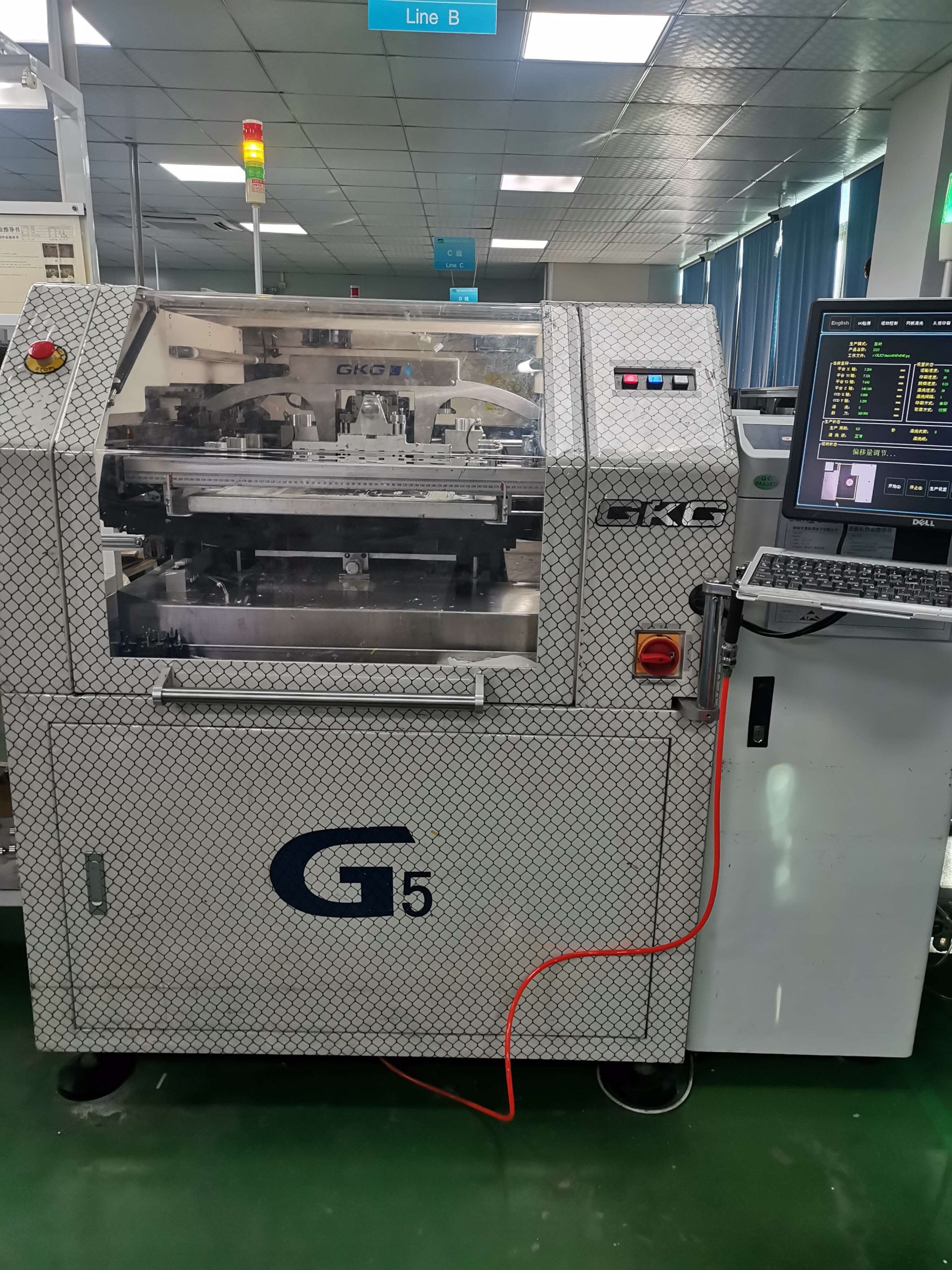
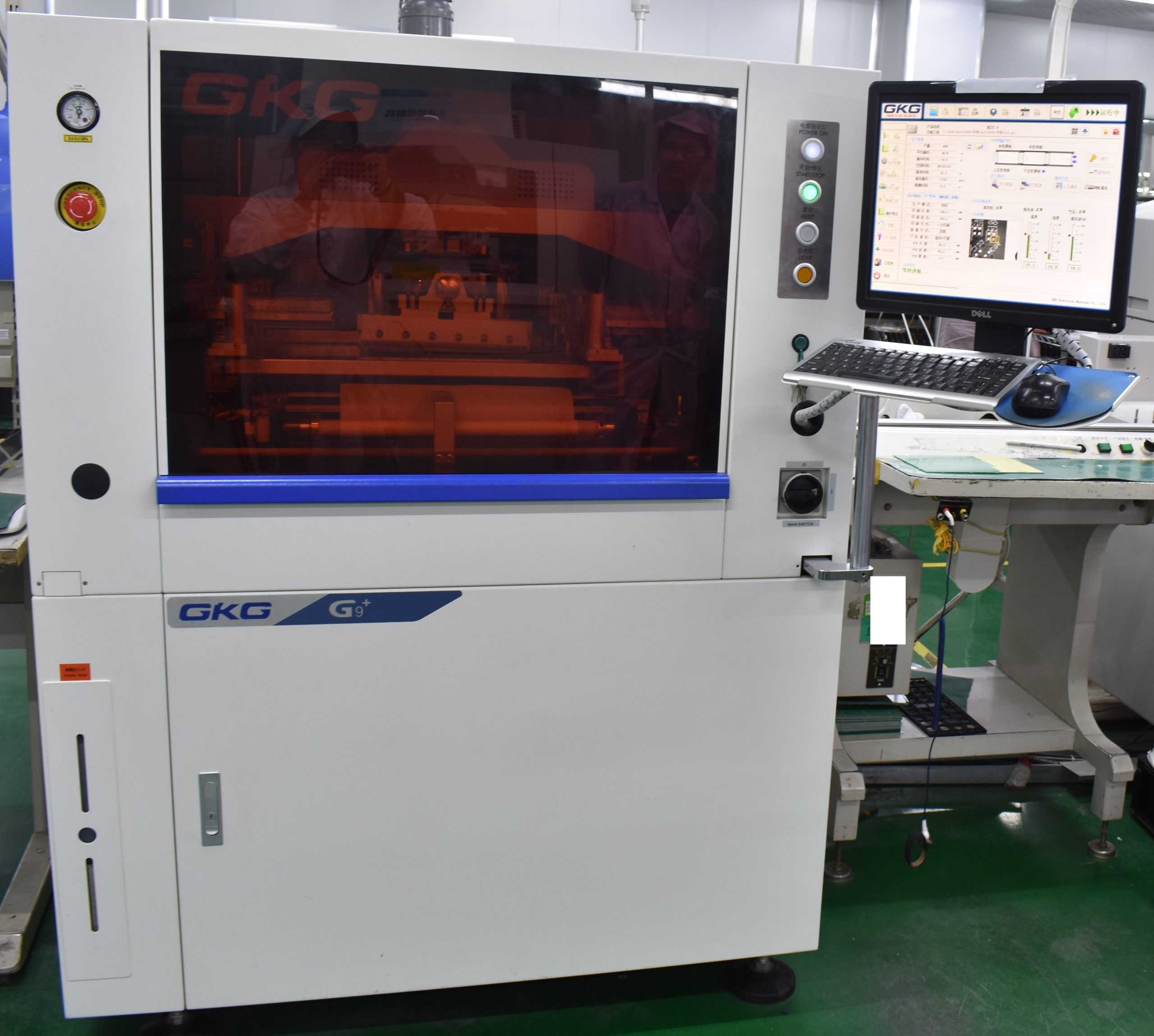
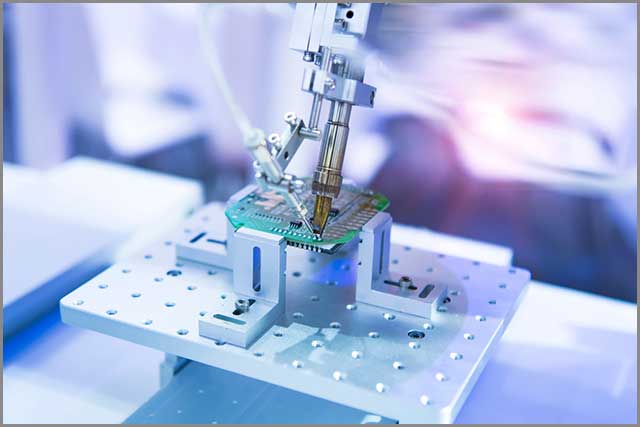
A solder paste printer applies paste to PCB pads using a metal stencil. The stencil aligns precisely with solder pad locations, ensuring accurate paste application.
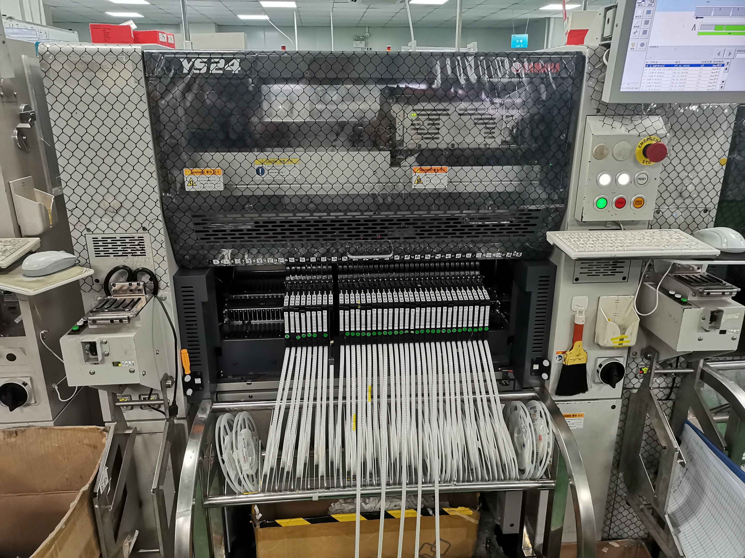
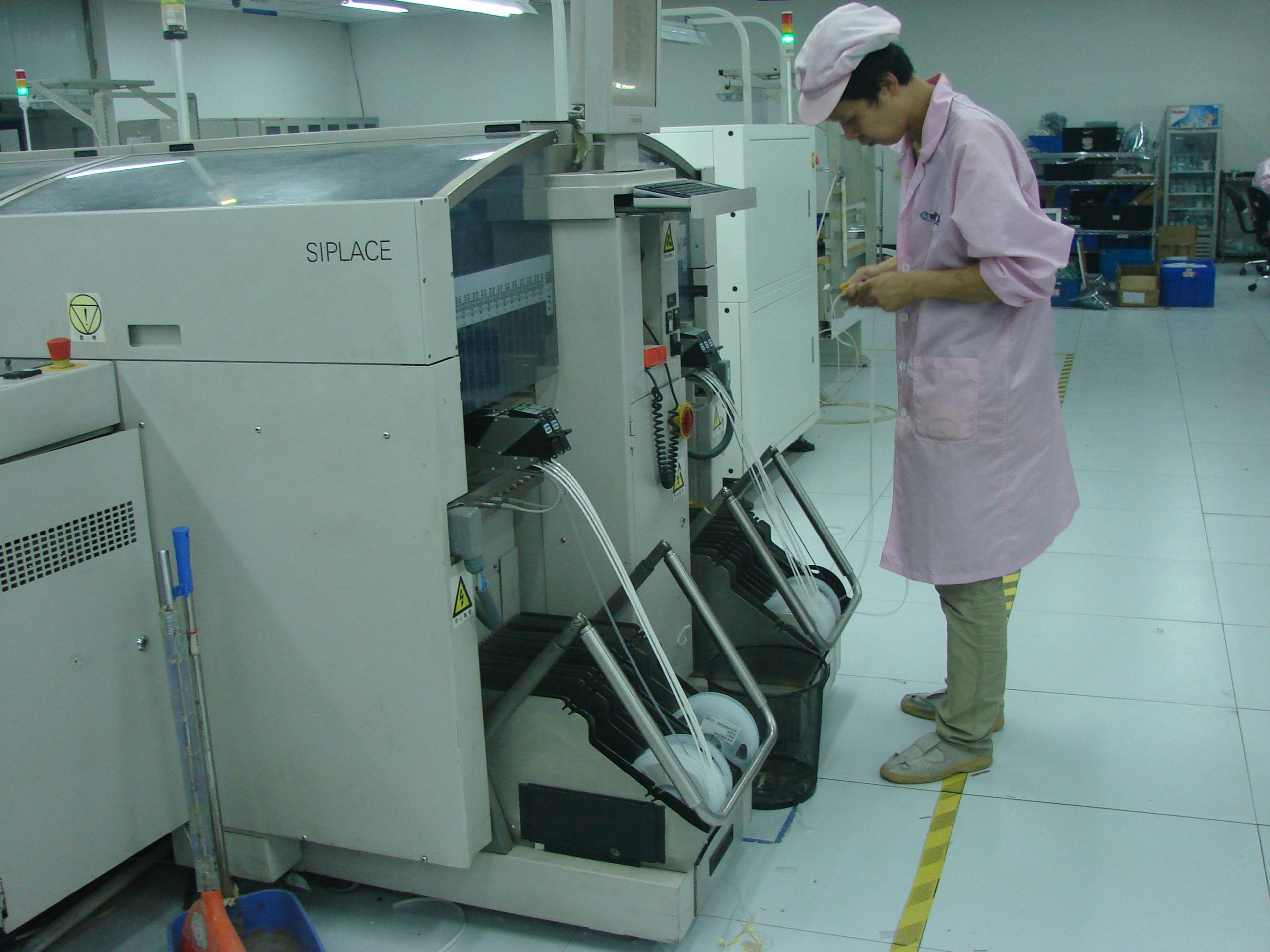
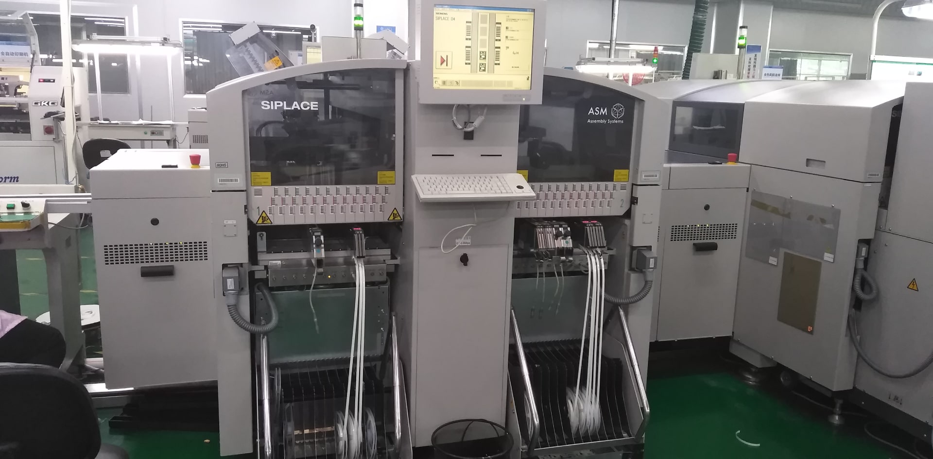
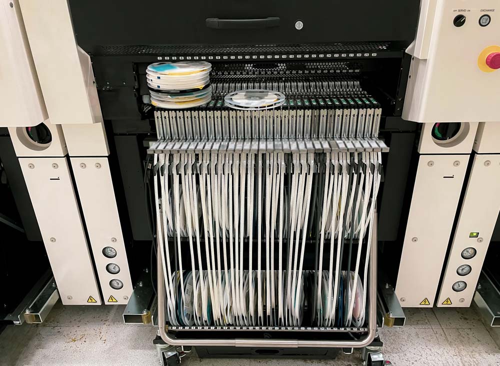
A pick-and-place machine precisely places SMT components onto the solder paste-covered pads using X-Y coordinates from the PCB layout. This process is crucial for using ICT to ensure PCB quality, detecting any placement errors early in the production cycle.
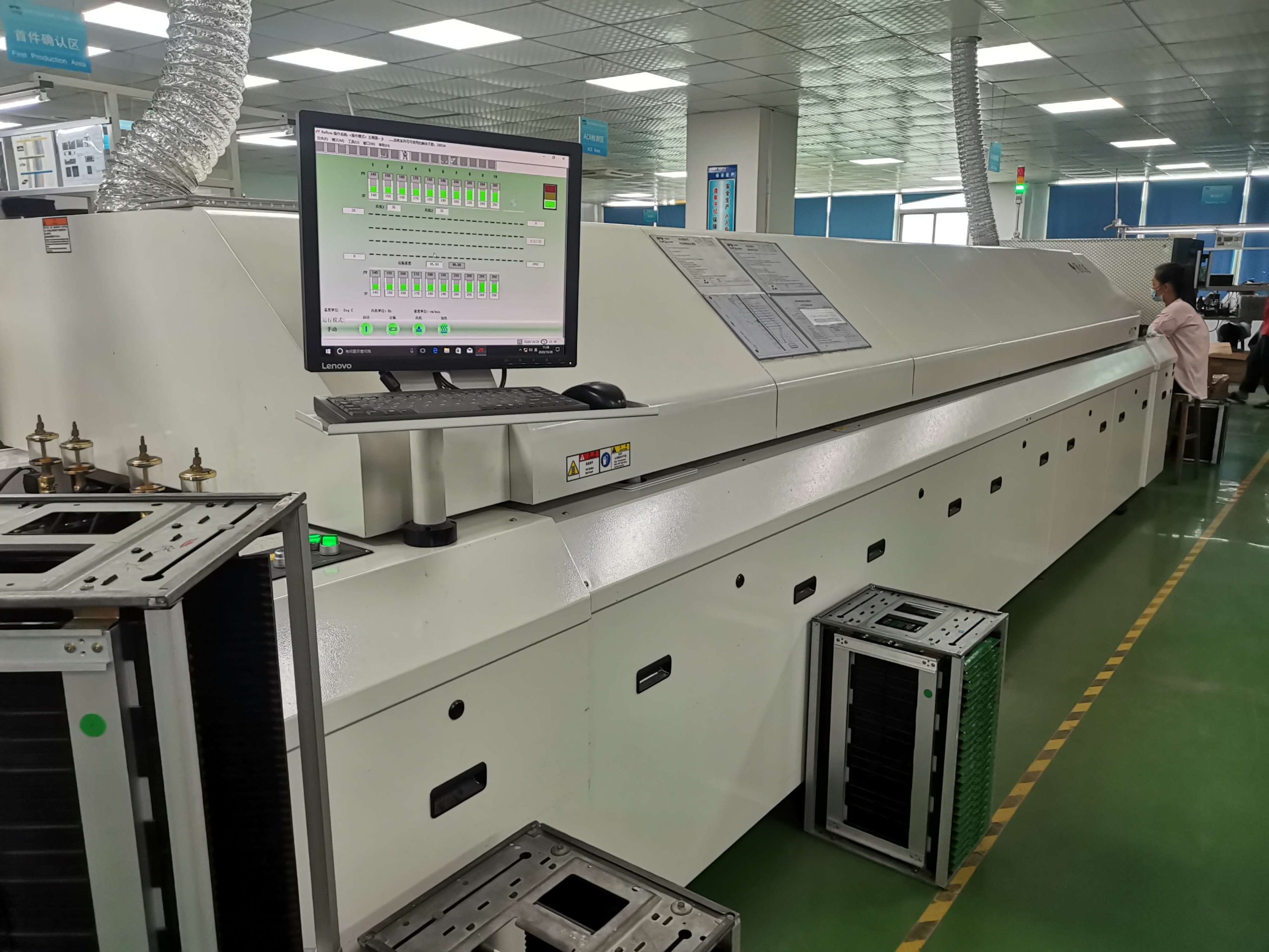
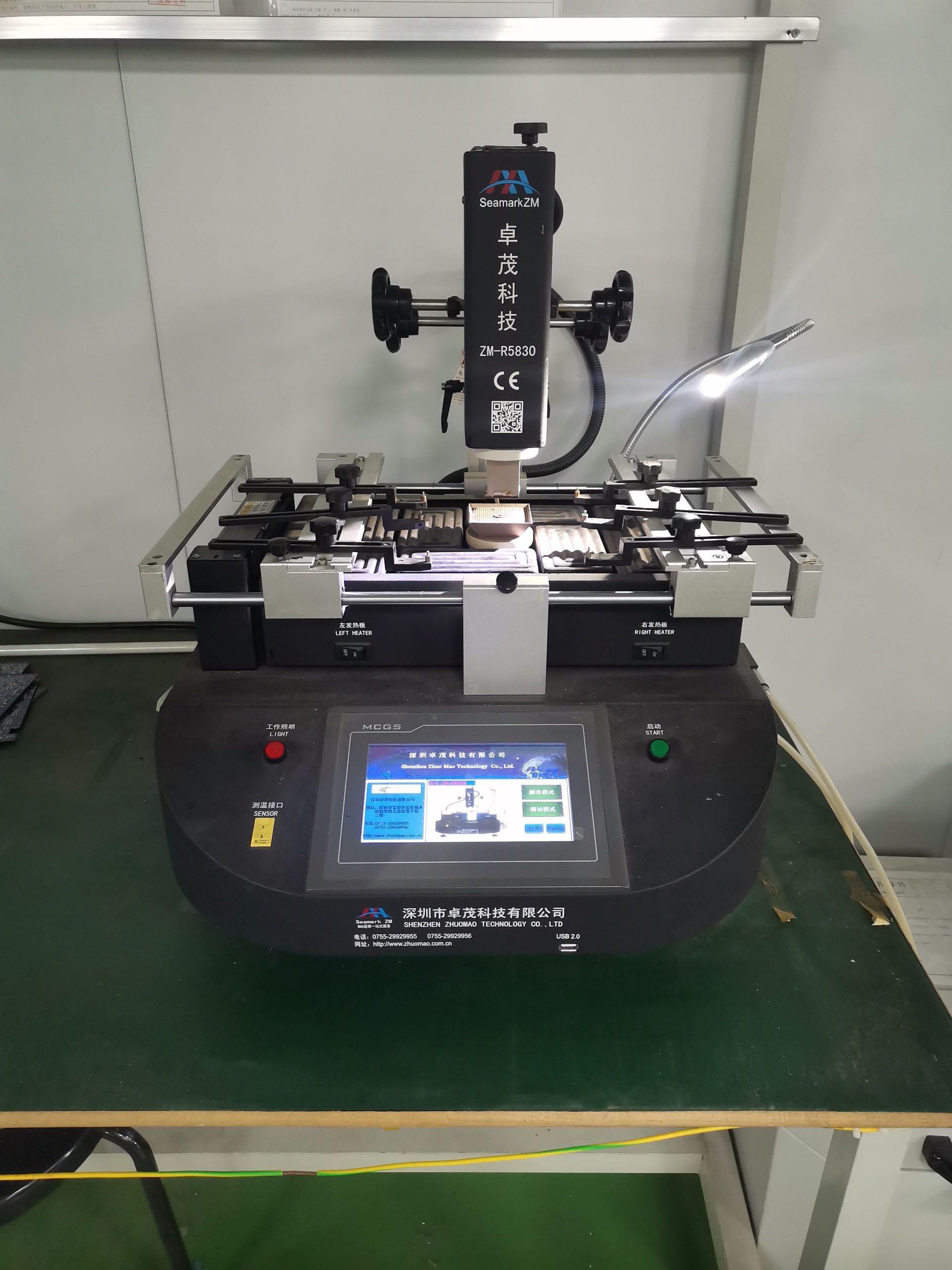
The board passes through a reflow oven to melt the solder and secure the components. This step is vital for the long-term reliability of the board, particularly in high density interconnect PCBs that have numerous components.
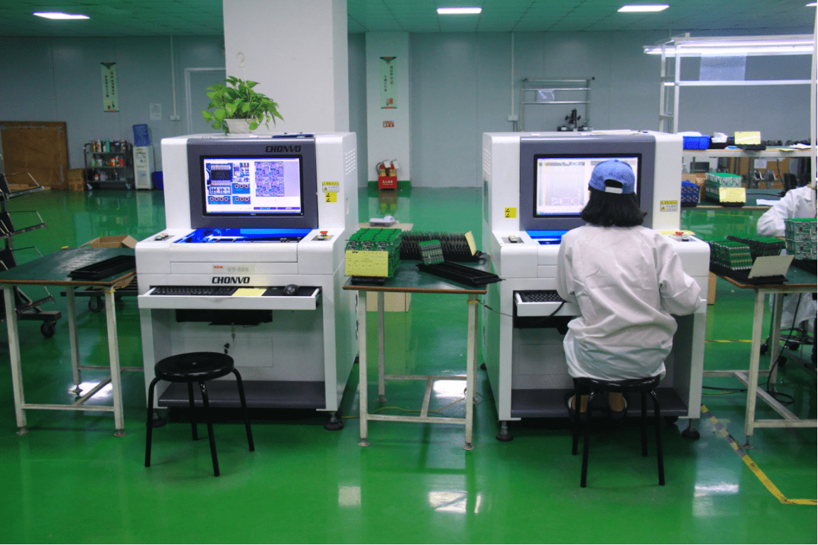
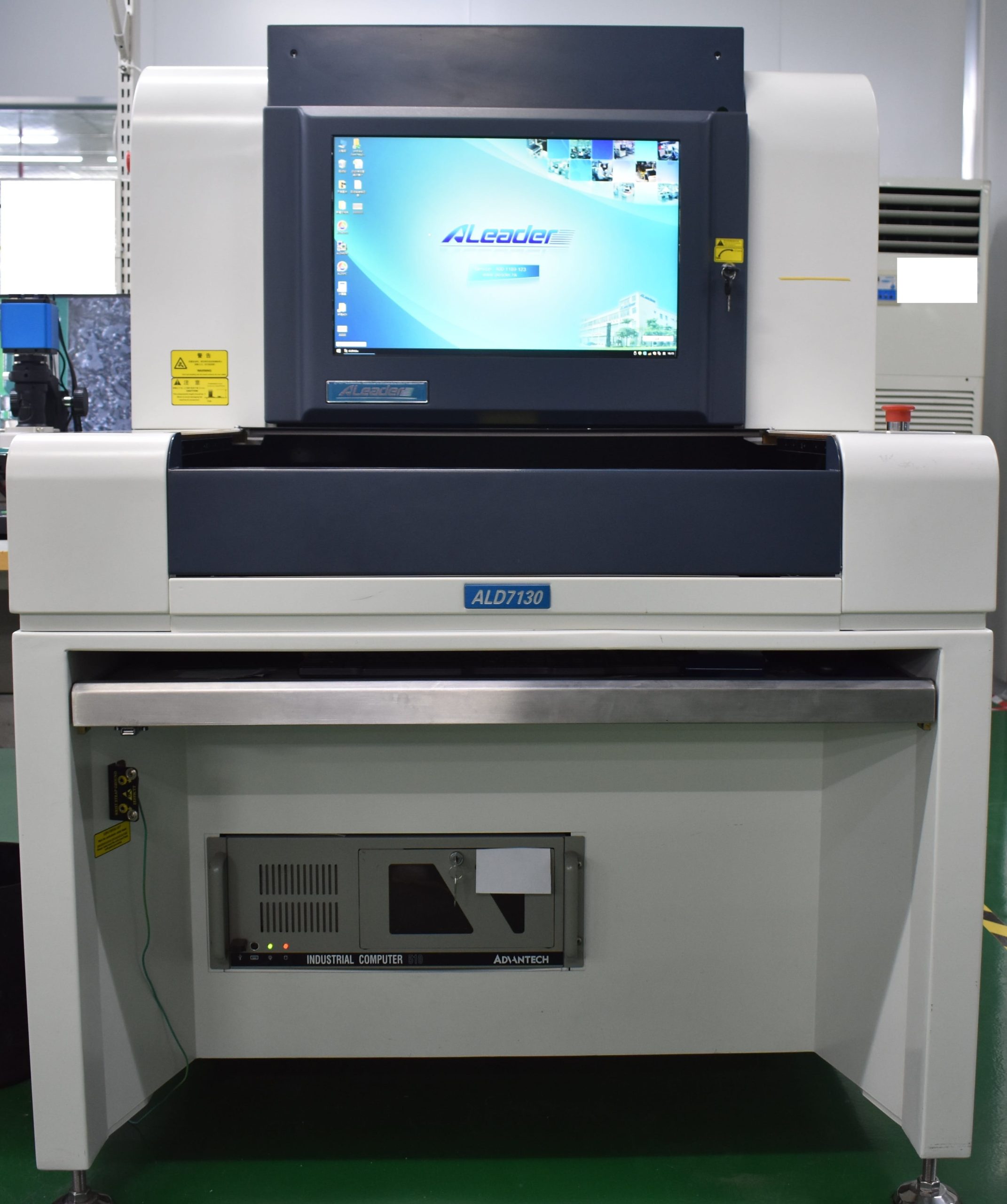
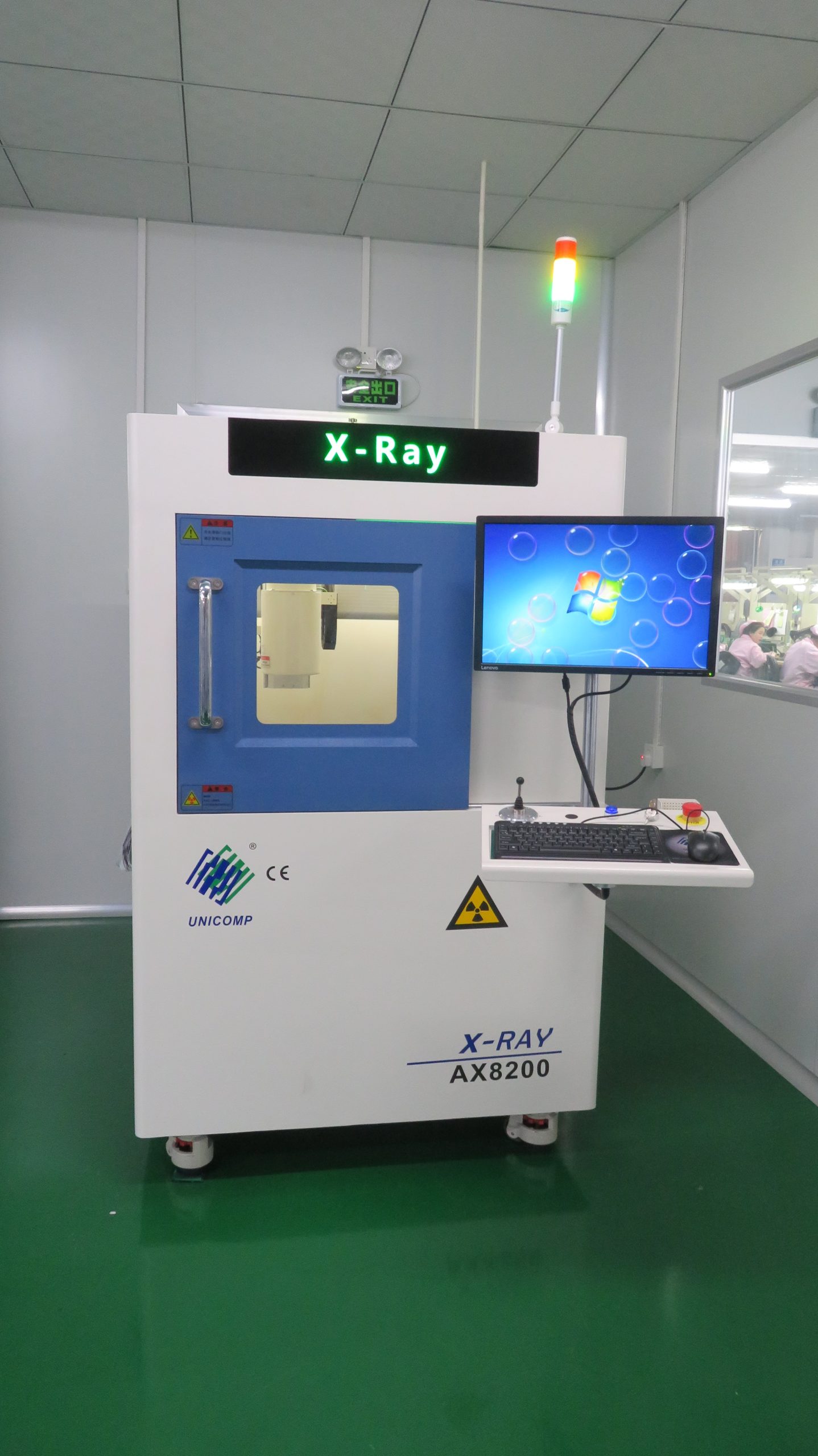
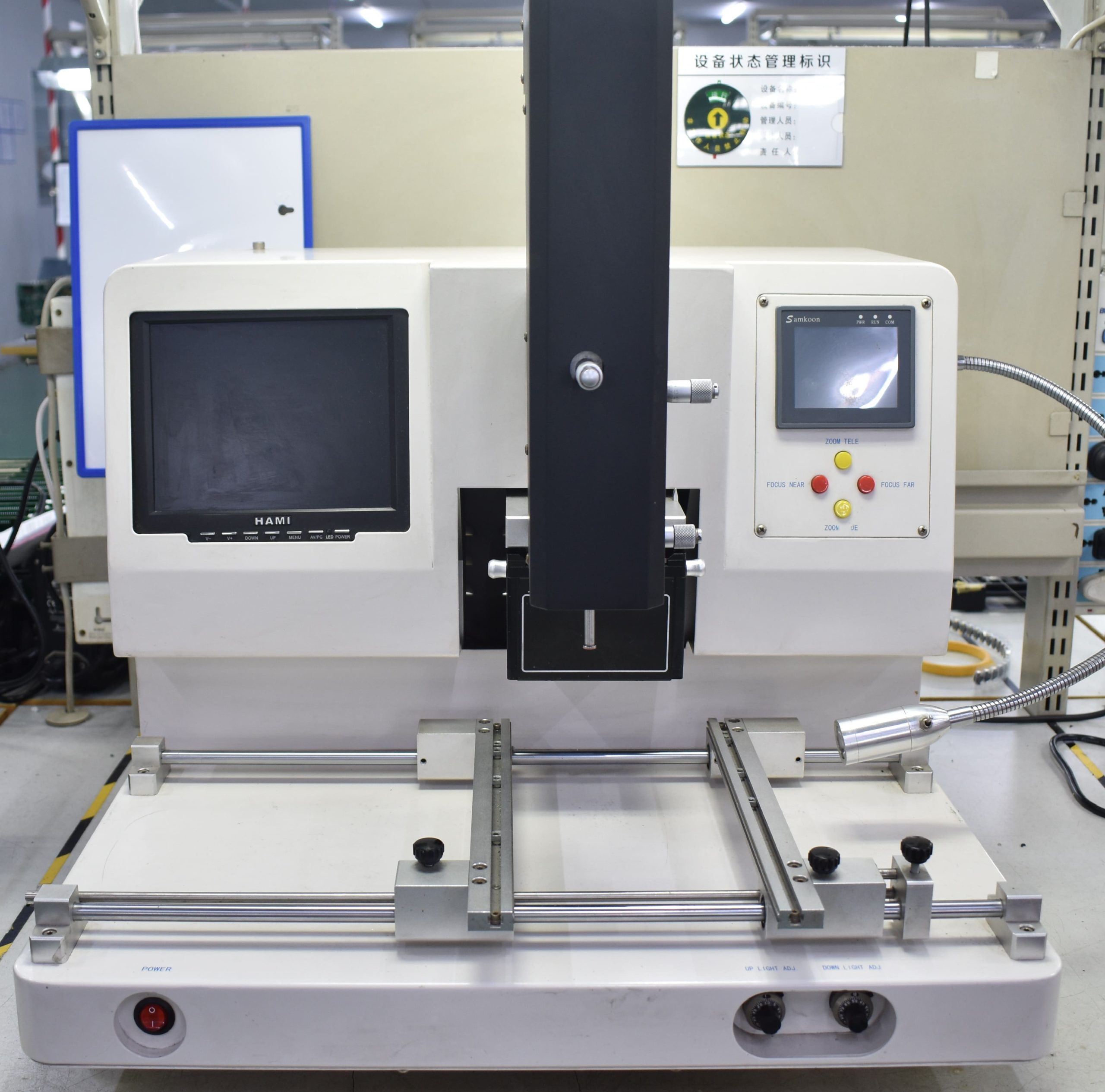
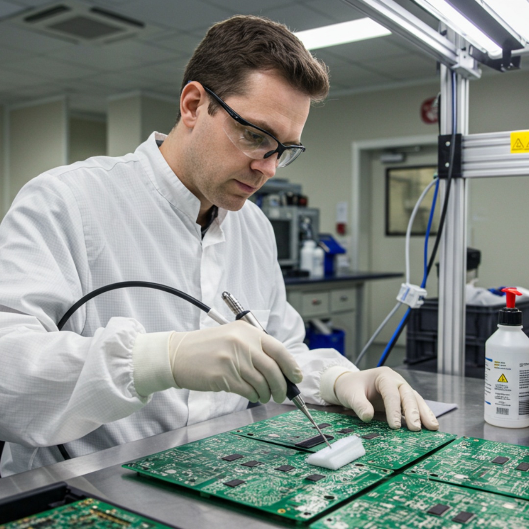
Methods like AOI, X-ray, and visual inspection detect defects. Faulty boards undergo rework and reinspection.
Functional tests such as flying probe, bed of nails, and solderability testing ensure the PCB assembly meets performance requirements.
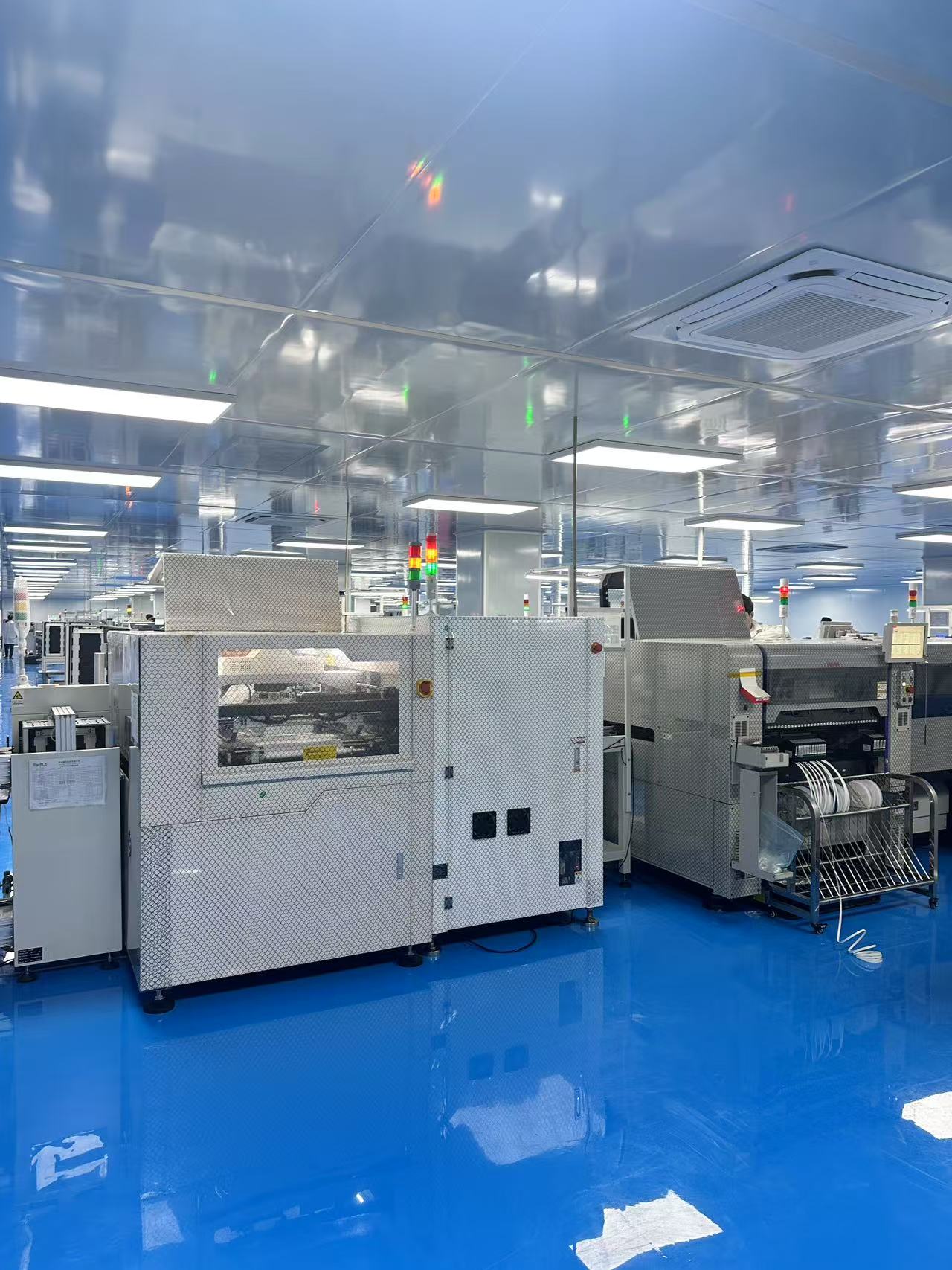
As a leading SMT PCB assembly manufacturer, we have nearly 20 years of experience providing high-quality PCB assembly prototyping and manufacturing. Our small-batch SMT assembly services allow you to test and validate your design before full-scale production—ensuring performance and reliability without high costs.
With over 3,000 satisfied clients, we support you from prototype to mass production, offering cost-effective solutions and fast turnaround times to help you bring your product to market efficiently. Whether you need quick-turn prototypes or high-volume SMT assembly, we deliver precision, quality, and expertise at every step.
Whether you’re in the consumer electronics industry or dealing with high-density interconnect PCBs, our team can assist you in understanding schematic diagrams and transforming them into fully functional prototypes and mass-produced boards.
| Quantity: 5 | 50 cm² | 100 cm² | 200 cm² | 400 cm² | 600 cm² |
|---|---|---|---|---|---|
| 1-Layer | $17 | $21 | $26 | $36 | $46 |
| 10-Layer | $259 | $279 | $308 | $359 | $412 |
Your final cost will depend on how many PCB you need. Request a free online pcb quote for your project now. New customers get $100 off their first project with us!
| Number of Layers | Number of Days |
|---|---|
| 1-12 layers | within 72 hours |
| 12+ layers | within 120 hours |
Lead time may extend depending on the quantity of PCB orders. Contact us today for a free quote to get an accurate estimation of the lead time you can expect.
From injection molding to complete assembly, OurPCB offers a full range of circuit board assembly online services. Our injection molding service helps create precise, durable enclosures, enhancing the protection and functionality of your designs. Whether you’re developing prototypes or scaling up for production, we deliver reliable, high-quality solutions to meet your needs.
We handle everything from parts sourcing to final assembly, providing a hassle-free experience that ensures top-quality boards every time.
Whether you need a few prototypes or large-volume batches, our flexible assembly services adapt to your project’s scope and timeline.
Stay environmentally responsible with our compliant assembly processes, offering RoHS and lead-free options for safe, reliable builds.
No matter the complexity, we can assemble boards of all configurations—single-layer, multi-layer, or a mix—to match your exact specifications.
From one-off prototypes to bulk orders, we accommodate projects of all sizes without compromising on quality or turnaround time.
Join our growing community of satisfied clients who rely on our dependable assembly expertise and dedicated customer support.
Mon-Fri: 24 hours,
Sat: 9am-6pm, GMT+8
Reach us at
[email protected]
24 hours online
+86-199-30589219
Mon-Fri: 24 hours,
Sat: 9am-6pm, GMT+8
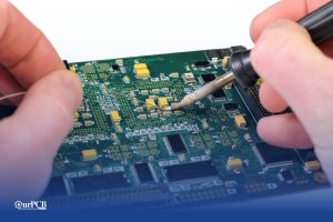
SMT (Surface Mount Technology) is a PCB production or assembly method that involves placing and soldering electronic components directly onto the PCB surface. The process requires a solder paste printer to apply the solder paste, a pick-and-place SMT machine for component placement, and a reflow oven to melt the solder and weld components to pads. If you’re working with these components, understanding how to operate an oscilloscope is crucial for proper signal validation during testing.
SMT is challenging for prototyping because steps like solder paste printing and component placement need stencils and pick-and-place files for specific board designs. Consequently, prototyping can be costly, but it is doable.
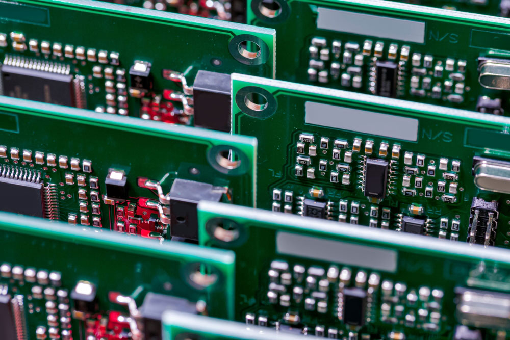
An SMD is a Surface Mount Device. An SMD device is mounted on a PCB utilizing surface mount technologies. SMD electronics are designed to not have components with leads that go through holes, as they are soldered onto pads on the surface. SMD parts include resistors, capacitors, and an SMD chip.
SMT is the surface mounting process in this PCB assembly technology, while SMD refers to the component or type of device used.
So, which one technology do you choose for your PCB? Here’s how SMT compares to THT:
SMT components are significantly smaller than THT parts, primarily because they have smaller/shorter leads or contact pads. THT devices have larger and longer leads.
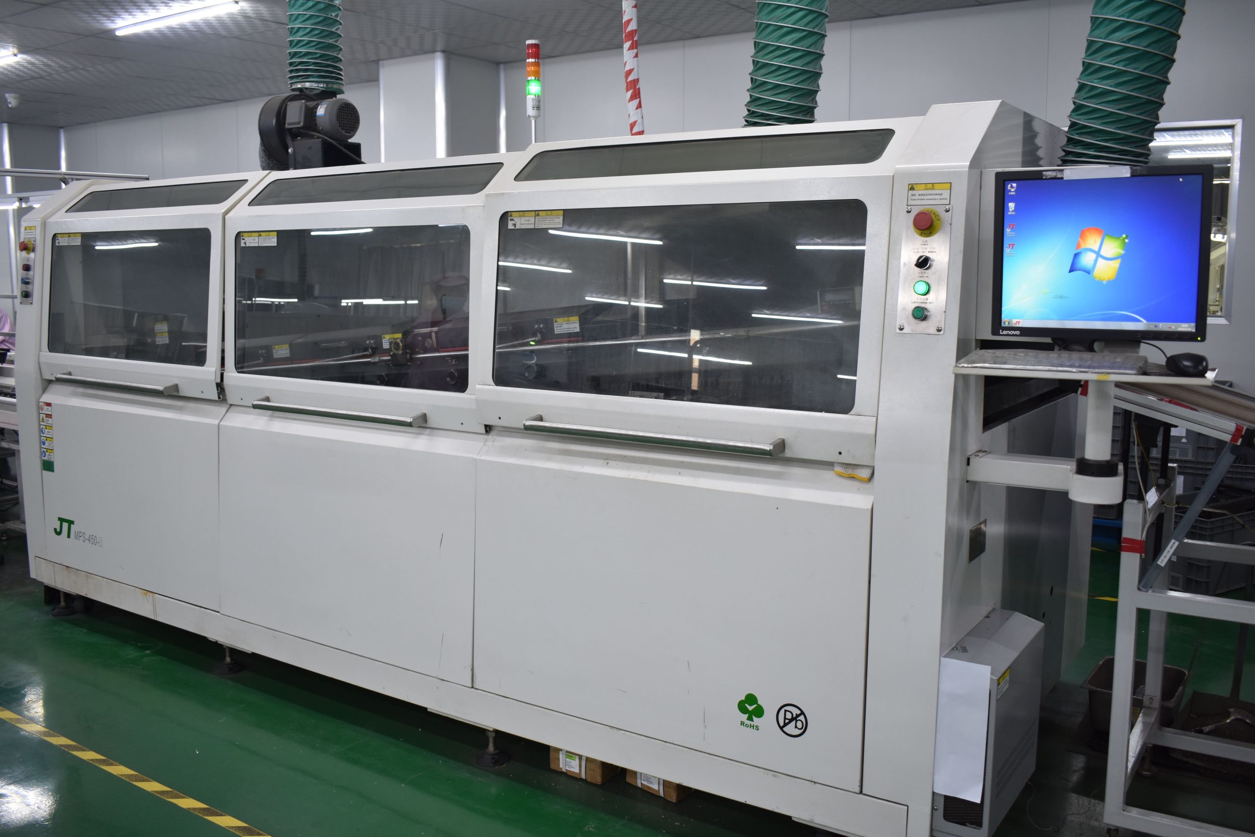
Assembling SMT components requires solder paste printing, component placement using a pick-and-place machine, and reflow soldering. But THT assembly needs component insertion machines followed by wave soldering.
THT provides more robust mechanical bonds with the board because the component pins go through the PCB and are soldered on the other side. These solder joints handle environmental and mechanical stresses better than SMT joints.
Both THT and SMT are technologies used to mount and solder components on a bare board. Here is how SMT is different from the traditional THT:
SMT components are significantly smaller than their THT counterparts, so it is possible to pack them at a higher density per unit area on the board’s surface.
Because they are smaller than THT components, SMT parts occupy less space on the board. This makes it possible to build smaller PCBs or leave more space for other functions.
THT creates electrical connections between the board and components by mounting component leads into holes drilled through the PCB. These leads are soldered on the other side of the plated-through hole to create a reliable mechanical and electrical joint.
However, SMT involves mounting components directly on the PCB surface, which requires no drilling.
SMT is important in electronics manufacturing because it:
These components are cheaper than their THT counterparts, and the assembly process is easier to automate.
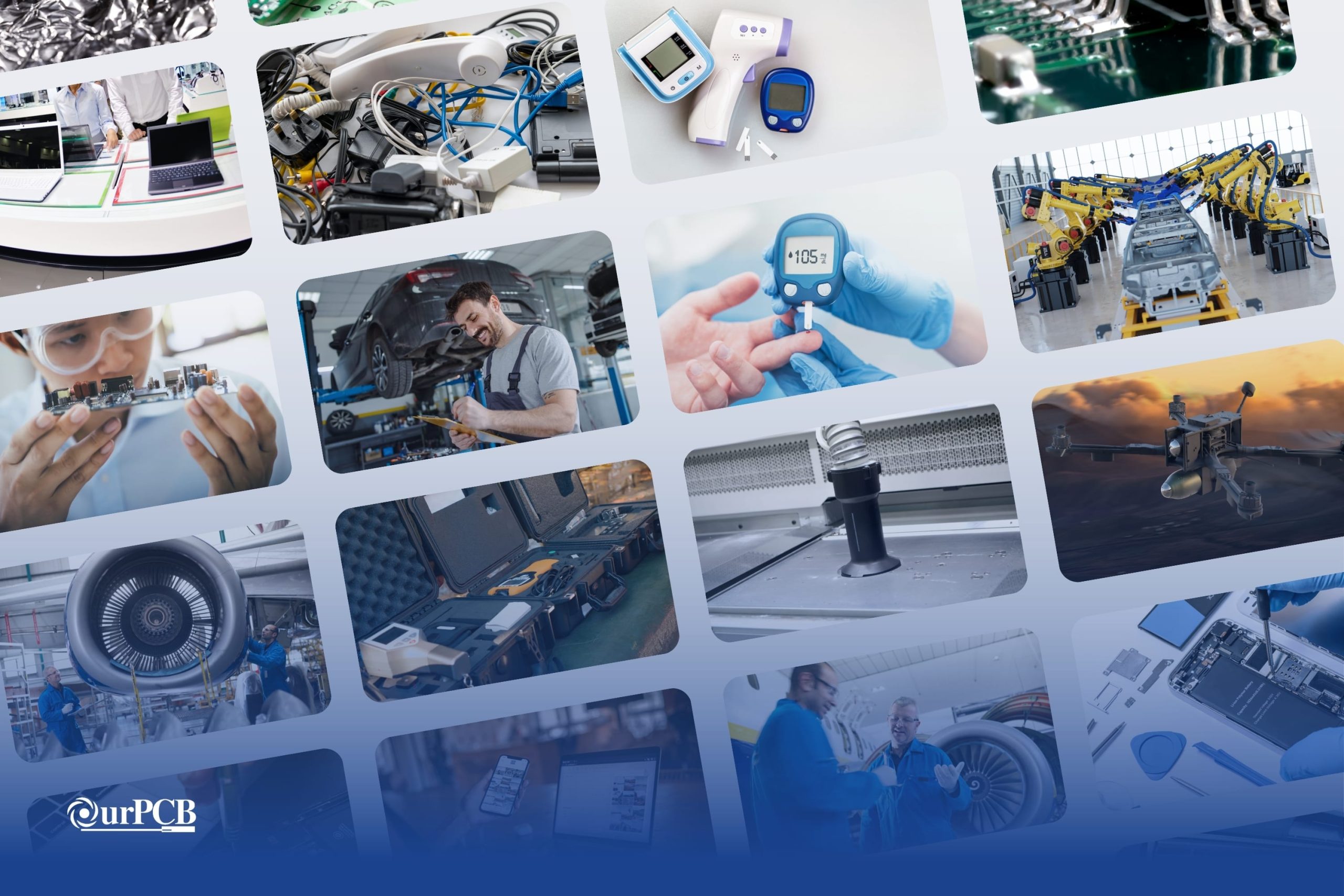
SMT is common in smartphones, laptops, smartwatches, and other compact consumer electronics because of its miniaturization advantage.
Compact medical equipment like heart rate monitors, EMG, EEG, and ECG sensors, glucometers, and pacemakers require miniaturization, which is one of the benefits of SMT. The reliability offered by SMT is also important in medical devices.
Modern vehicles have several control systems and modules that require efficient, stable, and reliable operations. SMT provides these advantages.
SMT components can weigh up to 10 times less than THT devices, which results in high PCB weight reduction. This factor is important in aerospace and defense applications because lift pulls in the opposite direction of weight. Drones, planes, and rockets benefit immensely from this technology.
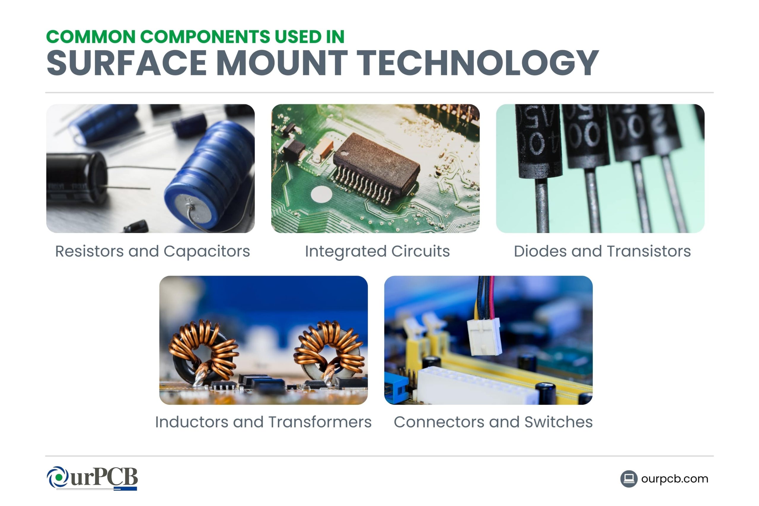
Resistors are the most common SMD components, and their purpose is to limit the flow of electric current through the circuit. They include various types, such as thin film, thick film, wire-wound, and current-sense resistors.
On the other hand, capacitors store electric charge, functioning as temporary batteries or power supplies in the circuit. They include ceramic, electrolytic, film, and tantalum capacitors.
ICs are complex SMT components that have multiple transistors, resistors, diodes, capacitors, etc., on a single chip. They include digital, analog, mixed-signal, and power management ICs.
Diodes are 2-terminal semiconductors that only allow current to flow in one direction to help in rectification, signal processing, lighting, and voltage regulation. On the other hand, transistors are 3-terminal semiconductors that switch or amplify electric signals.
Inductors are single coils that store energy in a magnetic field when current flows through them. They are common in power supplies and analog circuits, where they stabilize the current flow and filter out high-frequency noise.
Transformers have at least two coils. They transfer energy from one circuit to another using magnetic induction.
SMD connectors provide electrical connections between the PCB and external devices without permanent attachment (soldering). On the other hand, switches give manual control over the electrical current flow in a circuit.
Finding the right wiring harness manufacturer for your vintage ride can be a real headache. Those beautiful old machines need special wiring that looks period-correct
Would your car be able to run without wire harnesses? Not a chance. Wire harnesses connect all the electrical parts together. No harness means no
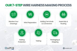
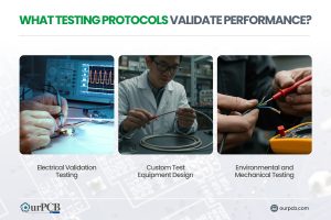
Making wire harnesses isn’t complicated. At OurPCB, we create custom wire harnesses for an expansive range of industries every day. While it’s a complicated process,
Prototype cable assemblies are the very important place in between PCB design ideas and interconnects. OurPCB brings prototype assemblies with PCB solutions to your tables.
PCB thermal management prevents component overheating through strategic heat transfer techniques. Without proper thermal control, electronics are at risk of electronic failures through weakened solder
ContentsKey TakeawaysWhat is a Multilayer-Printed Circuit Board?How do Multilayer PCB Boards Work?Multilayer PCB ApplicationsMultilayer PCB Manufacturing Process: StepsMultilayer PCB Manufacturing MachinesBenefits of Multilayer Circuit BoardsWhat
We use cookies to improve your browsing experience, which may include personal information. By clicking "Agree," you accept our Privacy Policy and cookie use. You can change your cookie settings in your browser anytime.
Agree
 Chat With Us
 Free Quote