Metal Core PCB Manufacturer USA
- Professional engineer review; strict quality control for each process.
- Advanced Testing Technology To Ensure the Quality such as AOI Test, E-Test, X-RAY, Impedance Control.
- We committed to helping customers get the highest quality products and services with competitive prices (especially multilayers PCBs).
- 1Order and Procurement
- 2PCB Manufacturing and Preparation
- 3Assembly and Soldering
- 4Inspection and Quality Control
- 5Finalization and Shipping
- Bare PCB in 8 working hours
- PCBA with components in 2 working days
- Bare PCB manufacturing
- Components sourcing
- PCB assembling
- Wire harness manufacturing
- Casing /Housing manufacturing
- Programming/Testing
Adrian Leitch
Andrew Durrant
Andrew Peeler
Andrew Wood
Ben Thomas
Darren Larosa
Debra Beukes
Eastern Europe Archives
frankyc
Fred Van
Greg MacDonald
John Powell
Jonathan Pippard
Jordan Thurgood
Justin Regan
Mark A
Mark Pagura
Maryanne Hassell
Matthew O'Neill
mitch clark
Oli
Peter Lambert
Sasha Marks
Slavko Mali
SPI MX
Steve Visser
Steven Munari
Steven Vatev
Tane Pendragon
Tasmiah Khan
Trevor Gardner
Free Consultation
Contents
- Metal Core PCB Manufacturer USA
- Get Free quote now
- Need Metal Core PCB?
- What are MCPCBs?
- Composition and Structure of MCPCBs
- Metal Core
- Dielectric Layer
- Copper Circuit Layer
- Types of Metal Core PCBs
- Single-Layer Metal Core PCBs
- Multilayer Metal Core PCBs
- Aluminum Core MCPCBs
- Copper Core MCPCBs
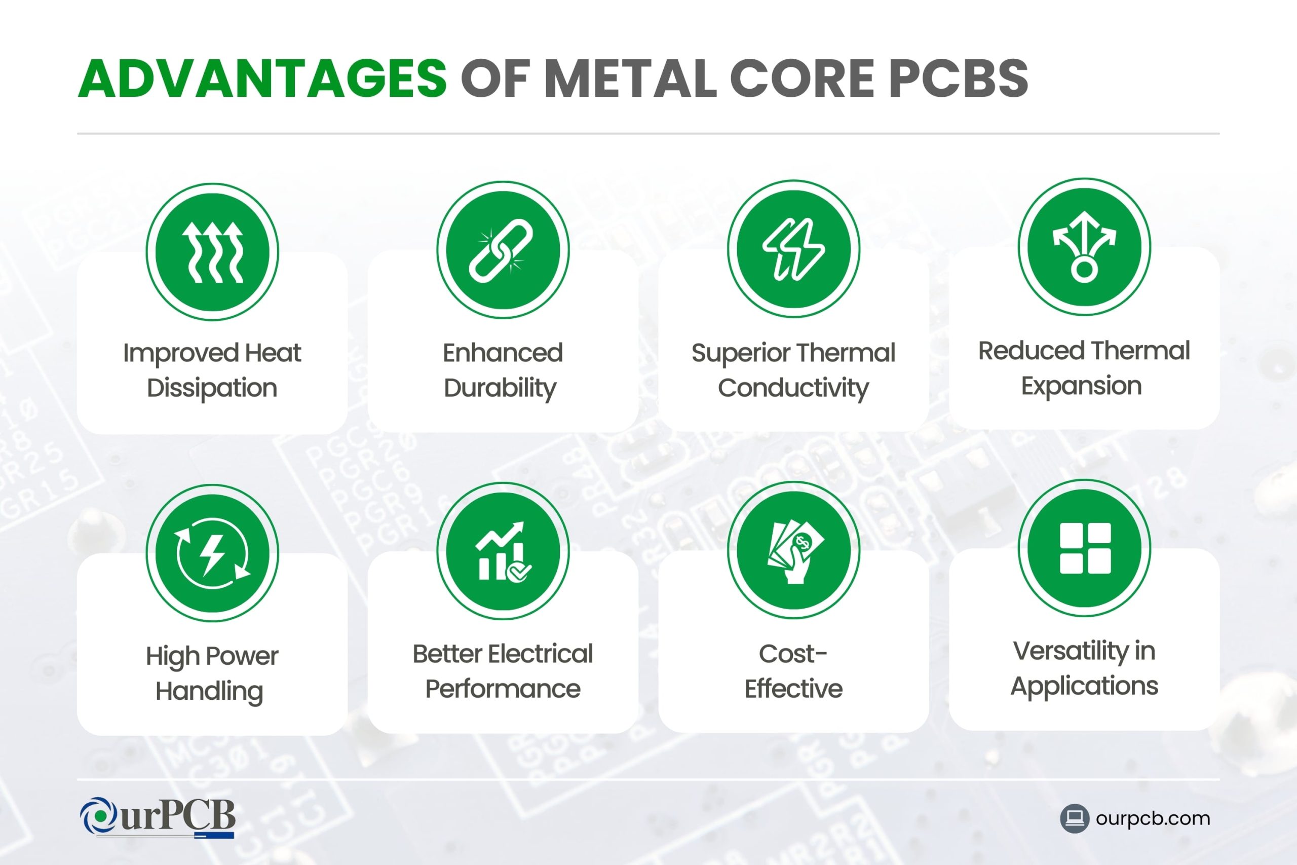
- Advantages of Metal Core PCBs
- 1. Improved Heat Dissipation
- 2. Enhanced Durability
- 3. Superior Thermal Conductivity
- 4. Reduced Thermal Expansion
- 5. High Power Handling
- 6. Better Electrical Performance
- 7. Cost-Effective for High-Power Applications
- 8. Versatility in Applications
- MCPCBs: Manufacturing Process
- Single-Layer Process
- Multilayer Process
- Design Considerations for MCPCBs
- Thermal Management
- Layer Stack-Up and Material Selection
- Electrical Performance
- Component Placement and Mounting
- Mechanical Stability and Durability
- Cost and Manufacturability
- Environmental Considerations
- Standards and Regulations
- Comparison: MCPCBs vs. Traditional FR-4 PCBs
- Challenges and Solutions in MCPCBs Manufacturing
- Metal Core PCB Fabrication Challenges
- Solutions and Workarounds
- Cost Factors in MCPCB Production
- Material Costs
- Manufacturing Complexity
- Production Volume Considerations
- Long-Term Benefits and ROI
- Take a Factory Tour!
- More PCB Services
Need Metal Core PCB?
We at OurPCB are here to assist you with all your Metal Core PCB needs. We offer various types of metal core PCBs to meet your needs, including single-sided, double-sided, and multilayer metal core PCBs. These PCBs efficiently manage heat, enhancing performance and reliability.
As a leading printed circuit board manufacturer, with numerous happy customers worldwide, especially in the USA, we provide high-quality, reliable PCB assembly services for all your electronic requirements.
A metal core PCB might not be the go-to for most projects, but it has some advantages, especially when it comes to heat dissipation. If you’re working on a project that needs stringent temperature regulation, a metal core PCB might be just right.
OurPCB is an MCPCB manufacturer dedicated to meeting all your PCB needs. From FR-4s to MCPCBs, we have what you need to make your project a success! Our experts have compiled this article to give you all the information you need on MCPCBs, their uses, and their limitations.
What are MCPCBs?
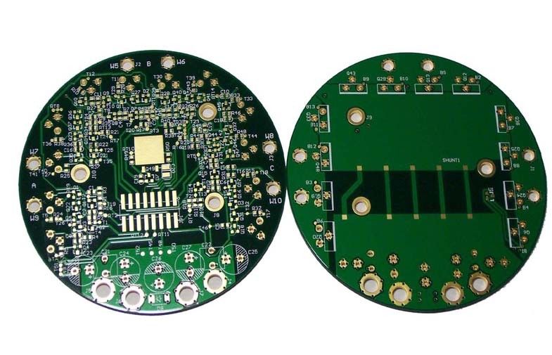
Metal Core PCBs (MCPCBs) are a type of printed circuit board that use a metal base material as the heat spreader portion of the board. The metal base is typically aluminum, but it can also be copper or a mixture of special alloys. This helps to dissipate heat away from the components, making metal core printed circuit boards ideal for high-power and high-heat applications.
Composition and Structure of MCPCBs
Metal Core
The primary function of the metal core is to act as a heat sink, drawing heat away from components and dissipating it. This helps maintain optimal operating temperatures, which can make or break high-power systems.
Dielectric Layer
The dielectric layer in MCPCBs is usually made from a thermally conductive but electrically insulating material. Epoxy resin infused with ceramic fillers is a common choice.
This layer separates the metal core from the copper circuit layer and transfers heat from the circuit layer to the metal core while preventing electrical conduction between the two.
One of the most important properties of the dielectric layer is its thermal conductivity. Higher thermal conductivity means better heat transfer from the heat-generating components to the metal core.
Copper Circuit Layer
The copper circuit layer is where the actual electrical circuits are formed. This layer is etched to create the necessary pathways for electrical current to flow between components. The thickness of the copper layer can vary depending on the current-carrying requirements of the PCB. For high-power applications, you would often use a thicker copper layer.
Types of Metal Core PCBs
Single-Layer Metal Core PCBs
Single-layer metal core PCBs are the most basic type. They consist of a single conductive layer of metal, usually aluminum or copper, which acts as the heat spreader. This design is ideal for simple electronic applications where effective heat dissipation is important.
Single-layer MCPCBs are commonly used in LED lighting, power supplies, and automotive lighting. Their straightforward construction allows for efficient manufacturing and cost-effectiveness.
Multilayer Metal Core PCBs
Multilayer MCPCBs feature multiple layers of conductive material separated by insulating layers. These PCBs are designed for high-performance applications that need enhanced thermal management and higher component density. They offer better electrical performance and more design flexibility than single-layer PCBs. This renders them suitable for more sophisticated and demanding applications.
Aluminum Core MCPCBs
Aluminum core MCPCBs are widely used due to their excellent thermal conductivity and affordability. The aluminum core helps to dissipate heat away from components quickly, maintaining performance, mechanical strength, and longevity.
Copper Core MCPCBs
Copper core MCPCBs are ideal for high-power applications where high temperatures could compromise the PCB. Although more expensive than aluminum cores, copper cores provide better thermal performance and electrical conductivity.
Advantages of Metal Core PCBs
1. Improved Heat Dissipation
Metal core boards substrate notably improves heat dissipation. In fact, it can transfer heat 8to 9 faster than FR-4 PCBs! This helps maintain optimal operating temperatures for electronic components, prevents overheating, and extends the lifespan of the device.
2. Enhanced Durability
The metal core provides a sturdy base, making these PCBs more durable and resistant to mechanical stress and damage. They can also withstand harder physical impacts, as they’re 2 to 4 times stiffer than polyamide or FR4 designs.
3. Superior Thermal Conductivity
Compared to traditional fiberglass PCBs, metal core PCBs offer superior thermal conductivity. This allows for efficient heat transfer away from hot spots, boosting the overall performance and reliability of electronic circuits, especially in high-power applications.
4. Reduced Thermal Expansion
The metal substrate in these PCBs reduces thermal expansion, which minimizes the risk of component failure due to thermal stress. This stability is especially important in applications where temperature fluctuations are common.
5. High Power Handling
Metal PCBs are ideal for high-power applications due to their ability to handle higher currents without significant temperature increases. This makes them suitable for LED lighting, automotive, and power supply applications.
6. Better Electrical Performance
The improved heat management and stability provided by metal core PCBs result in better electrical performance. Components can operate at their optimal levels without the risk of overheating, maintaining consistent performance over time.
7. Cost-Effective for High-Power Applications
While the initial cost of metal core PCBs may be higher than traditional PCBs, their ability to manage heat and reduce component failure can lead to cost savings in the long run. They can eliminate the need for additional cooling components, reducing overall system costs.
8. Versatility in Applications
Metal Core PCBs are versatile and can be used in a wide range of applications, including automotive, aerospace, industrial, and LED lighting. Their robust thermal and mechanical properties make them suitable for various demanding environments.
MCPCBs: Manufacturing Process
Single-Layer Process
The manufacturing process for single-layer metal core PCBs (MCPCBs) is similar to standard FR-4 PCBs. Firstly, a metal base is chosen for its high thermal conductivity. This is then coated with a thin dielectric layer, which provides electrical insulation while also facilitating heat transfer.
The dielectric is usually a ceramic-filled polymer or other thermally conductive materials. Next, a layer of copper foil is laminated onto the dielectric layer. This copper layer is then etched to create the necessary circuit patterns. Finally, a solder mask is applied to protect the circuitry, and surface finishing processes are performed to prepare the PCB for component mounting.
Multilayer Process
The multilayer MCPCB manufacturing process is more complex. Initially, a metal core is drilled with slightly larger holes, which are filled with an insulating gel to prevent short circuits. This gel is cured and plated with copper to form vias and the metal core is then layered with multiple dielectric and copper layers, pressed, and bonded together.
Each dielectric layer provides electrical insulation and thermal conductivity. The stack is aligned, and through-holes are drilled through the entire structure. These holes are then plated to establish electrical connections between layers.
Design Considerations for MCPCBs
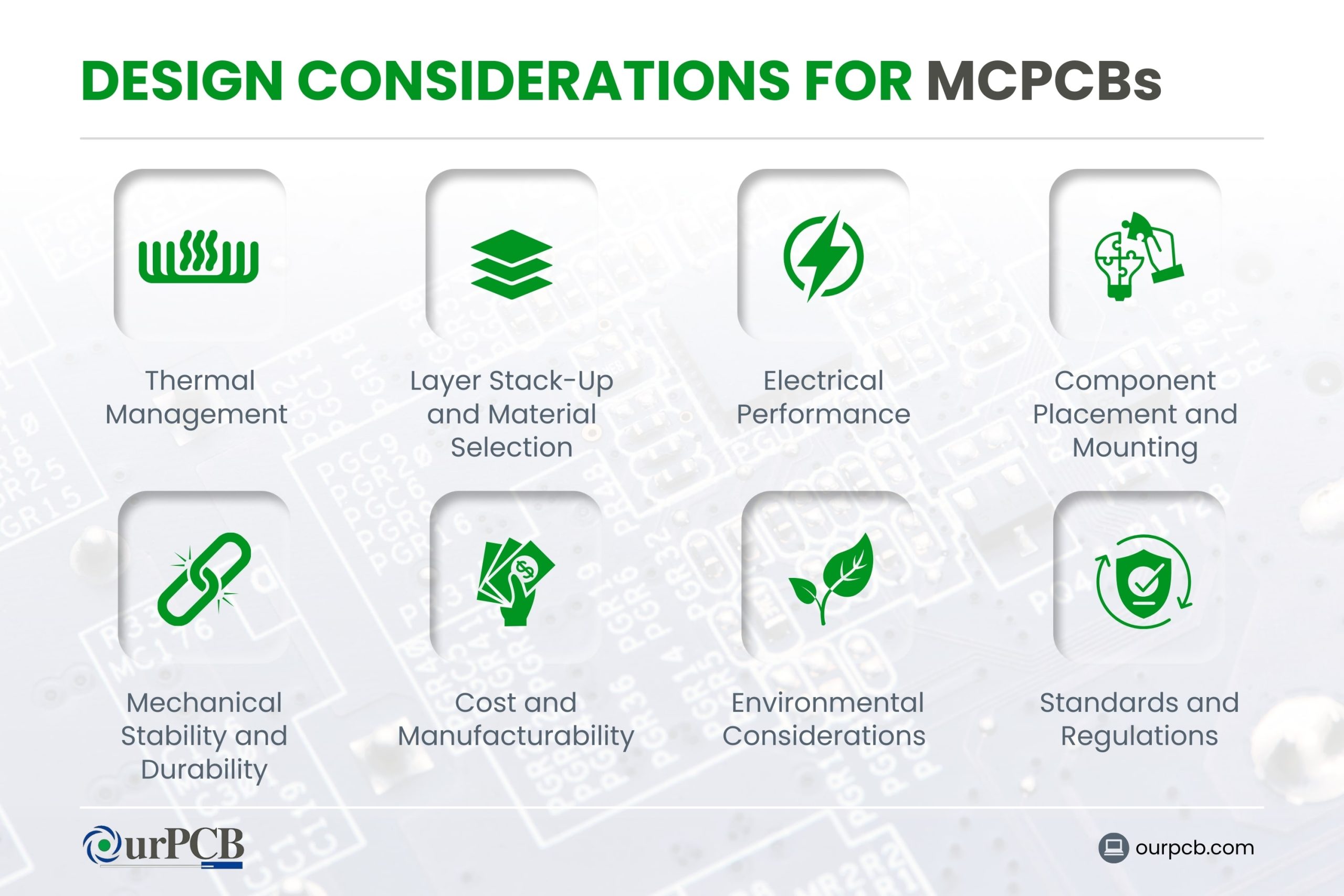
When designing metal core printed circuit boards, several key factors must be taken into account for optimal performance and thermal management. Here are some important PCB design considerations:
Thermal Management
The metal core conducts heat away from heat-generating components. Make sure that high-power components are placed near the metal core to maximize heat dissipation. Thermal vias can also be used to transfer heat from the top layers to the metal core efficiently.
Layer Stack-Up and Material Selection
MCPCBs usually consist of a metal core layer sandwiched between dielectric and copper layers. High thermal conductivity materials such as polyimide or ceramics are often preferred to enhance heat dissipation.
Electrical Performance
Maintaining signal integrity involves careful routing of high-speed signal traces and managing impedance control. The metal core can act as a large ground plane, reducing electromagnetic interference (EMI) and enhancing overall circuit performance.
Component Placement and Mounting
Use surface-mount components to keep the design compact and to optimize heat transfer. For double-sided MCPCBs, apply antipads (non-plated holes) to isolate vias from the metal core and prevent short circuits. Avoid plating through-holes in single-sided designs to reduce the risk of short circuits between layers.
Mechanical Stability and Durability
MCPCBs provide excellent mechanical support due to their rigid structure. This makes them suitable for applications subject to mechanical stress and vibration. Make sure that the design accommodates the mechanical properties of the metal core to avoid issues during manufacturing and in the final application.
Cost and Manufacturability
MCPCBs are generally more expensive than standard PCBs due to the cost of materials and the complexity of the manufacturing process. Design for manufacturability by considering the capabilities of the PCB manufacturer and aiming for simplicity where possible. Collaborating with manufacturers early in the design process can help.
Environmental Considerations
Consider the operating environment of the MCPCB. Factors like temperature range, humidity, and potential exposure to corrosive substances should influence material selection and protective coatings. Make sure the MCPCB is designed to withstand its intended environment.
Standards and Regulations
Adhere to industry standards and regulations specific to MCPCBs, such as IPC-6012D for rigid PCBs and thermal management guidelines. Compliance with these standards ensures quality, reliability, and safety in end-use applications.
Comparison: MCPCBs vs. Traditional FR-4 PCBs
The experienced team at OurPCB has summarized the key differences between MCPCBs and traditional FR-4 PCBs below:
Specification | Metal Core PCBs | Traditional FR-4 PCBs |
---|---|---|
Thermal Conductivity | Significantly higher thermal conductivity (1 to 4W/mK) | Lower thermal conductivity (around 0.3 W/mK) |
Thickness Variation | Limited thickness variations due to metal core and added rigidity | Wide range of thickness options and customizable layer combinations |
Heat Transfer | Excellent heat dissipation due to structure of metal core layer | Require additional (less efficient) heat management techniques like heat sinks and thermal vias |
Plated Through-Holes (PTH) | – Typically don’t use PTH due to short circuit risk – Rely on surface-mounted technology (SMT), which simplifies manufacturing process | – Use PTH for connecting layers and components – PTH can help in heat dissipation through vias |
Rigidity | – Enhanced rigidity due to metal core – More robust against mechanical stress and environmental factors (e.g., vibration and shock) | – Less rigid – May require additional support in demanding environments |
Cost | – Generally more expensive – Higher cost due to materials and manufacturing steps – Justified cost in applications requiring efficient thermal performance and reliability | – More cost-effective – Preferred for less demanding applications where thermal management is not a major concern |
Challenges and Solutions in MCPCBs Manufacturing
Metal Core PCB Fabrication Challenges
- Material Selection: Inadequate PCB materials can result in poor thermal conductivity, mechanical instability, or electrical performance issues.
- Layer Alignment: Precise alignment of the layers in MCPCBs is difficult due to the different coefficients of thermal expansion (CTE) of the materials used. Misalignment can cause reliability issues and negatively affect the performance of the PCB.
- Drilling and Cutting: The metal core in MCPCBs makes drilling and cutting more challenging. Special equipment and techniques are required to handle the increased hardness and thickness, which can increase manufacturing time and costs.
- Surface Finish: Applying a uniform surface finish is more complex with MCPCBs due to the presence of the metal core. This can impact solderability and the overall reliability of the PCB.
- Limited Thicknesses: Because of the metal core, MCPCBs are not available in as many different thicknesses. This could hamper the fabrication process if you need thin PCBs.
Solutions and Workarounds
- Optimized Thermal Design: Implementing advanced thermal design techniques, such as using thermal vias, heat sinks, and optimized metal core thickness, during the design phase can help identify potential issues early.
- High-Quality Materials: Using materials with low CTE and high thermal conductivity for the dielectric layer and metal core can enhance performance and reliability.
- Precision PCB Manufacturing Techniques: To improve layer alignment, use precision manufacturing techniques, like laser drilling and automated alignment systems.
- Advanced Drilling Equipment: Investing in advanced drilling equipment, such as laser or plasma drilling machines, can achieve precise and clean cuts. Such an approach will reduce the risk of damage and increase manufacturing efficiency.
- Enhanced Surface Finishing Processes: Implementing enhanced surface finishing processes, like electroless nickel immersion gold (ENIG) or organic solderability preservatives (OSP), can give you a uniform and reliable surface finish. This improves solderability and the overall performance of the MCPCB.
Material Costs
Aluminum is the most commonly used material because it balances cost and performance. Copper cores, while offering superior thermal conductivity, are more expensive. The choice of dielectric materials also impacts costs, as those with higher thermal conductivity and electrical insulation properties tend to be more expensive.
Manufacturing Complexity
The manufacturing complexity of MCPCBs can drive up production costs. This complexity arises from several factors, like the need for specialized equipment and processes to handle the metal cores and the precise bonding required between the metal core and dielectric layers.
Production Volume Considerations
Production volume significantly affects the cost per unit of MCPCBs. Prototype and low-volume production runs are more expensive due to higher setup costs and less efficient use of materials and machinery.
As production scales up, economies of scale come into play, reducing the cost per unit. High-volume production allows for the fixed costs to be spread across more units, making each board cheaper to produce. Manufacturers often provide discounts for bulk orders, and the overall cost efficiency improves with larger production runs.
Long-Term Benefits and ROI
Investing in MCPCBs offers long-term benefits and a good return on investment (ROI). MCPCBs enhance the longevity and reliability of electronic components by effectively dissipating heat.
This improved thermal performance reduces the risk of overheating and failure, which results in lower maintenance costs and longer product lifespans. Using MCPCBs can also improve overall device performance and energy efficiency, further contributing to cost savings and better ROI over time.
At OurPCB, we aim to manufacture MCPCBs that offer excellent value for money and a high ROI. Contact us today to get a free quote!
Back to Top: Metal Core PCB Manufacturer USA
Take a Factory Tour!
OurPCB Shijiazhuang opened in 2007. Today, this factory spans over 6,000 meters in total, is equipped with 5 SIEMENS SMT lines, and has 200 employees. 90% of the business at our factory in Shijiazhuang is for advanced PCB assembly.
We went on to build our second factory in Shenzhen in 2017. This factory is about half the size of Shijiazhuang, but it boasts 7 YAMAHA SMT lines, X-ray, and AOI. It’s dedicated to standard assembly service and employs 110 people.
In 2014, we opened OurPCB in Melbourne, Australia, to provide services to our English-speaking customers across the world.