Capacitors are versatile and fundamental components for analog and digital circuits. One of their most vital functions is decoupling. Your board's frequency signal integrity usually depends on how you calculate the decoupling capacitor value, so it is crucial to get this calculation right. This article explains how to calculate this value, plus the most effective capacitor types for decoupling tasks. Let's get right into it!
Contents
- What is a Decoupling Capacitor
- Functions of Decoupling Capacitors
- Types of Capacitors for Decoupling Tasks
- What is a Bypass Capacitor
- Differences Between a Decoupling and Bypass Capacitor
- How To Choose a Decoupling Capacitor's Value
- Understanding Self-Resonant Frequency
- How To Choose a Decoupling Capacitor's Size
- How To Choose a Bypass Capacitor's Value
- Wrap Up
What is a Decoupling Capacitor
Capacitors are passive components that store electrical energy, and therefore, a decoupling capacitor is an electrical component that acts as an electrical energy reservoir. A circuit's voltage can drop temporarily if its load requirements switch constantly. Decoupling capacitors can supply power at the required voltage. This function explains why some refer to them as bypass capacitors. They can bypass the power supply to act as temporary power sources.
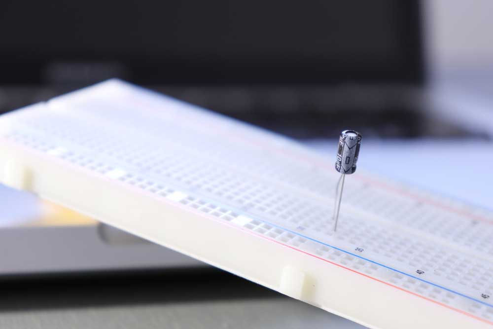
An electrolytic decoupling capacitor
Functions of Decoupling Capacitors
Decoupling capacitors have the following functions.
Eliminate High Frequencies
The primary function of a decoupling capacitor is to eliminate high-frequency interference like RF signals, which can get into devices via electromagnetic radiation.
Usually, these capacitors sit between the VCC and ground pins on the circuit boards of high-frequency devices to filter out AC noise frequencies.
Supply DC Power to Active Devices
As explained earlier, the constant on/off switching in active devices generates a high-frequency noise that goes into the power line. Since a decoupling capacitor can store and discharge energy, it forms a DC power supply circuit that delivers energy to the active device. This supply suppresses electrical noise propagation by leading the noise signals to the ground.
Voltage Stabilization
Decoupling capacitors operate like uninterruptible power supplies, preventing excess current from flowing through the IC in case of a voltage spike.
Types of Capacitors for Decoupling Tasks
The primary factors to consider before picking a decoupling capacitor are the AC signal's lowest frequency and the resistor's value. Considering that, the ideal decoupling capacitors include the following.
Electrolytic Capacitors
Large electrolytic capacitors in the 1-100 µF range are ideal for decoupling low-frequency noise. These units should not be more than two inches from the IC because they store energy and release it instantaneously.
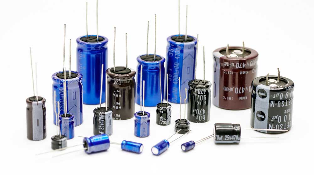
Electrolytic capacitors
But their polarized nature implies they cannot handle over 1-volt of reverse bias without experiencing damage. Additionally, they have relatively high leakage currents, although these leakages depend on the following.
- Electrical size
- Design
- Voltage rating vs. applied voltage
However, the leakage currents do not affect decoupling significantly.
Aluminum Electrolytic Capacitors
These capacitors are ideal for decoupling in low and medium-frequency electronic circuits. They are available in a wide range of capacitance values, have a high capacitance-volume ratio, and are affordable.
Aluminum electrolytic capacitors
However, they have a high equivalent series resistance at low temperatures and experience temperature-related wear. AE capacitors are typical in consumer electronics.
Tantalum Capacitors
Tantalum capacitors have high capacitance values and are less susceptible to temperature-related wear. Additionally, the units have higher capacitance-volume ratios and lower equivalent series resistance than aluminum electrolytic capacitors.
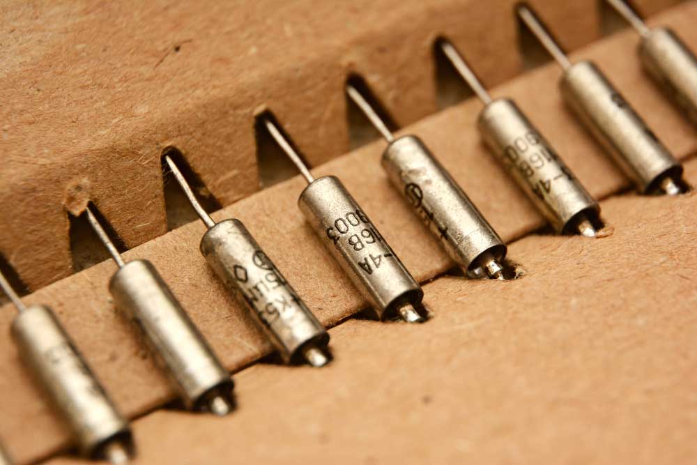
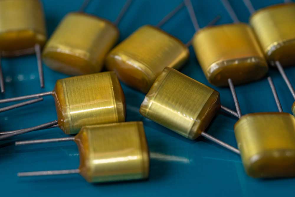
Solid tantalum capacitors
On the downside, tantalum capacitors are costly and limited to low voltage applications not exceeding 50V. They are common in applications requiring high reliability.
Surface Mount Ceramic Capacitors
Low inductance ceramic capacitors in the 0.01-0.1 µF range are suitable for decoupling high-frequency noise from the power supply. The tiny units connect to the IC's power supply pin directly and come in several µF value ratings with high voltage ratings (up to 200V) and high dielectric constants.
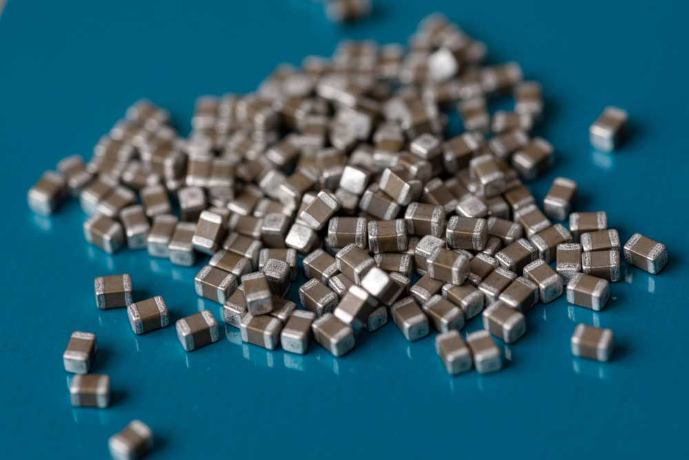
Surface mount ceramic capacitors
These units have a low loss, wide temperature tolerance, and low equivalent series resistance (ESR). Additionally, they are reliable, stable, and can withstand a wide voltage range.
Surface Mount MLCC (MultiLayer Ceramic Capacitors)
MLCCs feature a low inductance design that makes them ideal for bypassing and filtering at 10MHz. They are available in broad capacitance-value and package ranges, all suitable for decoupling in high-frequency circuit designs.
Film Capacitors
Film capacitors like Teflon, polypropylene, polyester, and polystyrene have limited applications because they are expensive to build. However, they are less susceptible to wear and are ideal for high current/voltage and audio signal decoupling applications.
Polyester film capacitors
What is a Bypass Capacitor
Bypass and decoupling capacitors have multiple similarities, which explains why most people use the terms interchangeably. Bypass capacitors shunt AC noise signals, filter them above a specific frequency or eliminate all the AC signals.
These capacitors are ideal for removing unwanted signals in input signals or power supply voltages of analog and digital circuits. Therefore, their applications include the following.
- DC to DC converter
- Clearing audio between amplifiers and loudspeakers
- High pass and low pass filters
- Signal coupling and decoupling
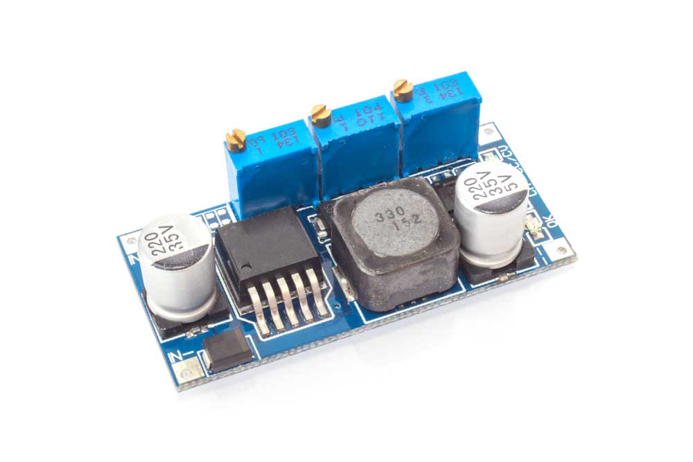
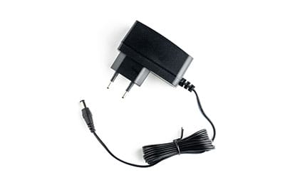
A DC to DC converter. Note the capacitors
Special Offer: Get $100 off your order!
Email sales@ourpcb.net to get started!
Differences Between a Decoupling and Bypass Capacitor
Although most people use the terms interchangeably, bypass and decoupling capacitors have a few differences.
Bypass capacitors shunt high-frequency noise signals in the input signal of the previous stage circuit.
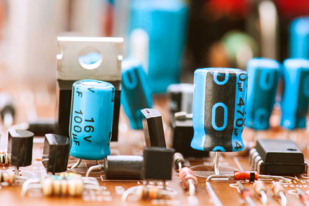
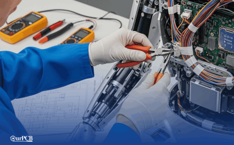
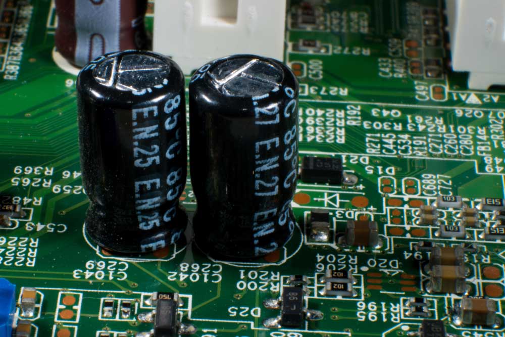
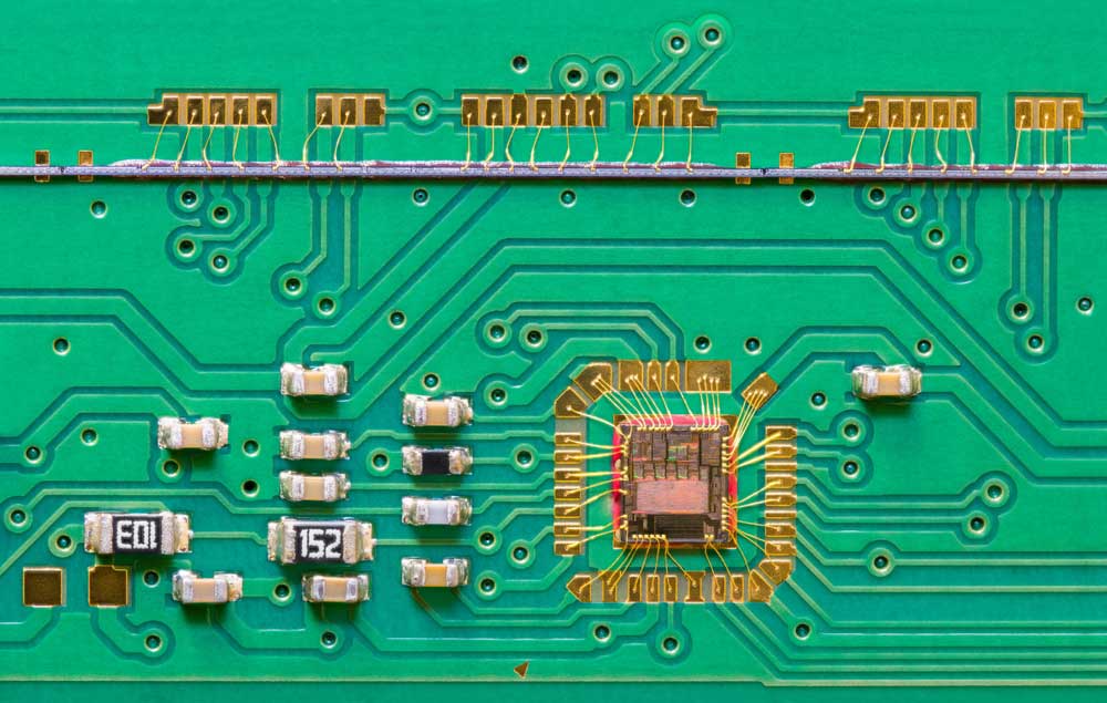
Capacitors mounted on a circuit board
On the other hand, decoupling capacitors smoothen the output signal, stabilizing it to prevent interference from returning to the power supply.
You can use a single electrolytic capacitor for shunting (bypassing) but smoothing the output signal requires two capacitor types.
How To Choose a Decoupling Capacitor's Value
The number of decoupling capacitors used in a circuit depends on the number of ground & power pins and present I/O signals. You should pick the type of capacitor with enough self-resonant frequencies based on the operating frequency or signal bandwidth.
Understanding Self-Resonant Frequency
A decoupling capacitor remains capacitive up to the self-resonant frequency, then turns to an inductor above this frequency. The unit's impedance hits the lowest value at this frequency.
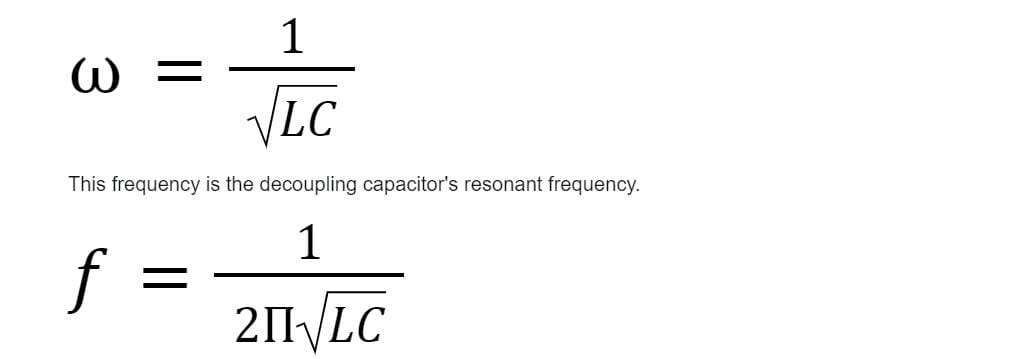
Lower capacitance and inductance yield a higher resonant frequency. Tiny surface-mount components have a lower parasitic inductance, which gives them a higher self-resonant frequency.
Ideally, the low-frequency decoupling capacitor value should lie between 1-100 µF. On the other hand, the high-frequency range for noise decoupling capacitors should be between 0.01-0.1 µF.
Remember to keep the following factors in mind.
ESR and ESL
ESR and ESL imply Equivalent Series Resistance and Equivalent Series Inductance, respectively. Since the capacitor should provide instantaneous current, pick one with a low ESL and ESR.
Package Size
Tiny capacitors shorten the loop size, giving a lower loop inductance.
How To Choose a Decoupling Capacitor's Size
You can determine a decoupling capacitor's size based on the following factors.
Digital PDN
Positioning the capacitor correctly and calculating the precise capacitor size based on the Power Distribution Network's impedance & required charge by the switching IC minimizes noise and ripples. The calculation requires the following formula.
Surface-mount capacitors on a PCB
However, this formula is only valid if the signal bandwidth does not exceed the self-resonance frequency. The signal bandwidth formula is:
0.35/Signal Rise Time
Analog PDN
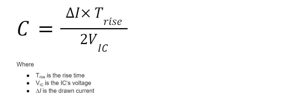
The decoupling capacitor charges and discharges continuously to provide stable power to an analog IC. The formula below gives the capacitor's size in this analog setup.
The drawn current is an increasing function of the frequency and IC voltage.
PDN Impedance
Decoupling capacitors operate effectively above a specific frequency range. The impedance of such a capacitor decreases linearly with a frequency decrease, and vice-versa is true. Parasitic inductance causes an increase in impedance.
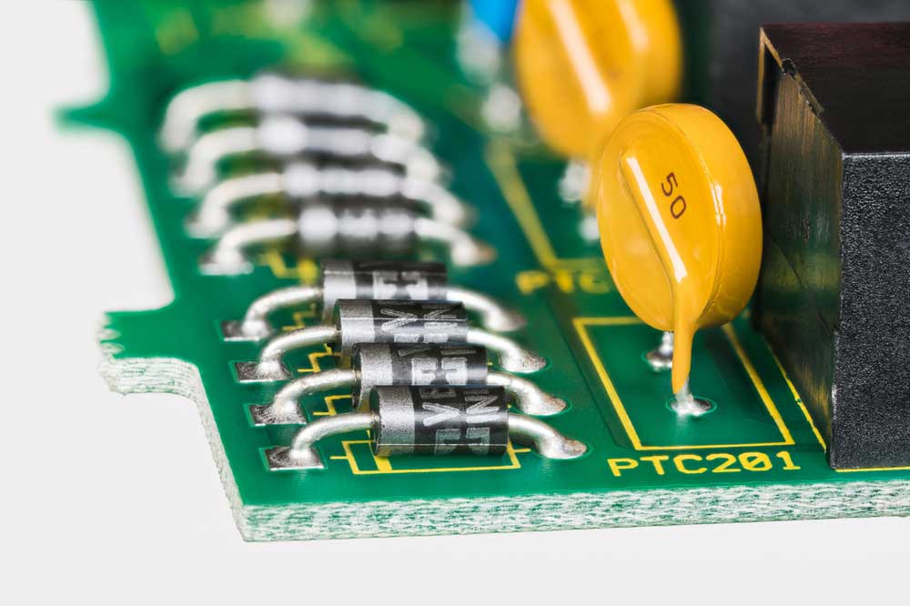
Through hole capacitors mounted on a PCB
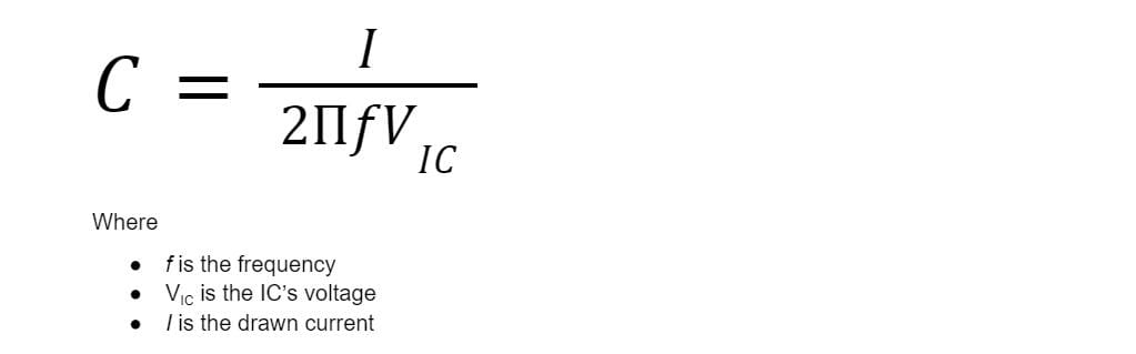
You can determine the decoupling capacitor's size based on the target PDN impedance using the following formula:
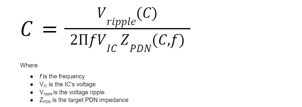
PDN ripple voltage and target PDN impedance are functions of the capacitance. Therefore, solving the problem is complex because calculating capacitance requires several iterations.
However, the formula above is accurate because it incorporates the resonance frequency effect of the decoupling capacitor, which occurs due to parasitics.
When calculating different target PDN values for C and f, we get the best C value to arrive at the lowest target PDN for all frequency ranges.
The IC's datasheet provides the exact decoupling capacitor value to use.
How To Choose a Bypass Capacitor's Value
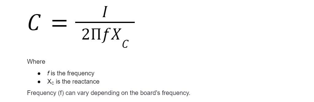
The capacitor's reactance should be a tenth or lower than the resistance in parallel. Current tends to follow the path with the lowest resistance, so the capacitor should have a lower resistance if you want to switch the AC signal to the ground. Use the following formula to calculate the bypass capacitor's value.
Wrap Up
In conclusion, decoupling capacitors are instrumental in the performance and reliability of electrical circuits. Therefore, you should calculate their values accurately before doing the circuit design. That's it for this article. If you have any questions or comments, contact us for further clarification.
Special Offer: Get $100 off your order!
Email sales@ourpcb.net to get started!