When transmitting information from various data lines over a single output line, what do you do? We use Multiplexers to decrease the number of output cables and memory to store data, among many other uses.
Multiplexers are crucial in stepping up data transfer to specific times or bandwidths, making them essential components in printed circuit board (PCB) design. But that's not all there is to know about Multiplexers.
Here at OurPCB, we have a team of professionals eager to tell you more about circuits and how PCB assembly integrates these vital components. Today's article will explore various Multiplexers, their configurations, and applications in modern electronics manufacturing. Read on to find out more!
What Is a Multiplexer IC?

Fig 1: A DVD Player With a Remote Control
A Multiplexer IC is an electronic component that selects data input signals and combines them into a single output channel.
For example, it allows you to select particular audio from a DVD player, CD player, or TV. The analog or digital signals then transmit at a higher speed.
They are made of transistors and relays in analog circuits. In digital applications, Multiplexers are made from logic gates.
An example is the single-pole multiple-position switch used to execute high-speed switching in electronic circuits.
Special Offer: Get $100 off your order!
Email sales@ourpcb.net to get started!
Multiplexer IC Pin Configuration
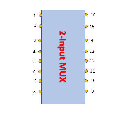
Fig 2: A 2-Input Multiplexer Pinout
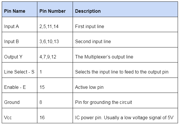
The table below shows the various Multiplexer pins and their uses.
Different Types of Multiplexer ICs
2-Input Multiplexer
A 2-input Multiplexer has one control line (we'll call it "S") to control which input connects to the output.
The inputs, I1 or I2, connect to a standard NAND gate which acts as an SPDT.
SPDT or single pole double throw switches have one input and control two outputs. Ensure to ground or earth the 2-input Multiplexer IC for regular operation.
The 2-input Multiplexer truth table can be shown as follows:
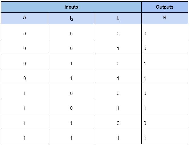
The input line I1 data passes through the Multiplexer when the select input S is HIGH, when input A is binary LOW, the input I2 data transfers to line R and blocks line I1.
Setting A to logic 0 or 1 allows controlling the exact input line to transmit data to the output.
A 2-input Multiplexer circuit Boolean equation is shown below
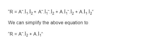
Since it's only possible to have one control line, a 2-input Multiplexer controls two input data lines.
To control more extensive Multiplexer circuits, connect several 2-input Multiplexers. The 2-input Multiplexer circuit is the building block of more extensive Multiplexer circuits.
4-to-1 Channel Multiplexer
A 4-to-1 channel Multiplexer circuit has four input lines or pins and one output data pin or line.
We'll label the four input lines A0, A1, A2, and A3 for our Multiplexer circuit below.
The select lines shall be a and b.
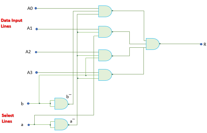
Fig 3: Schematic Diagram of a 4-to-1 Channel Multiplexer
Below is the truth table for the Multiplexer
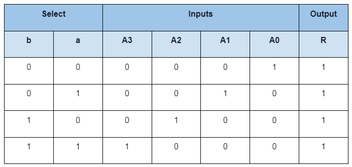
We can see that only one analog switch closes at any particular time while the other three remain open.
The Multiplexer’s Boolean equation is:
"R = a‾b‾A0 + ab‾A1 + a‾bA2 + abA3”
No matter the input lines you connect to the Multiplexer, each select line connects only one input to the output. Therefore, including more control lines allows Multiplexers to control more inputs.
For our case, selecting input A1 to R output requires the input to be HIGH or "1" for line a. Similarly, we'll need line b to be logic "0".
N select/control lines will control 2n data input lines. For example, two select lines will control 4 data input lines.
To implement a 4-to-1 Multiplexer, use seven individual basic logic gates. Check the setup is in the following section.
4 Channel Multiplexer using Logic Gates
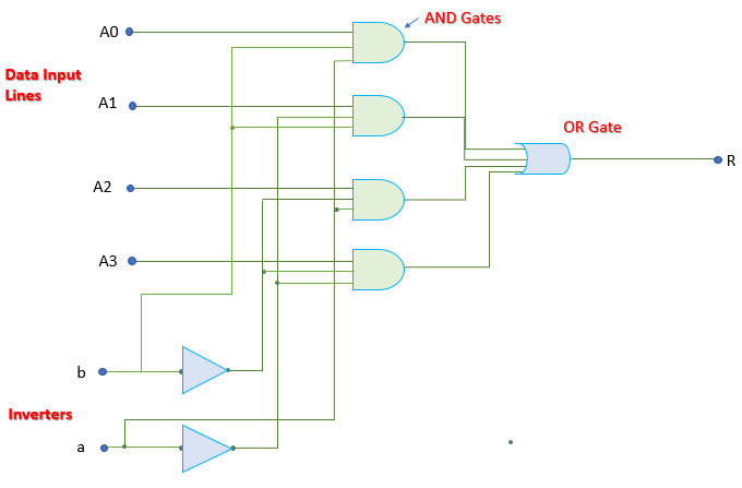
Fig 4: Schematic Diagram of 4-to-1 Multiplexer Using Logic Gates
4-to-2 Channel Multiplexer
4-to-2 Multiplexers have 4 data input lines and two output lines. Therefore, they're an example of multiple output Multiplexers.
It shows that Multiplexers aren't necessarily multiple input single output devices.
Additionally, there are other types of Multiplexers, such as the 8-to-3 and 16-to-4 Multiplexers. The four input lines transmit data through only two output lines.
You can connect other Multiplexer circuits to the 4-to-2 Multiplexer to have more extensive Multiplexer circuits.
8-to-1 Multiplexer
An 8-to-1 Multiplexer has 8 data channels or lines and a standard output channel or conduit. The input lines are A0 to A7.
Also, we can find the number of input select lines using the formula 2n.
For n input lines, an 8-to-1 Multiplexer must have three data input selector control lines C0, C1, and C2.
The Multiplexer selects the output depending on the select line combinations.
The truth table is as below.
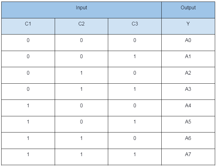
We can have the 8-input Multiplexer Boolean equation from the truth table below.
“Y = C0‾C1‾ C2‾ A0 + C0 C1‾ C2‾ A1 + C0‾ C1 C2‾ A2 + C0 C1 C2‾ A3 + C0‾ C1‾ C2 A4 + C0 C1‾ C2 A5 + C0‾ C1 C2 A6 + C0 C1 C2 A7”
An 8-to-1 Multiplexer logic circuit has 8 AND gates, 7 NOT gates, in addition to 1 OR entrance. Setting the enable pin to 1 disables the Multiplexer, while setting it to 0 allows data selection.
Multiplexer IC Applications

Fig 5: Satellite Space Station
- Network lines
- Communication systems to maintain vast amounts of memory
- Telephone network systems to integrate multiple audio lines for transmission
- Transmission of data from satellites back to earth
- Small memory controllers
- Computer memories
Conclusion
In conclusion, you can see that the construction of Multiplexers is quite simple. However, don't let its simplicity trick you into thinking it isn't essential.
Multiplexers are crucial components for network, computer, and communication systems.
If you need help with your project or some gray areas regarding Multiplexers, please contact us. We'll respond as fast as we can.
Special Offer: Get $100 off your order!
Email sales@ourpcb.net to get started!