EMI design is critical for reducing electromagnetic field radiations.
Electronic devices and traces emit certain levels of electromagnetic waves that can interfere with other electronic systems or circuits nearby.
Such interference is worse if it originates from the same circuit board because it will be a permanent problem unless you change the board to a better one.
So it is vital to develop an EMI design, and we will explain the design guidelines you can use to avoid these noise signals. Take a look!
Contents
What Is EMI?
EMI (Electromagnetic Interference) is the noise disturbance caused when radio frequency energy transmits through conduction or radiation from one electronic device to another.
This disturbance corrupts the signal quality and can cause a malfunction. EMI can occur at any frequency range, but it typically happens above 50MHz. Applying proper PCB design techniques, outlined in these best practices for layout and design, can help mitigate EMI effectively.
Special Offer: Get $100 off your order!
Email sales@ourpcb.net to get started!
Sources of EMI
There are two types of electromagnetic interference: conducted and radiated emission.
The former enters the system via power cables and input lines.
But radiated emissions occur due to electromagnetic waves emitted from communication & power lines, electrostatic discharges, and switching devices.
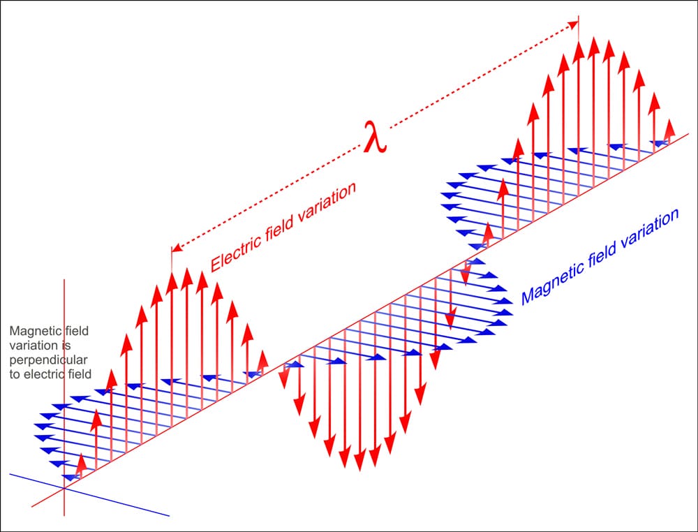
Electromagnetic waves
These waves propagate through the air from the source to corrupt the signal quality of other sources.
One example is mobile phones affecting aircraft communication signal quality.
Electromagnetic emissions can also come from the following.
- High-frequency traces
- Ground planes
- Power planes
- Poor decoupling practices
- Impedance mismatching
Such practices can create unintentional currents like differential-mode and common-mode currents.
EMI vs. EMC
EMC is an acronym for Electromagnetic Compatibility and is the ability of an electronic device to operate within an electromagnetic environment without creating excessive EMI to nearby systems.
So EMC ensures devices or systems perform as required under the outlined safety measures.
It is vital to control EMI during the initial PCB design phase to ensure it doesn't deviate from the outlined standards, causing EMI/EMC to dominate the device performance.
And while it is possible to control EMI in later stages of production, it can be costly.
So you need effective signal integrity solutions to create an EMC-friendly PCB design in the early production stages, which includes the electronic circuit design, board layout, and component selection.

EMC measurement on a PCB using a near-field probe
EMC-Compliant PCB Design Perspectives
You can call a PCB EMC-compliant if it meets the following standards.
- Does not interfere with other systems
- Is not sensitive to emissions from other systems
- Does not have internal interference
EMC and EMI Design Guidelines
As a high speed PCB manufacturer, these guidelines will help you create a board with zero or low EMI.
Separate Sensitive Components
Always group components according to the signals they operate on, such as digital signals, power supply, low speed, analog signals, high speed, etc.
This grouping will ensure the signal tracks for every component group travel in a defined area.
And you can use a filter when a signal must flow between the component subsystems.
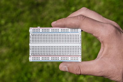
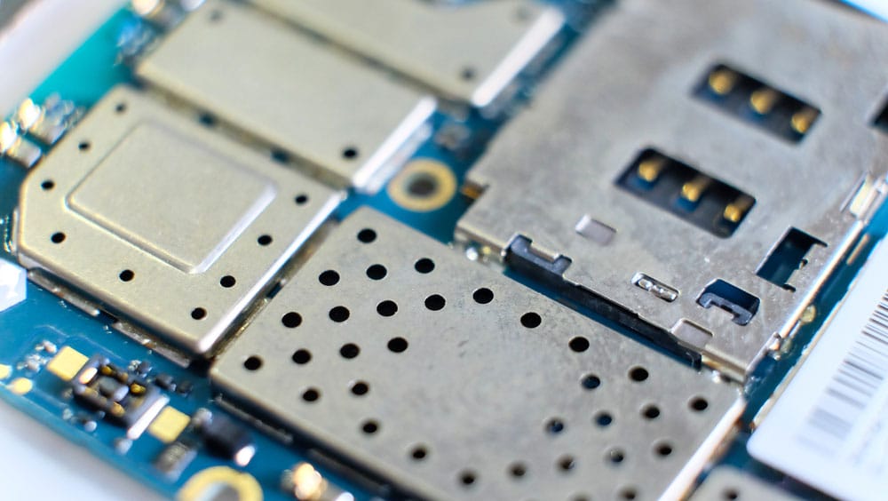
A circuit board with surface mount and thru-hole components
Another crucial point is that using SMD components reduces EMI significantly more than thru-hole components because they give a lower inductance.
Additionally, these components are tinier, allowing for higher-density placement with effective noise control.
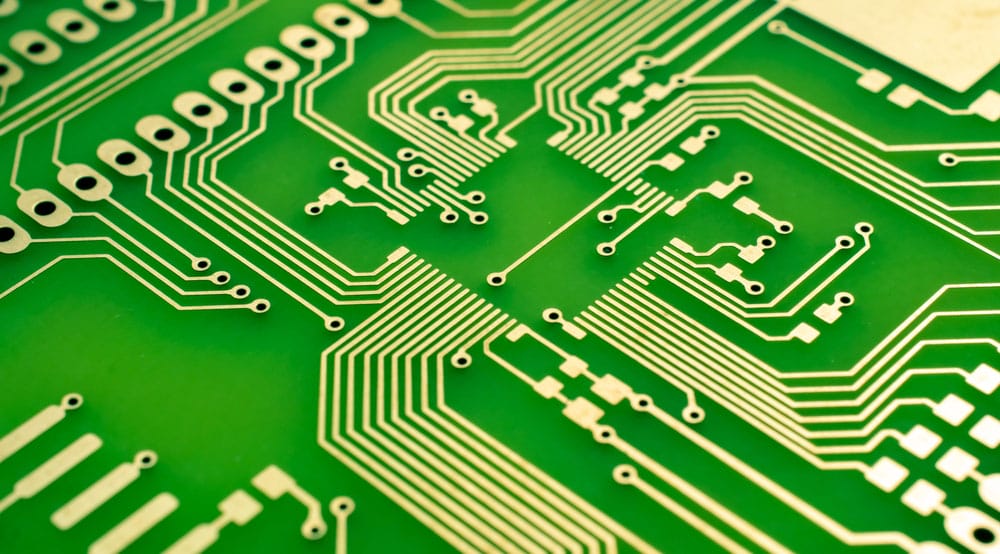
Trace Layout and Spacing
Traces are the conductive copper lines that carry current from drivers to receivers in a circuit board. Implement the following guidelines with traces.
3W Trace Separation
Signal traces, like audio, clock, and video paths, should not be close to other copper lines.
The general rule of thumb is separating them using 3W spacing, where W is the trace width.
This spacing reduces crosstalk and coupling between adjacent traces in the same board layer. But don't apply this rule to differential traces.

Separated traces on a PCB
Closely Router Differential Traces
Routing these traces with minimal separation increases the coupling factor, keeping common-mode noise.
The interference in such cases will cancel out, which explains why the preferred layout for high-speed signals is as differential pairs.
Avoid 90° Turns
A trace's capacitance increases when it encounters a 90° bend because it changes the characteristic impedance value, causing reflections. So use 45° turns instead.
PCB traces with 45° turns
Avoid Vias Where Possible
introduce inductance and capacitance effects that cause impedance mismatching between the trace and connecting holes. So try to avoid them by placing critical copper lines on the same layer.
But if you cannot avoid them, position the ground vias near the signal vias to minimize the changes in characteristic impedance values.
With differential pairs, use the same number of vias for both electrical lines with a common anti-pad to reduce parasitic capacitance.
Use Shunt and Guard Traces for Clock Lines
Decoupling capacitors are essential for stopping EMI propagation on the supply rails.
Shunt and guard rails can safeguard these lines from EMI sources to keep the clock signals from creating noise in the circuit.
Avoid Stubs in High-Frequency and Sensitive Traces
Stubs generate reflections and can introduce a fractional wavelength to the circuit.
Shielding
The mechanical shielding technique uses magnetic, conductive, or both materials to block noise from penetrating the system.
Shields are closed-loop containers that link to the ground, effectively reducing the loop antenna size by reflecting and absorbing a portion of the radiation.
So these containers prevent external noise and data loss.
A microchip and electrical components are covered using a shield on a PCB
Cables transmitting digital and analog signals also generate EMI, which you can prevent by shielding them and connecting them to the ground (back and front).
Ground Planes
Ground planes should have low inductance values to mitigate EMI problems. And increasing the ground area minimizes the ground inductance, which reduces noise and crosstalk.
So use these design practices when dealing with the ground plane.
Use Full Ground Grids and Ground Planes
Using an entire ground layer plane gives the lowest inductance value when the signal path returns from load to source.
However, you can only implement a complete ground plane as a dedicated layer in multilayer boards with three or more layers. So use ground grids in two-layer circuit boards.
Keep Return Paths Short
Long return paths form ground loops that create radiating antennas. Short ones are better because they have a lower impedance, resulting in a more EMC-compliant real-world PCB design.
So always connect the device's ground pin to the ground plane directly.
Use Faraday's Guard Ring To Isolate Noisy Environments
A Faraday guard ring consists of several vias connecting to the ground plane on the PCB edges. These vias restrict noise in the area surrounded by the grounded vias.
While implementing this design, remember to place low-speed circuits close to the power plane and high-speed circuits close to the ground plane.
Ground Copper Fill Areas
Ground all floating copper areas to prevent them from acting as antennas emitting electromagnetic noise.
Be Cautious With Split Apertures
Split apertures consisting of wide vias and long holes in ground and power planes form non-uniform areas that increase impedance in these planes.
Look for Multi-Power Requirements
Circuits requiring more than one power supply should have a ground plane separating the power layers.
With single-layer PCBs, you can run the ground and power traces for one power pin separate from the other.
This design will also prevent noise coupling.
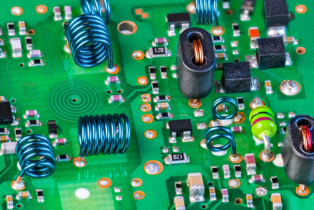
Decoupling Capacitor
switch current at high frequencies, resulting in a switching noise in the connected power traces. This noise can radiate emissions if left uncontrolled.
The best way to reduce this EMI is to place decoupling capacitors close to the chip's power pin and ground it using a direct link to the ground pin/plane.
Also, consider using power planes instead of power traces to minimize EMI.
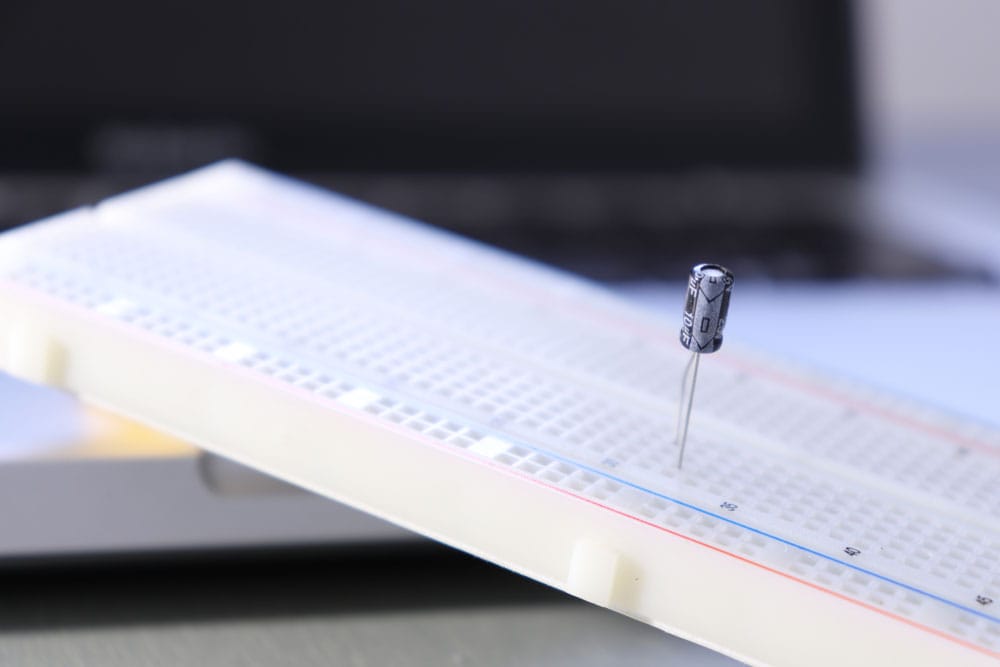
A decoupling capacitor
Transmission Line Controlled Impedance
is critical between source and destination if a circuit operates at high speed.
If mismatched, it will cause high-frequency ringing and signal reflection that can radiate to other sections in the circuit board.
Signal termination strategies can minimize these effects and slow the signal's quick-rising & falling edges.
PCB Layer Arrangement
with more than two layers should have a dedicated ground plane, with the power layer directly underneath. For instance, a 4-layer board should have the layers arranged as follows.
- Signal1
- Ground
- Power
- Signal2
If it has more than four layers, position them as follows.
- Signal
- Ground/Power
- Signal
- Ground/Power
- Signal
- Ground/Power
- Signal
But you can't have a dedicated ground plane with dual-layer boards. In such a case, use ground grids instead. And the grids should run parallel to the power traces.
Conclusion
In conclusion, EMI designs are critical to enabling electromagnetic compatibility when building printed circuit boards.
And as you can see, you should implement multiple design guidelines to ensure the board is EMC compliant.
If you encounter any challenges implementing these guidelines or need help testing the EMC/EMI designs, contact us, and we'll be happy to help.
Special Offer: Get $100 off your order!
Email sales@ourpcb.net to get started!