Just like the other components on a printed circuit board (PCB), a capacitor polarity will have distinctive polarities, both positive and negative. Understanding how to identify capacitor polarity is essential as you build your circuit board from scratch. However, not all capacitors have polarity; the ones that do have one trick up their sleeve.
Above all, polarity ensures that only one terminal acts on the voltage applied. To gain an edge when linking capacitor polarity in your PCB design, it’s crucial to know the fundamentals of circuit board assembly. This article will educate you more on capacitor polarity. By the end, you should have a better idea of why it is crucial to understand capacitor polarity in your PCB manufacturing and assembly processes.
Contents
- 1. What is Capacitor Polarity?
- Importance of Observing Capacitor Polarity
- To Prevent Electrical Hazards
- To Prevent Circuit Malfunction
- To Maximize Efficiency and Durability
- Polarity Markings on Capacitors
- Positive and Negative Markings
- Color Coding
- Arrow or Indented Band
- Different Pin Lengths
- Chamfered Edges or Dashes
- How To Determine the Capacitor Polarity
- Visual Identification
- Using a Multimeter
- Checking the Datasheet
- Checking the Package
- Some Capacitors Do Not Have Polarity
- Types of Non-Polarized Capacitors
- Common Applications of Non-Polarized Capacitors
- Polarity of the Electrolytic Capacitor
- The Advantages of Electrolytic Capacitors
- What are the Disadvantages?
- The Application of Electrolytic Capacitors
- Comparing the Non-Polarized Capacitors and Polarized Capacitors
- What Happens after Reversing the Polarity of a Capacitor?
- Summary:
1. What is Capacitor Polarity?
A capacitor consists of parallel thin metal sheets separated by a dielectric material.
The two thin metal sheets work as the electrodes, while the dielectric is the insulator.
Insulation is vital because it acts as a partition between the electrodes.
The standard symbol of a capacitor is a clear depiction of this inside structure.
The dielectric could be either rubber, paper, ceramic, or glass. On the other hand, the thin metal sheets consist of either tantalum, aluminum, or silver.
Carbon nanotubes are sometimes a better option owing to their better conduction features. Initially, capacitor polarity is proof of symmetry in a capacitor.
But first, you have to know how balance works.
A non-polarized capacitor will still work like it should, regardless of how you connect it to your circuit.
It doesn't matter what lead goes where. It is a clear case of non-symmetry.
On the other hand, a polar capacitor is highly sensitive when placing it on a circuit board.
Often, a capacitor will have two terminals, though you may see some with more than that.
A polarized capacitor only works if the placement sticks to the vital outline rules.
What this means is that placing the element on the circuit should be in one direction. Putting the capacitor in the wrong way will end in disaster.
The capacitor could blow or fail to work as you'd like. Therefore, a capacitor should be on your list of concerns when building a circuit.
If you want to weld work on PCB or breadboard constructing circuits, this method is the most accurate.
Importance of Observing Capacitor Polarity
To Prevent Electrical Hazards
Connecting the terminals of a polarized capacitor to the power supply in reverse can create an overvoltage condition where the voltage exceeds its rated value.
Overvoltage conditions can damage the capacitor's conductive plates or dielectric material, causing it to leak hazardous chemicals. It can even explode.
The leaking chemicals can damage the adjacent components on the PCB or even pose a risk to you as the user.
On the other hand, explosions can burn other parts of the PCB, destroying it beyond repair.
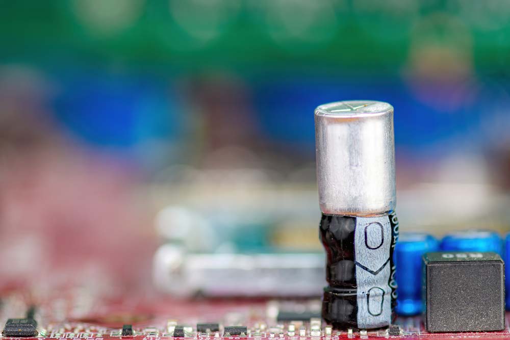
Capacitors mounted on a PCB
To Prevent Circuit Malfunction
The circuit will malfunction if the reverse terminal connection damages the capacitor because the current will not flow through to other parts as intended. Alternatively, the circuit can exhibit reduced performance if the electric current flows partially.
To Maximize Efficiency and Durability
Reversing a capacitor’s polarity can increase leakage currents or cause total failure. Either of these cases reduces the device’s efficiency and durability.
A blown capacitor
Polarity Markings on Capacitors
Positive and Negative Markings
The most common polarity markings on capacitors are the positive and negative signs, which are pretty straightforward. Plus (+) indicates the positive terminal, while minus (-) labels the negative terminal.
A capacitor with a gray line with the negative sign (-)
Color Coding
Some capacitors feature color-coded terminals or sides to indicate their polarity. For instance, radial surface-mounted capacitors have a small black-colored section on the top to indicate the negative terminal side. The other section (usually gray) indicates the anode (positive pin).
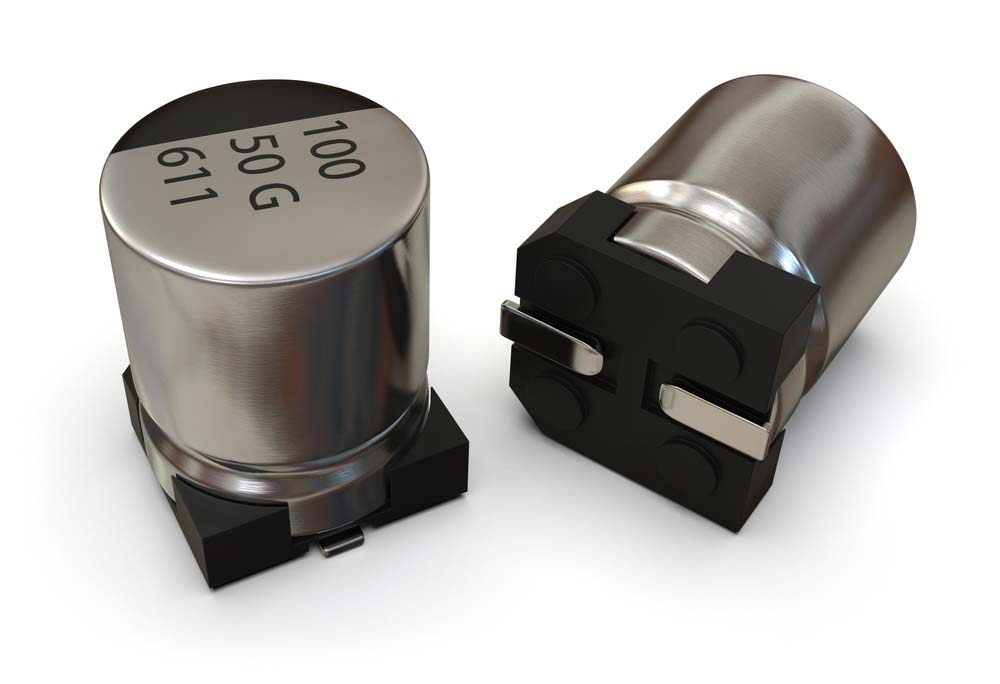
A surface-mount capacitor with one side painted black
Radial through-hole capacitors also have some color coding in the form of a gray line running down the negative side of the device’s black body.
Arrow or Indented Band
Axial capacitors with color-coded lines on one side usually have arrows pointing to the negative pin. They can also have indented bands on the positive terminal side.
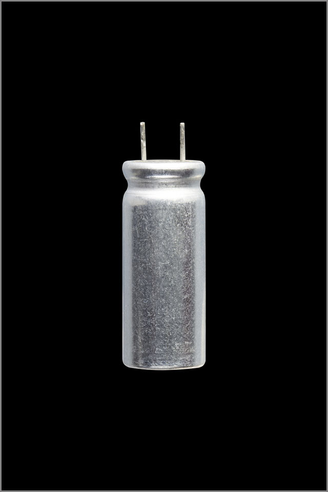
Different Pin Lengths
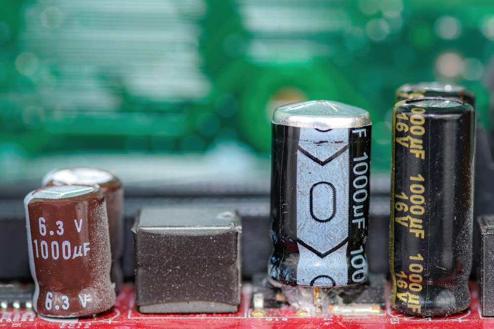
In addition to having a line running down the negative side, radial through-hole electrolytic capacitors usually have a longer positive lead than the negative pin.
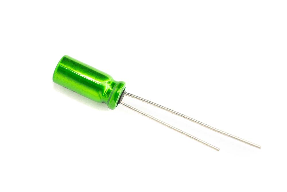
An electrolytic capacitor with a short and long pin
Chamfered Edges or Dashes
Some solid tantalum axial capacitors usually feature chamfered edges on the positive lead end.
On the other hand, tantalum electrolytic capacitors can have dashes, a plus sign, or both to indicate the positive polarity side.
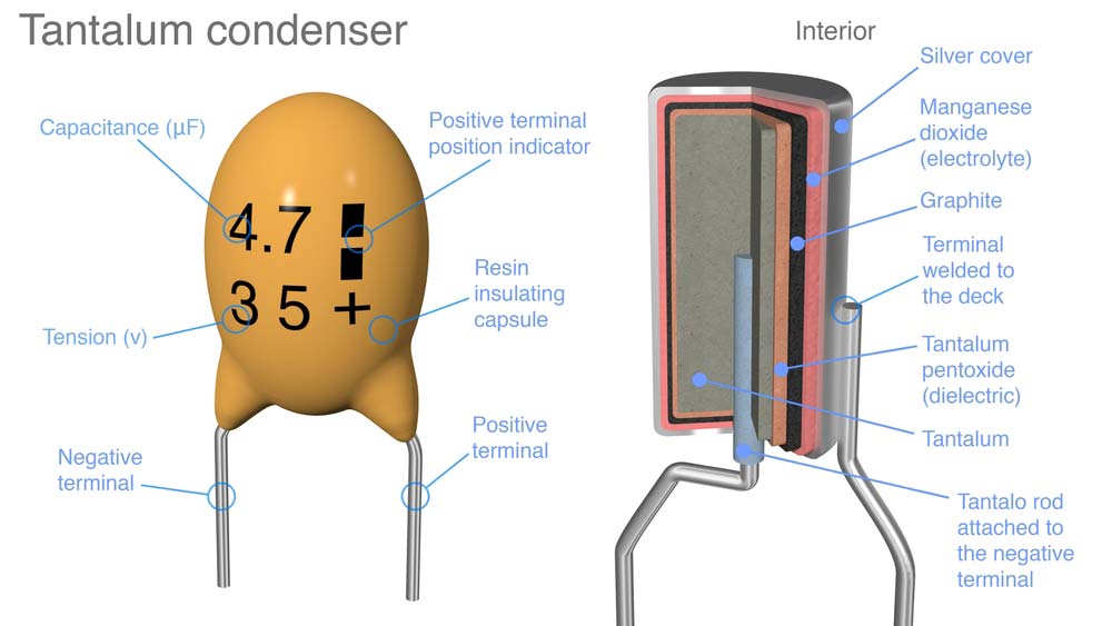
A tantalum capacitor with dashes and a positive sign to indicate polarity
Special Offer: Get $100 off your order!
Email [email protected] to get started!
How To Determine the Capacitor Polarity
You can determine a capacitor’s polarity using either of these four methods.
Visual Identification
All polarized capacitors have polarity markings, which differ depending on the capacitor type. These markings include positive/negative signs, color codes, arrows, chamfered edges, different pin lengths, etc.
Using a Multimeter
The current flowing through a capacitor is small if you connect the anode to the multimeter's red probe because of its high leakage resistance.
But if you reverse the connection, the leakage current will be high (low leakage resistance).
You can use this principle to determine the device’s polarity.
Set the multimeter to resistance mode, then connect either pin to the red probe and the other to the black one.
Take the resistance reading, then discharge the capacitor. Reverse the connection and check the reading.
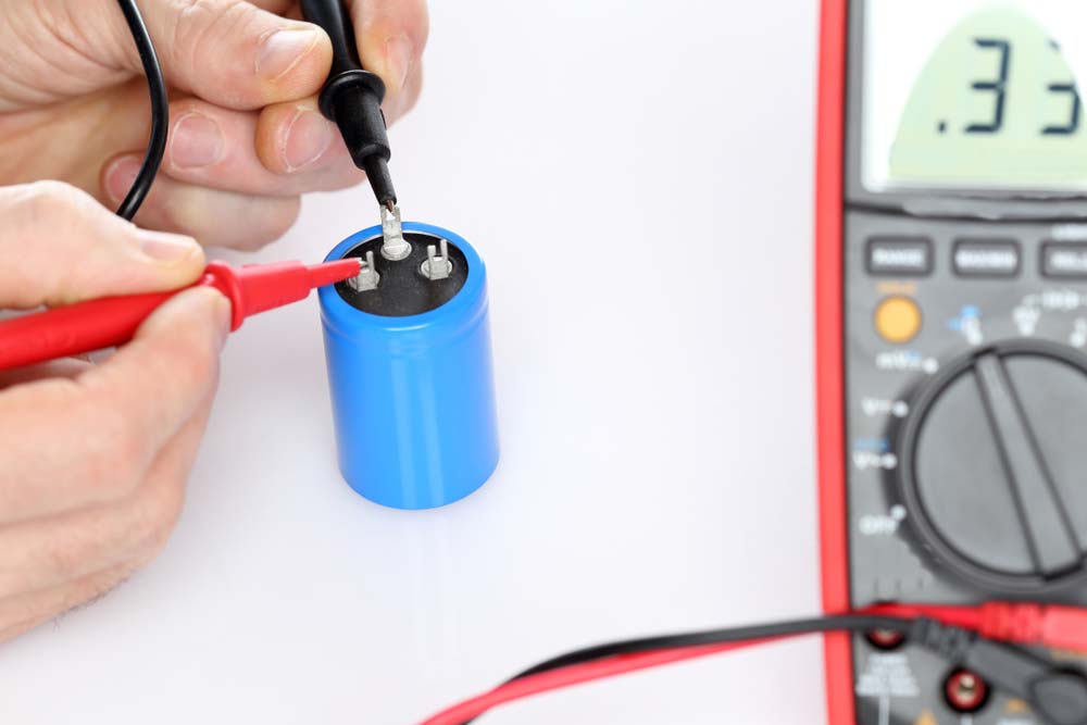
Capacitor testing using a multimeter
The test with the highest reading should have the anode connected to the red probe.
Alternatively, you can set the multimeter to diode mode and measure the voltage drop across the terminals.
When connected positive to positive and negative to negative, the polarized capacitor should have a 0.6-0.7V voltage drop. In reverse, the voltage should not drop or be out of range.
Checking the Datasheet
The capacitor’s datasheet should indicate the device’s polarity information, including the visual markings you can spot on the component.
Checking the Package
Check the device’s packaging if you can’t find the polarity information on the datasheet.
Some Capacitors Do Not Have Polarity
Ideally, there are two types of capacitors: polar and non-polar capacitors. Polar capacitors have either or both negative and positive ends.
On the contrary, non-polar capacitors have no distinct lots. You can randomly insert these capacitors in your PCB without considering what lot goes where.
Even so, there will not be any adverse impact on your circuit or ruining of your components.
These designs are quite familiar with coupling and decoupling circuits, oscillation circuits, compensation, and feedback circuits.
In the ideal case, polarity shouldn't exist in a capacitor. However, that isn't practical, mostly where large capacitance is vital.
In such a case, unique materials make up the body of the unit. Ultimately, this is the reason that they end up having a distinct capacitor polarity.
Notable examples of such polar capacitors are tantalum electrolytic capacitors, electrolyte, and aluminum capacitors. Non-polar capacitors are often small in size since the large ones are tough to fabricate.
On the one hand, polar capacitors can only work in a circuit where the voltage acts in one direction, i.e., DC voltage.
Non-polar capacitors, however, can work even with AC voltage, where voltage works for both sides.
For this reason, non-polar capacitors have a better edge due to their ability to work with AC voltages.
Since capacitor polarity isn't an issue, non-polar capacitors can replace polar capacitors in a circuit.
The only rule here is to make sure that the working voltage and capacity values are the same.
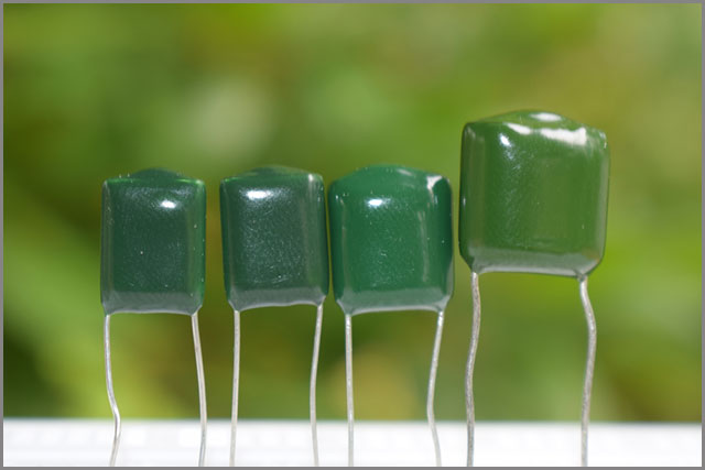
(Non-Polarized Capacitors)
Types of Non-Polarized Capacitors
Here are the most common examples of non-polarized capacitors:
- Polyester capacitors
- Glass capacitors
- Film capacitors
- Polystyrene capacitors
- Mica silver capacitors
- ceramic capacitors
Common Applications of Non-Polarized Capacitors
- In signal filtering to enhance signal quality by eliminating unwanted frequencies
- High-frequency circuits because they deliver reliable and consistent capacitance across different frequency ranges
- Radio-frequency circuits that require fine-tuning, such as antenna-matching systems
- Timing circuits (like oscillator networks) to control the operation duration and frequency.
Polarity of the Electrolytic Capacitor
- Aluminum Electrolytic Capacitors-These types of electrolyte capacitors have an aluminum structure acting as a valve. After applying a positive voltage through the electrolyte fluid, a metal oxide layer forms. This oxide layer is now an insulator that takes the place of a dielectric.
Polarization occurs on the oxide layer preventing the flow of electric charge. Aluminum electrolytic capacitors have manganese dioxide as the cathode, with aluminum making up the anode.
(An aluminum electrolytic capacitor )
- Niobium and Tantalum Capacitors-Tantalum electrolytic capacitors are ideal for surface-mount gadgets more common in medical, military, and space applications. By having tantalum as the anode, oxidation is relatively easy, similar to aluminum electrolytic capacitors. Tantalum has high conductivity, mostly when in contact with a wire. As soon as the oxide forms on the surface, there is more room for charge storage.
Niobium capacitors work by oxidizing the material in a wire to create an insulator. The insulator acts as the dielectric with a much higher permittivity compared to tantalum-based capacitors. They are now quite popular since they are less costly than their tantalum counterparts.
The Advantages of Electrolytic Capacitors
- Electrolyte capacitors rely on the formation of an oxide layer about capacitor polarity. The oxide is a much more reliable dielectric with stimulating effects. For this reason, these units can achieve high levels of capacitance than the other capacitors. Here are some of the other benefits.
- Size-Tantalum capacitors are the most popular capacitors. The other types are prone to gaseous breakdown. The capacitance that is possible is higher in comparison to non-electrolyte units. The non-electrolyte capacitors would have to be larger to achieve the same capacity.
- Greater Capacitance-When it comes to volume, electrolyte capacitors can achieve high capacitance for small work. As such, there are very few non-electrolyte capacitors with over ten MFD of capacity.
What are the Disadvantages?
When it comes to electrolyte capacitors, there is always the risk of current leaking. The leakage can, at times, be relatively high. They also have a much shorter life-span.
The Application of Electrolytic Capacitors
Since capacitor polarity is a crucial factor in electrolyte capacitors, using them demands a great deal of care. Incorrect placement means that you will not obtain precise results and could trigger an explosion of the unit. They are also quite sensitive to temperature, which is why you need to factor in the thermal conditions. e
These capacitors are ideal for reducing voltage ripples from a power source for their filtering properties. They are also mostly preferred in tasks requiring large capacitance, such as filtering high-frequency signals.
Comparing the Non-Polarized Capacitors and Polarized Capacitors
The idea behind the working of both nonpolar and polar capacitors is the same. Generally, they all work to store and release electric energy. Consequently, the voltage levels can't change suddenly.
When comparing elements with capacitor polarity and those that don't, apparent differences stand out. Below are some of the differences between nonpolar and polar capacitors.
-
The Dielectric Material
Polar capacitors have electrolytes as the primary dielectric, which helps achieve a high capacitance. The dielectric in the structure is what mainly dictates the amount of capacitance possible.
It also sets the level of voltage that the capacitor can withstand. On the other hand, those without polarity use a metal oxide layer as the dielectric substance. Polyester is another compound that can work as a dielectric.
-
Capacitor Performance
The performance of any electrical component is what finally shows the accuracy of your circuit. You may find that some power supply units need a metal oxide dielectric capacitor as a filter. In such a case, your best option would be a polar capacitor, often above 1 MF.
Its performance is what makes it ideal for filtering, coupling, and decoupling. In comparison, a non-polar capacitor is usually below 1 MF. Its performance makes it a perfect choice for frequency selection, resonance, and as a current limiter. Thus, by lacking capacitor polarity, this unit has a limit when it comes to other circuit functions.
-
Capacitance
Since nonpolar and polar capacitors use different dielectric structures; their capacities can’t be the same. It doesn't matter if they have equal volumes. Therefore, an opposing unit can be of a higher capacitance than a nonpolar one.
-
Structural Appearance
Capacitor polarity will often determine the shape of a capacitor. The main factor here is the element's point discharge. For electrolyte polar capacitors, you will find that most of them take a circular shape. Finding squared ones is quite rare. Depending on how you intend to use it in a circuit, a capacitor can either be rectangular, tubular, sheet, or circular.
-
Capacitor Usage
As mentioned before, polar capacitors can have high capacitance and other elements that render them inadequate for high-frequency operations. Although some can handle high frequencies, such as tantalum capacitors, they can, in turn, be quite pricey.
On the other hand, non-polar capacitors have good high-frequency characteristics and are much smaller. They are relatively cheap but aren't ideal for large capacity tasks.
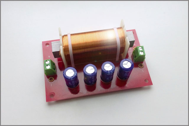
(A capacitor set up in a hybrid low-pass-high-pass filter)
What Happens after Reversing the Polarity of a Capacitor?
The capacitor polarity shows that a polar capacitor needs to be forward-biased. The anode terminal needs to be at a high voltage level for the charge to flow as expected. You could first examine the unit to see the different polarities before connection.
If you happen to connect the unit wrong through reverse polarity, the dielectric will break. The result is a short circuit, making the capacitor overheat, and eventually, the electrolyte fluid leaks.
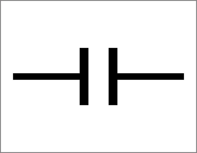
(The Circuit Symbol for a nonpolarized capacitor)
Summary:
In any case, you must know how to show capacitor polarity before placing the unit on a PCB. This approach is the difference between poor results and a functional, solid circuit design.
That’s why capacitor polarity plays a massive role in the production, assembly, and design of a PCB. Here at OurPCB, we are always happy for the chance to interact with you as we gain more knowledge about PCBs.
Special Offer: Get $100 off your order!
Email [email protected] to get started!