The invention of the hybrid integrated circuit in 1958 by Jack Kilby and later the first actual monolithic IC by Robert Noyce in 1959 changed the electronics industry. It brought in a compact and energy-efficient circuit design that is cheaper than those built using discrete electronic components. However, different fabrication techniques evolved in IC manufacturing but two of the most common logic families that came out of the process were TTL vs. CMOS. Invented in 1963 and 1968, TTL and CMOS logic families are quite different. We will look at them in detail below to paint a clearer picture of the technology.
Contents
What is TTL?
TTL is an acronym for Transistor-Transistor Logic, and it consists of a logic family of bipolar junction transistors. These bipolar transistors do both amplification and logic functions, hence the TTL name, and each has multiple inputs & emitters.
There are several types of TTL, which include the following:
- High power transistor-transistor logic
- Low power transistor-transistor logic
- Standard TTL logic
- Fast TTL logic
- Schottky transistor-transistor logic
- Advanced Schottky transistor-transistor logic
These TTL devices also contain resistors, and each type is suitable for particular purposes. For instance, the fast and relatively low-power Schottky. TTL is perfect for charge control and voltage clamping. On the other hand, a radiation-hardened TTL chip is ideal for space applications.
Some TTL ICs examples include the 7402 NOR gate and the 7400 NAND gate.
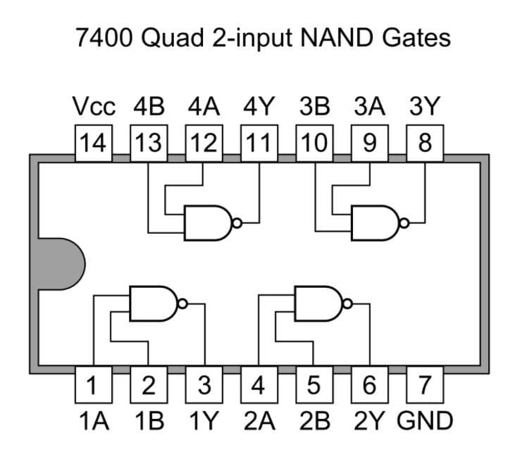
A 7400 Quad 2-input NAND Gate
Source: Wikimedia Commons
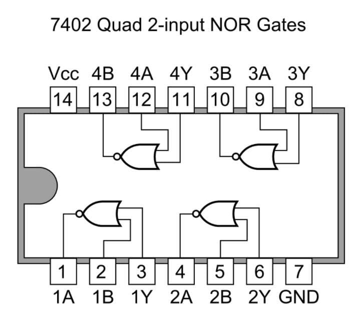
A 7402 Quad 2-input NOR Gate
Source: Wikimedia Commons
TTL vs. CMOS: What is CMOS?
CMOS is also an acronym (Complementary Metal Oxide Semiconductor), but the technology differs from TTL. It employs n-type and p-type metal-oxide field-effect transistors (MOSFET) to do the logical function. These transistors are in symmetrical and complementary pairs, forming a single package as shown below:
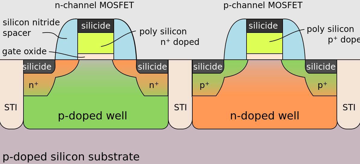
An n-channel and p-channel MOSFET
Source: Wikimedia Commons
Microprocessors, memory chips, microcontrollers, and most digital logic circuits rely on CMOS technology construction. Other applications include transceivers, data converters, image sensors, and other static analog circuits. The CMOS chip also handles the zeros and ones (low and high) plus the logic.
Special Offer: Get $100 off your order!
Email [email protected] to get started!
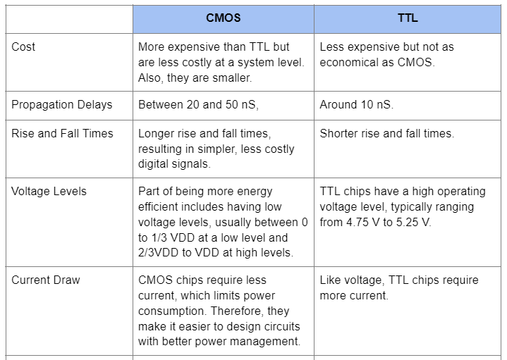
TTL vs. CMOS: The Difference
Back to the beginning, the basic TTL design came into existence in 1963, while CMOS came about five years later in 1968. Since it is newer, it brought about some improvements. The CMOS logic gate circuit is more energy-efficient, produces less noise, and packs a higher density of logic gates.
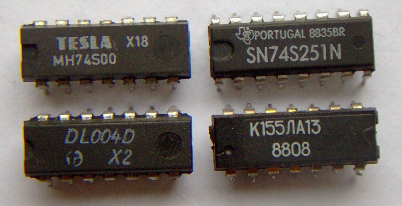
Four TTL integrated circuits
Source: Wikimedia Commons
However, the power consumption in CMOS chips varies depending on several factors. Key among them is the clock rate, whereby a high clock speed raises the power consumption. But generally, CMOS chips are more efficient. Typically, a 1-gate CMOS logic gate circuit will consume 10nW while a 1-gate TTL will consume 10mW (10,000,000nW).
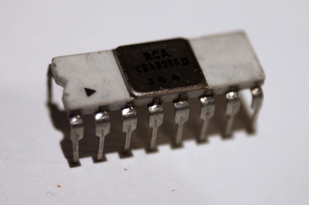
A CMOS chip
Source: Wikimedia Commons
That said, CMOS chips have their disadvantages. For instance, their design and fabrication make them delicate and particularly susceptible to damage due to static electricity discharge. Touching the terminals is enough to damage the chip. Thus, you can damage the unit unintentionally.
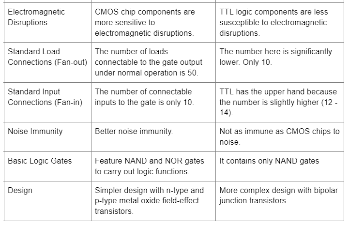
Other differences include the following:
TTL vs. CMOS: Is CMOS A Good Choice Over TTL Component?
From the detailed comparison above, it is evident that CMOS chips have more advantages than their TTL counterparts. They require less power but have a higher output voltage. Also, they are smaller and more economical while being less susceptible to noise. With such immunity, the integrated circuits transmit cleaner signals with low interference.
The difference in propagation delays is not that significant, so signal transmission is pretty quick on both sides. Lastly is the fan-out number. CMOS can connect to a higher load number at the output terminal than TTL. However, CMOS chips are delicate, so handle them carefully.
TTL vs. CMOS: Which Logic Family is Fastest?
CMOS integrated circuits' FETs (Field Effect Transistors) are faster and more energy-efficient than the bipolar junction transistors in TTL chips. Additionally, CMOS ICs have a higher density of logic gates, making them quicker.
However, the CMOS logic family is not the fastest in the market. Emitter-Coupled Logic (ECL) delivers the highest operation speeds due to its relatively small voltage swing. Also, it keeps its transistors from entering the saturation region to maintain performance at the optimum levels.
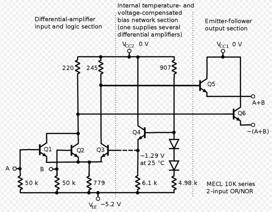
Emitter-Coupled Logic
Source: Wikipedia.
Summary
In conclusion, integrated circuits changed the electronics industries, and the CMOS & TTL logic families are the most commonly used fabrication techniques. Each has its benefits and drawbacks, but CMOS generally has the upper hand in performance.
Therefore, if you need such chips incorporated into your circuit board, get in touch with us, and we will assemble the PCB as per your project requirements.
Special Offer: Get $100 off your order!
Email [email protected] to get started!