Are you looking for a low voltage operational amplifier with limited power consumption? An LM 324 IC is your best bet for such an op-amp. This op-amp requires a minimum voltage of at least 3V and above. Also, if you are looking for an op-amp that requires a single polarity supply, the LM 324 circuit is the best. You may want to know what is the composition of this circuit? If that is your concern, read this elaborate presentation on lm324 circuits. Here are some of the key things that you need to know about these integrated circuits.
Contents
- What are lm324 Circuits?
- What is the characteristic of lm324 circuits?
- lm324 circuits work principle
- Ten applications using LM324 Circuits
- LM324 Inverting AC Amplifier Circuit
- LM324 Non-inverting AC Amplifier Circuit
- LM324 AC Signal Three Distribution Amplifier Circuit
- LM324 Active Bandpass Filter Circuit
- LM324 Temperature Measurement Circuit
- LM324 Comparator Circuit
- LM324 Monostable Trigger Circuit
- LM324 High Sensitivity Sniffer Circuit
- LM324 Responder Circuit
- LM324 Circuits-- OP-amp LED flasher – Oscillator circuits.
- Conclusion
What are lm324 Circuits?
An LM324 circuit is an operational amplifier that you can use in various types of circuits. It features a broad range of power supply options, low static power consumption, and compatibility with a single power supply. This makes the LM324 IC an ideal choice for applications in printed circuit board (PCB) design and PCB assembly, particularly where space and power efficiency are essential.
What is the characteristic of lm324 circuits?
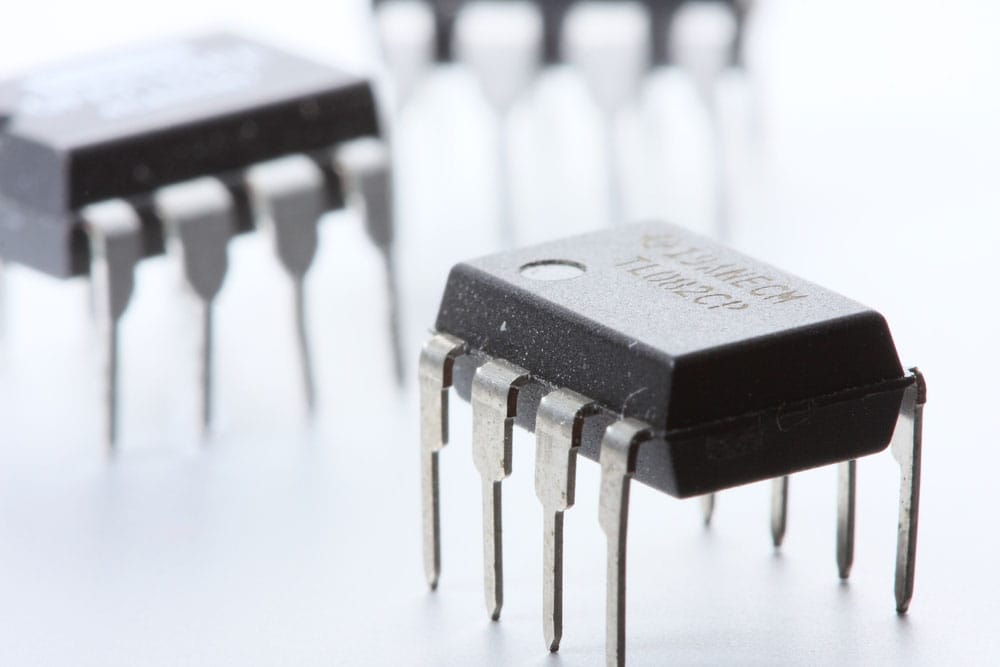
Figure 1: An Op-Amp IC
There are several critical features of lm324 circuits. They include the following:
- They have a wide range of power supply voltages. You can use a voltage from 3V up to 30V. For dual power supplies, the field is ±1.5 V to ±16 V.
- LM324 Op-Amps have low current consumption. You can operate the lm324 circuit with a minimum of 0.8 milliamperes.
- They have a significant voltage gain of approximately 100 dB.
- They have an output current of 8 milliamperes. You can obtain a minimum of 5mA.
- Feature low input biasing current.
- They have a giant voltage swing.
- They have a differential input voltage range that is equivalent to the power supply range.
- The simple circuit has a wide bandwidth of up to 1.3MHz.
- The conventional Op-Amp also features actual differential input stages
- The integrated circuits have four independent amplifiers.
Special Offer: Get $100 off your order!
Email sales@ourpcb.net to get started!
lm324 circuits work principle
All lm324 circuits follow a similar working principle. Application of an input signal to the non-inverting terminal will cause current flows. If the non-inverting input is less than the inverting voltage of the op-amp, the output voltage is zero. In such a comparator circuit, no current is flowing. If you apply a higher input signal than the inverting voltage, the output signal is high. There is an internal pull-up of the comparator circuit. As a result, there is no need to include an external resistor in the circuit.
Ten applications using LM324 Circuits
LM324 Inverting AC Amplifier Circuit

Figure 2: Illustrating the principle of amplification
In this application, you use the amplifier in a transistor in an AC amplifier circuit. You can also use this integrated circuit for the preamplification of the amplifier. You do not necessarily need to debug the circuit for it to function. Also, when using this amplifier, you require a single power supply. During operation, you connect the input signal to two resistors. These are pivotal in forming a 1/2V+ bias. Another crucial component of the power supply is a suppression capacitor.
Additionally, you can easily calculate the amplifier voltage amplification factor of this AC amplifier circuit. For this, you only need the resistance of the external resistors. The ratio of external resistors will give you the amplification factor of the AC amplifier circuit.
Noteworthy, the resistance of one of the external resistors is equal to the input signal source resistance. Also, the resistance is equal to the magnification you intend to achieve in the AC amplifier circuit.
LM324 Non-inverting AC Amplifier Circuit

Figure 3: A Motherboard
For this circuit, you will have an amplifier with a high input impedance. During operation, you connect the input signal to two resistors for this circuit. This will create a 1/2V+ voltage divider circuit. As a result, the AC Amplifier Circuit creates a bias to the Op-Amp via the third resistor.
Also, you can easily calculate the amplifier voltage factor (Av) for this circuit. All you require is the external resistance of the resistors. In this case, you obtain the circuit input resistance from the third resistor. There is also a fourth resistor in the circuit, connecting in series to the external resistor. The resistance of this resistor is very high, usually in the range of thousand ohms.
LM324 AC Signal Three Distribution Amplifier Circuit

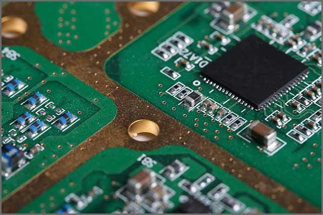
Figure 4: A circuit board
It is one of the most important op-amps. You can use it to divide the AC signal into three output voltages. With these voltages, you can opt to use them in a myriad of ways. For instance, you can choose to use them for analysis, control, and indication, among other uses. One of the key upsides of this system is that the splitting has no significant impact on the signal source.
One of the Op-amps will have a high input resistance. Due to this property, you should connect this Op-Amp to the negative input terminal of the other. Consequently, you should connect the input signal to the positive input terminal. You will achieve an external resistance equivalent to zero on the input terminal.
In this connection, you must ensure that the circuit is in same-phase amplification. Therefore, you will have a voltage amplification factor of 1 for every amplifier. As with the other AC amplifier circuit (s), there are resistors that create the 1/2V+ bias. This makes a three distribution output system.
The system blocks the input and output capacitors during this operation.
LM324 Active Bandpass Filter Circuit
Figure 5: An Integrated Circuit
This circuit is commonplace with audio devices. You can use it as a band-pass filter to select frequency band signals. On this circuit, you will find light-emitting diodes. These indicate the magnitude of the signal amplitude via a display.
One of the key upsides of this circuit is that you can connect it to a single power supply. All you need is to bias the positive input of the system to 1/2V+. Also, you need to connect the resistor to the positive terminal of the amplifier.
LM324 Temperature Measurement Circuit

Figure 6: A thermometer
In this system, you connect the temperature probe made of a silicon triode 3DG6 to a diode. You will witness an emitter junction voltage change when the temperature rises. Also, during connection, you should ensure the amplifier is in an in-phase DC.
When the temperature increases, there is a voltage drop in the transistor. It results in a decline in the non-inverting input voltage of the Op-amp. Consequently, the voltage at the output will decrease.
To obtain a reading, connect a processing circuit. With this setup, you will create a linear amplification. It will also help you to perform other automatic controls.
LM324 Comparator Circuit

Figure 7: A Circuit Board
A comparator circuit primarily consists of a system that compares output voltages. You use it, for example, to compare output in a system with different voltages. There are several components in an LM324 comparator circuit. They include output pins, reference voltage, sensor voltage, and the ground.
When you remove the feedback resistance of the Op-amp, the open-loop magnification of the system will tend to infinity. Consequently, you will create a voltage comparator with a high or low input. The Op-amp will give you a low-level output if the positive input voltage is higher than the negative.
LM324 Monostable Trigger Circuit
There are two main resistors, which create a voltage divider circuit. This circuit is responsible for the creation of bias voltage at the negative terminal of the amplifier. The system also comprises key components such as a capacitor, a diode, and another resistor.
During operation, when there is a low input voltage, a current passes through the diode. It prompts the capacitor to discharge, which in turn causes the input voltage to fall. You can use this circuit in automatic control systems.
You can create a power delay function in this circuit by removing the diode. The operational amplifier output in this circuit depends on the difference in the bias voltages.
LM324 High Sensitivity Sniffer Circuit
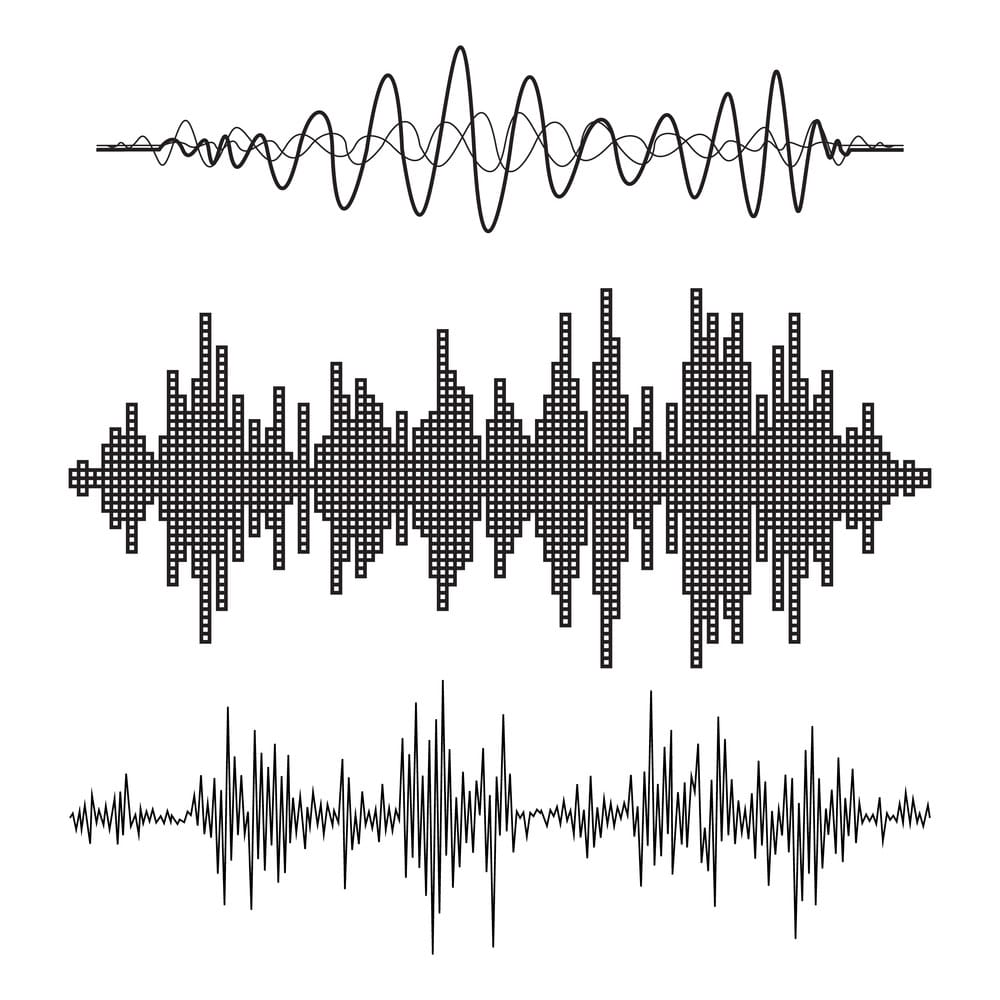
Figure 8: A Sound wave illustration
You can use this circuit in the detection of weak sounds. Its primary property is high sensitivity and directivity. The fundamental aim of an amplifier is to improve the quality of sound.
Therefore, during use, you install a microphone to a tube in this circuit. This collects sounds from a particular direction. Next, the tube will submit the sound to the amplifier for amplification.
The amplifier will amplify the sound in two main stages. First, the signal will pass to the first amplifier, which has a gain of 100 times. Secondly, the signal passes to the other amplifier, which has a gain of 500 times. This series of amplifiers ensures that it is possible to amplify very low-frequency sounds. The output in this system is the headphones.
LM324 Responder Circuit
This amplifier utilizes a simple circuit and readily available components. You can apply it in the design and manufacture of an answering device such as a phone. When you transmit a sound signal in this circuit, you pass it via a series of amplifiers. Amplification in this circuit occurs just like in the circuit mentioned above.
LM324 Circuits-- OP-amp LED flasher – Oscillator circuits.

Figure 9: LED Flasher
You can use this circuit to create an alternating system of winking LEDs. During assembly, connect the LEDs in series with their respective resistors. By using the capacitor, you can regulate the frequency of the LEDs. The amplifier will act as the controller of the winking of the LEDs.
Conclusion
We have compiled a list of some of the primary uses of the LM324 circuit Op-amps. The above examples are some of the ways that you can use an LM324 circuit. You can, therefore, choose the appropriate one depending on your use. Also, in case of any query on Op-amps, contact ourPCB, and we will get back to you promptly.
Special Offer: Get $100 off your order!
Email sales@ourpcb.net to get started!