Faults can occur when building complex circuits or during their operational life. Continuity test are some of the best procedures to troubleshoot these issues. There are several ways to do this test, but the multimeter is the most typical device for the task. We will analyze the continuity test in detail and explain how to test various circuit parts using a multimeter. Read on to learn more!
Contents
- What Is a Continuity Test?
- Why Do Continuity Tests?
- Tools Used for Continuity Tests
- Continuity Tester
- Multimeter/Ohmmeter
- Multimeter Continuity Test Procedure
- Capacitance Continuity Test
- Inductor Continuity Test
- Circuit, Cable, and Wire Continuity Tests
- Fuse Continuity Test
- Push Button/Switch Continuity Test
- How To Make a DIY Continuity Tester
- Risks of Introducing Voltages Via Multimeter Leads
- Wrap Up
What Is a Continuity Test?
A continuity test is a procedure used to check the current flow in a circuit to determine if it has a complete path. In simpler terms, the test checks if the current flows freely from one end to the other.
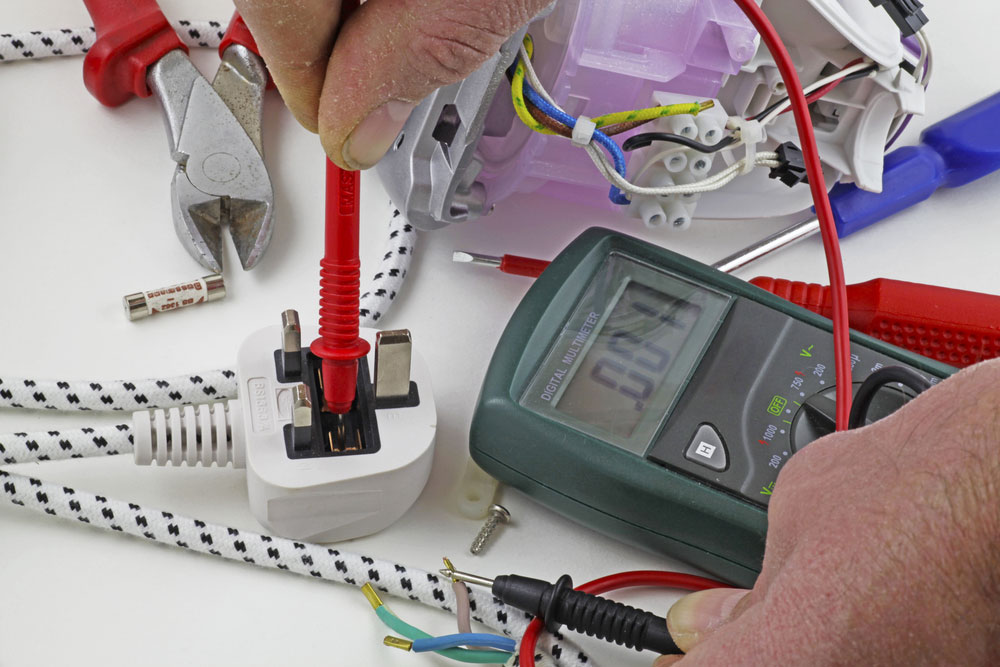
An electrician carrying out a continuity test on a plug’s live cable using a multimeter
Continuity testing involves supplying a small voltage on one end of the circuit between the two test points. The circuit is open if the electric current gets interrupted and does not reach the other end. This interruption could be due to cracked conductors, damaged components, or high resistance. But if there are no interruptions, you have a continuous circuit. If you need of top-notch PCBA services with reliable PCBA testing methods, we at OurPCB are ready to assist you.
Why Do Continuity Tests?
These tests can check the following:
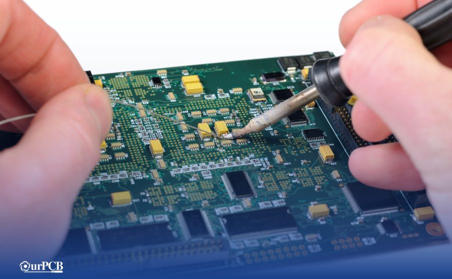
- Soldering quality
- Broken wires (mostly in headphones and power cords)
- Functioning or blown fuses
- Whether switches are operational
- Open or shorted conductors
- Identify damaged components in circuit boards
Tools Used for Continuity Tests
You can use either of the following devices for testing continuity.
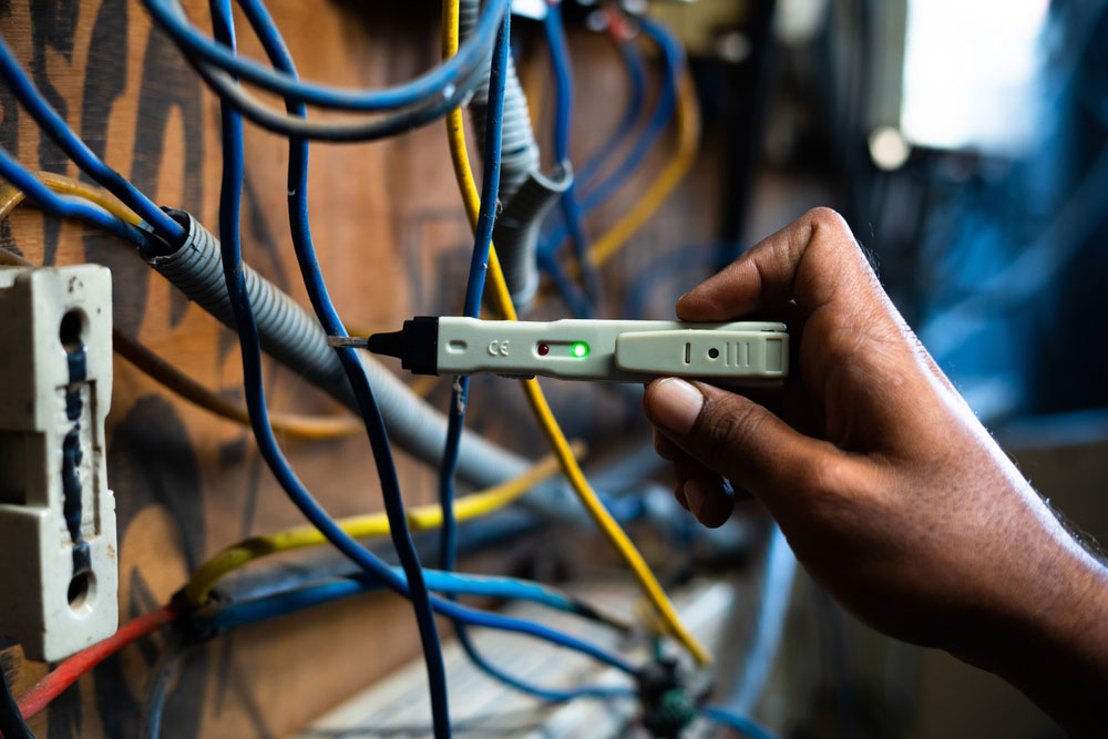
Continuity Tester
Specialized continuity testers are ideal for checking electrical metal pathways. They use a battery as the power source with a metal probe on one end and a wire lead with a metal probe or alligator clip on the other side.
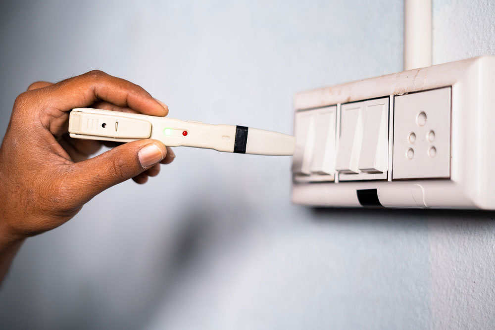
A continuity tester
The device has a simple operation mechanism. If you touch the metal probe and wire lead, you create a closed circuit that will make the buzzer or light go off.
Multimeter/Ohmmeter
A multimeter is a rectangular device with an analog gauge or digital display for testing various aspects of a circuit, not just continuity. Also, it features a dial to select the test mode, which can be:
- Voltage mode (DC/AC voltage)
- Current (amperage)
- Resistance
- Continuity
Like the tester, this device gets its power from a battery.
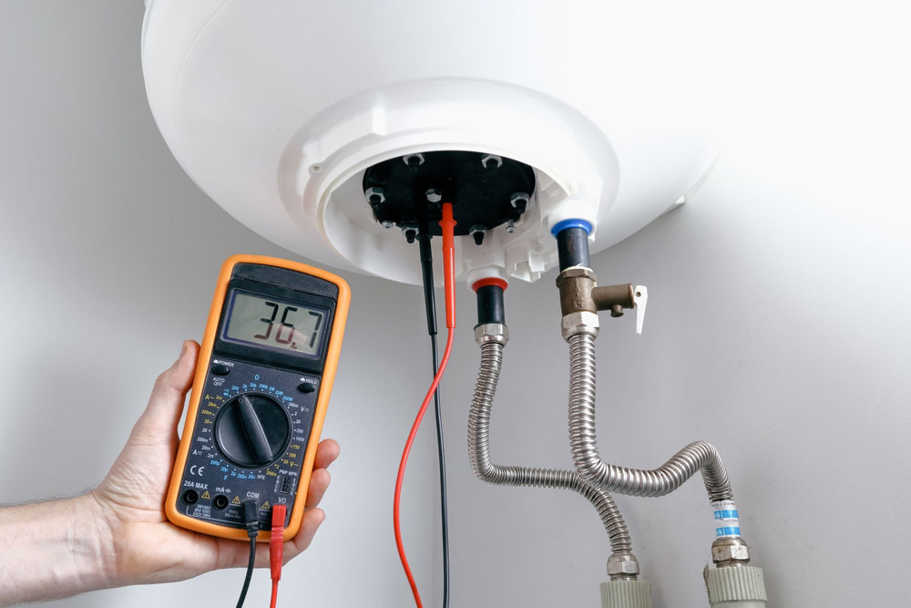
An engineer using a multimeter to test for continuity in a new heating element after installation
Multimeter Continuity Test Procedure
There are two ways to conduct continuity tests using a multimeter.
- Continuity mode
- Resistance mode (ohmmeter)
So here are the procedures to follow when checking for continuity in capacitors and inductors.
Capacitance Continuity Test
You must remove the capacitor from the circuit, then discharge it completely before doing this test.
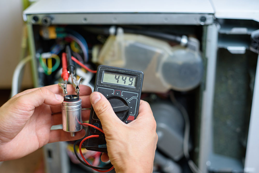
Resistance measurement of the starting capacitor of a dishwasher
Continuity Mode Testing
Set the digital multimeter dial to continuity mode, then plug the black probe into the COM slot and the red one into the mAVΩ port.
Connect the other end of the red probe to the capacitor's positive terminal and the black one to the negative terminal.
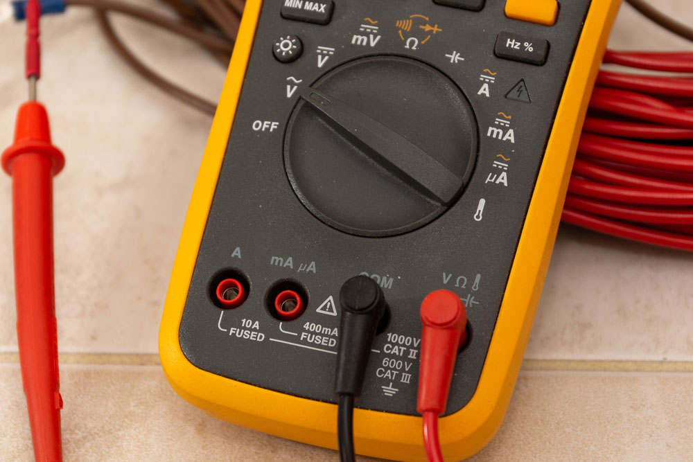
A close-up of a multimeter showing the dial, selectable modes, probes, and four slots
Initially, the multimeter will indicate 0 in the display. But it will charge the capacitor and eventually show OL or infinity after a full charge. This reading can also mean the capacitor is open.
But the reading will initially show infinite resistance (open) or a low value (short) if you have a damaged capacitor.
Resistance Mode Testing
Set the multimeter to resistance mode, then connect the red and black probes, as shown above.
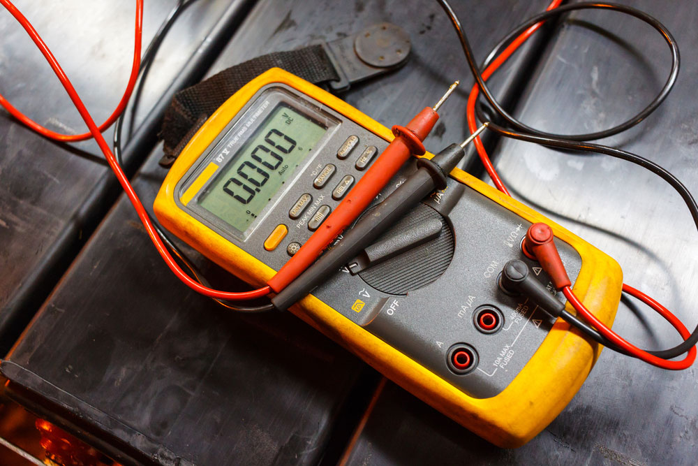
A digital multimeter with red and black probes connected
The capacitor is in good shape if the resistance reading starts from 0, gradually reaching infinity. But a high initial resistance signals a damaged capacitor. And a low resistance means a short capacitor.
Inductor Continuity Test
An inductor is a coil. You must remove it from the circuit before testing the current flowing through it.

A set of copper coil inductors
Continuity Mode Testing
Set the multimeter dial to continuity mode and plug in the probes. Connect the other end of the test probes to the inductor's positive and negative terminals, respectively.
The multimeter should beep if the inductor functions normally, and you will see low readings. But you cannot spot any short turns.
On the other hand, if the inductor has some faults, the multimeter will not beep. Instead, it will indicate OL or 1 to show an open electrical circuit.
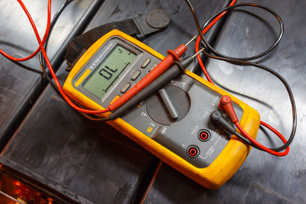
A multimeter reading showing OL (overload)
Resistance Mode Testing
Set the multimeter to resistance mode and adjust it to the lowest possible reading. Connect the probes to the multimeter and inductor terminals.
A low resistance indicates the inductor is okay, while a high initial resistance on the multimeter display indicates a damaged inductor. Keep in mind low resistance that is near zero might also mean the inductor has short turns.
Special Offer: Get $100 off your order!
Email [email protected] to get started!
Circuit, Cable, and Wire Continuity Tests
Continuity testing in cables, wires, and circuits requires the ohm setting to check for resistance in the circuit path. Zero resistance in cables and wires means they are okay. Circuits might have low resistance, which indicates greater continuity. But infinity shows there is no circuit continuity.

An engineer examining a circuit board using a digital multimeter
Fuse Continuity Test
When testing a fuse box, use the ohm setting. A zero reading on the multimeter shows the fuse is in good condition. But an infinite reading indicates a broken fuse.

A technician examining a fuse box using a digital multimeter
Test these devices in "ON" and "OFF" modes using the ohm setting, beginning with the former. The reading should be zero because the circuit pathway is complete. But the multimeter should indicate infinite when the switch/push button is off. If both readings indicate infinity or zero, the switch has a short circuit and needs a replacement.
How To Make a DIY Continuity Tester
If you don't have a multimeter, you can make a continuity tester using the following components.
An electrician testing current flow using a continuity tester
- 9V battery
- Two wires
- Two probes
- Resistor
- Buzzer or LED
Connect them as shown below.
Risks of Introducing Voltages Via Multimeter Leads
Specific components in PCBs cannot handle the 9V that a multimeter or DIY continuity tester delivers across the probes in continuity mode. Usually, such parts can handle such voltages when power runs through the circuit but cannot tolerate it when you switch it off and introduce an external voltage.
So try to minimize the voltage as much as possible when doing the tests. The trick is to use a multimeter in resistance mode at the lowest ohm setting. A lower resistance means the probe voltage will be low.
It is vital to note that most basic multimeters combine diode and continuity testing modes in one. So the voltage must be the minimum required to power LEDs and forward bias silicon diodes, usually 2-3V.
Wrap Up
In conclusion, continuity tests are critical for troubleshooting faults in circuits or circuit components. And you can use the steps above to check your PCB or circuit parts if faulty. That's it for this article. If you have any questions or comments, contact us, and we'll be in touch asap.
Special Offer: Get $100 off your order!
Email [email protected] to get started!