Electronics is one of the most diverse subjects today. There is a lot to learn, whether you do it as a hobby or a career. Almost everything today is electronic; this includes simple household appliances to industrial equipment.
If you have used a detector circuit or divider circuit, chances are, you have come across a comparator. Therefore, to give you a better understanding of the subject, let us dig deeper. Here is a simple introduction to comparators.
Contents
What Is A Comparator?
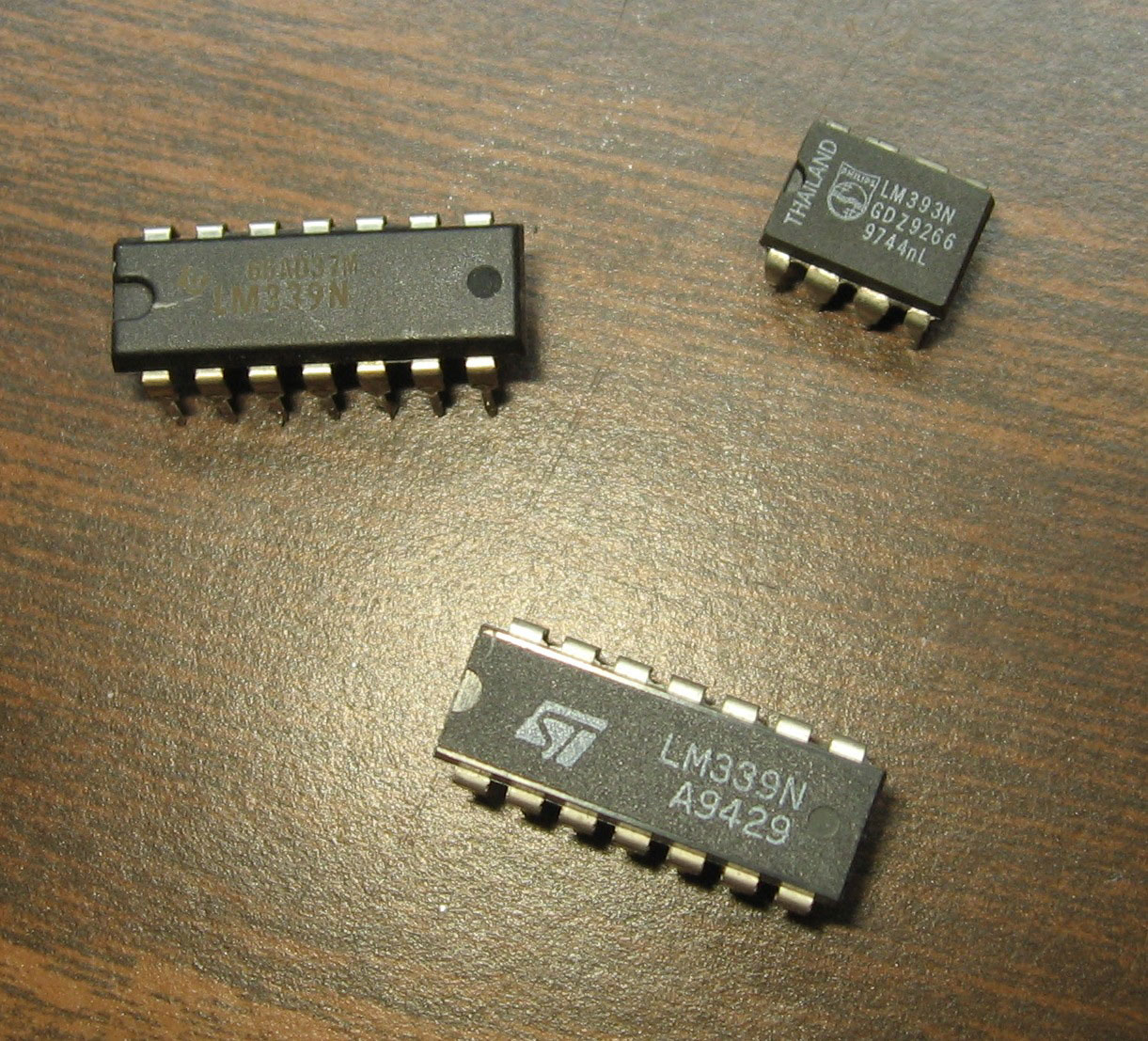
Comparator Chips
Source: Wikimedia Commons
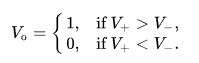
A comparator is a simple device that compares different voltages and currents. Consequently, it has two analog signal input terminals. They generally include the V+ and V- and one binary digital output signal voltage registered as V0. Thus, Comparators are the go-to for detection comparison measurements of voltages and currents. Thus, Comparators are the go-to for detection comparison measurements of voltages and currents.
Subsequently, in every comparator is a high-gain differential amplifier circuit. For that reason, an amplifier circuit is in most devices. It measures and digitizes analog input voltages. For example, relaxation oscillators as well as analog-to-digital converters (ADCs).
When calculating the comparator output, you will be looking at this equation.
Also, a comparator has five main parameters. These are:
- Hysteresis voltage
- Bias current
- Superpower swing
- Drain-source voltage
- Output delay time
Working Principle
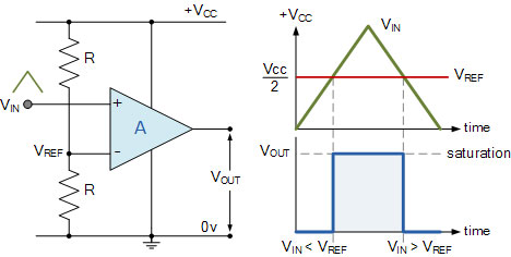
Working principle of a comparator
Source: Wikipedia
Generally, a comparator compares supply voltage and current measurement to determine the biggest. As a result, the voltages or currents are the input signals of the comparator. Once all inputs align, the comparator electronic circuit compares the two and outputs.
Subsequently, the output is either 1 or 0. To begin with,1 indicates the voltage at the positive feedback circuit (high). 0, on the other hand, shows negative feedback (low). You can opt for an operational amplifier circuit to substitute for a comparator. However, an operational amplifier has no negative feedback.
With this in mind, the operational amplifier’s open-loop gain is higher than a comparator. Hence it can only process inputs with a minimal differential input voltage.
In summary, the working principle of a comparator is the conversion of electrical signals.
Special Offer: Get $100 off your order!
Email [email protected] to get started!
Comparator ICS
Here is an overview of the wide range of comparator ICs available on the market today. These ICs include:
- LM324
- LM358
- uA741
- TL081\2\3\4
- OP07
- OP27
In addition, these ICs are in different categories. For example, sigma, optical, electronic, pneumatic, digital, mechanical, and electrical. As a result, the various types of comparator ICs represent their different uses.
How To Build A Voltage Comparator Circuit Using IC 741
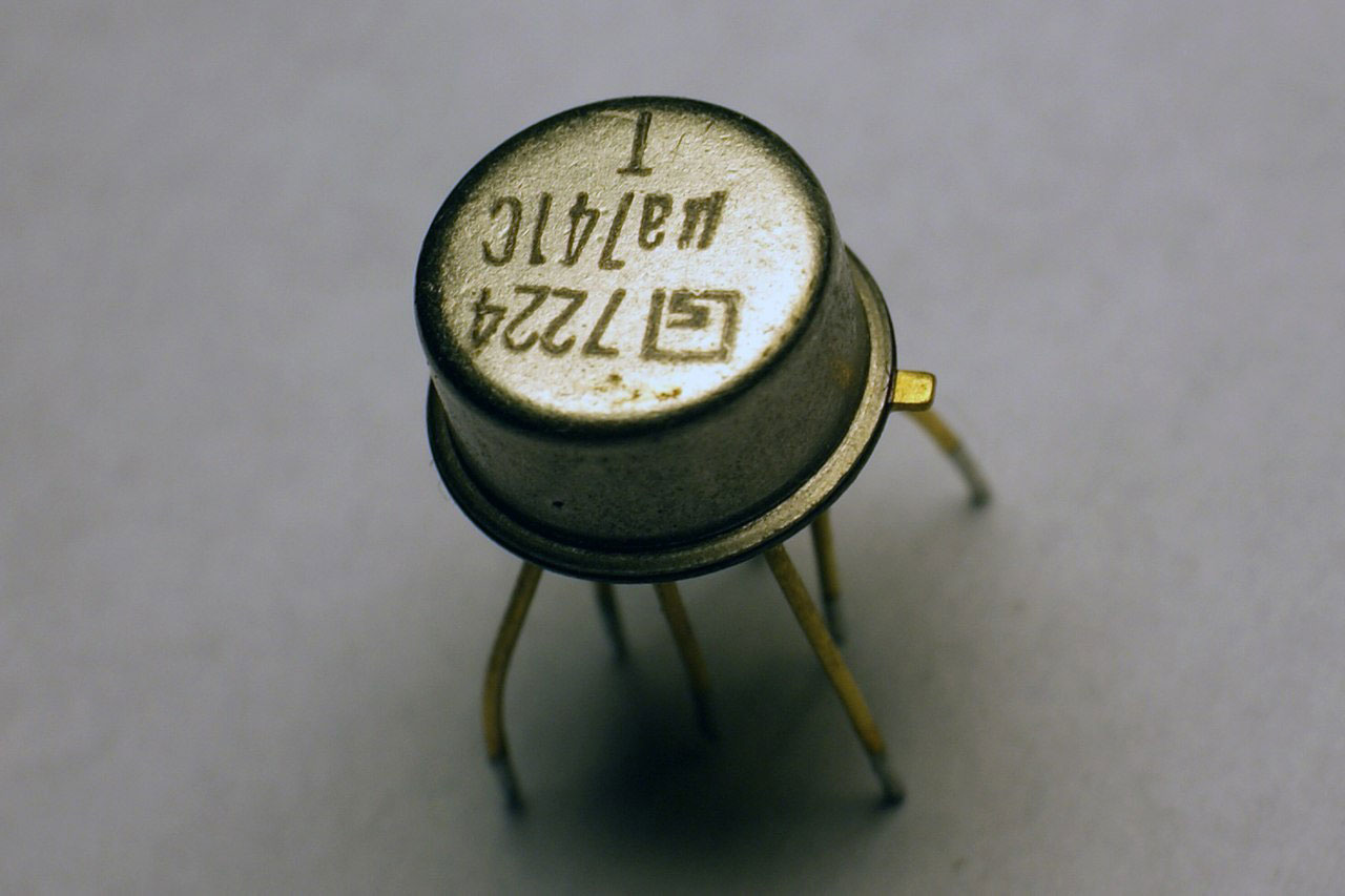
Operational amplifier
Source: Wikipedia
As an illustration, we will be building a night light using an IC 741. Before we jump into the illustration, here is a breakdown of a voltage comparator.
Generally, a voltage comparator is a circuit that compares reference voltage input signals. Moreover, its basic unit forms a non-sine wave generating circuit.
For the most part, comparators are simple interfaces between analog and digital circuits. They are also in conversion circuits as well as waveform generation. Also, voltage comparators come in different forms.
- Single-limit comparators
- Hysteresis voltage range comparators
- Window comparators
- Three-state voltage comparators
Requirements
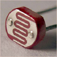
Photoresistor
Source: Wikimedia Commons
- 33KΩ resistor
- 330Ω resistor
- A 10KΩ potentiometer
- LM741 Operational amplifier
- Light Emitting Diode
- DC AAA batteries
LM741 Pinout Breakdown
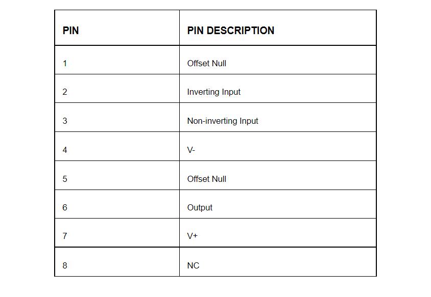
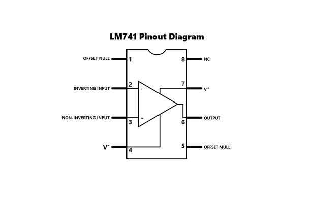
LM741 pinout
Process Of Connecting LM741 To The Comparator Circuit
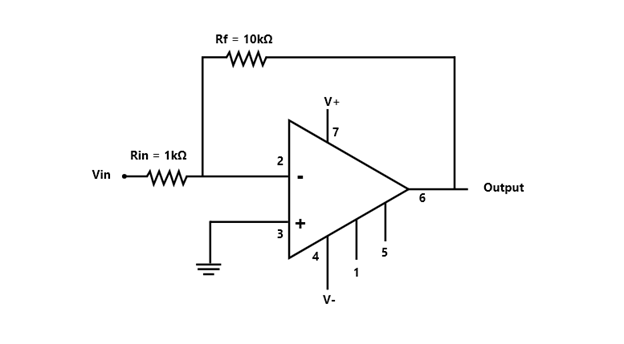
Op-Amp diagram
Before you start, you need to connect the LM741 to the circuit. To begin with, place the +15VDC to pin 7 and the -15VDC to pin 4. Make sure to do this so that the op-amp has a bias power to amplify.
Circuit Equations
Once the IC connects to the circuit, the voltage output is equal to:
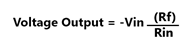
And the current gain of the op-amp inputs is also similar to:
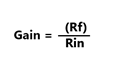
If you want to increase the op-amp's growth, you only have to use Rf's more considerable resistor value. However, if you're going to decrease the payment, you must use a lower resistance value for the Rf. Op-amp calculators go a long way in getting accurate values.
The Schematics
Here is the circuit diagram of the night light.
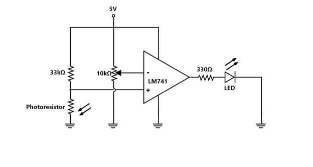
Night light complete amplifier circuit
In the diagram above, the op-amp is powered by 5 volts; this is the V+ terminal. Lastly, the V- input terminal connects to the ground. Therefore, these two inputs are inverting and noninverting. And finally, the voltage divider connects to the noninverting input.
For this reason, input voltages may vary depending on the level of ambient lighting. All this happens when you adjust the potentiometer. Subsequently, the change will demonstrate the voltage change.
Once the circuit calibration is complete, the experiment is ready to go.
The Experiment Breakdown
When in light, the photoresistor’s resistance is less than the set 33kΩ. As a result, the positive output voltage flows to the 33kΩ instead of the photoresistor. During this phase, the voltage from the non-inverting terminal is less than that on the inverting terminal. Consequently, the Light Emitting Diode does not switch on.
However, in no light or low lighting situations, the opposite happens. The potentiometer has more voltage resistance compared to the original 33kΩ.
Hence more voltage and alternating current will flow across it and not the 33kΩ resistor. For this, the non-inverting terminal’s voltage is more than that on the inverting terminal. As a result, the Light Emitting Diode will be turned on.
Application For Comparators
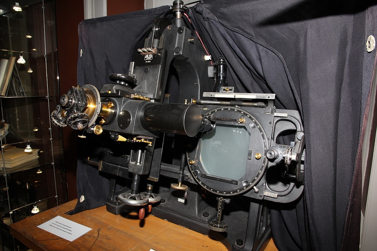
Blink Comparator 2
Source: Wikimedia Commons
- For smartphones
- Automotive application
- Astable multivibrators
- Heartbeat sensor
- Humidity monitoring system
- Light alarm
- Monostable multivibrators
- Oscillator
- Phase comparator
- Smoke alarm
- Temperature alarm
- Window comparator
Conclusion
In conclusion, with the knowledge above, you now have unlimited flexibility to experiment. Finally, if you want to broaden your knowledge of all things electronics, we got your back. Do not hesitate to contact us.
Special Offer: Get $100 off your order!
Email [email protected] to get started!