Want to learn how a circuit works, improve your knowledge of electronics, or just spend some time creating an interesting gadget? Try these easy transistor projects. Whether it’s your first or umpteenth circuit, these projects are ideal ways to build up or keep your skills sharp.
And if you need bare PCBs for your transistor projects, get in touch with OurPCB! Our low-volume PCB services are ideal for budding circuit builders and semi-pros alike.
Contents
- Understanding Transistors
- Types of Transistors
- Key Parameters and Specifications
- Why Engage in Transistor Projects?
- Learn the Fundamentals
- Hands-On Learning
- Test Innovative Ideas
- Essential Tools and Knowledge for Transistor Projects
- Identifying NPN vs. PNP Transistors
- Basic Tools
- Common Components
- PCB Design Software
- Simple Transistor Projects for Beginners
- 1. LED Blinker Circuit
- 2. Transistor as a Switch
- 3. Simple Transistor Amplifier
- Intermediate Transistor Projects
- 1. Automatic Night Light
- 2. Water Level Indicator
- 3. Rain Alarm
- 4. Temperature Sensor Circuit
- Advanced Transistor Projects
- 1. 7-Segment Counter
- 2. Automatic Volume Control Circuit
- 3. Transistor-Based Oscillator
- 4. Transistor H-Bridge Motor Driver
- PCB Design for Transistor Projects
- The PCB Design Process
- Optimising PCB Designs for Transistor Circuits
- Troubleshooting Common Issues
- Transistor Overheating
- Noise and Interference
Understanding Transistors
Transistors are fundamental components in modern electronics, acting as tiny switches or amplifiers. They are made from semiconductor materials, which can conduct electricity under certain conditions.
A transistor controls the current between two terminals, called the collector and the emitter. It exerts this control by applying a small voltage or current to a third terminal, known as the base.
The transistor acts as an amplifier by boosting the input signal, or as a switch by turning the current on and off. Transistors are found in nearly every electronic device.
Types of Transistors
Transistors come in several types, each with unique characteristics and uses:
Bipolar Junction Transistors (BJTs)
These traditional transistors have been used for decades. They have three layers of semiconductor material and come in two main types: negative-positive-negative (NPN) and positive-negative-positive (PNP). BJTs are known for their high current-carrying capacity and are used in applications that require amplification.
Field-Effect Transistors (FETs)
FETs control current by applying a voltage to an electric field. They come in two main types: Junction FETs (JFETs) and Metal-Oxide-Semiconductor FETs (MOSFETs). MOSFETs are especially popular in digital circuits because they have a high switching speed. FETs are widely used in integrated circuits and microprocessors.
Insulated-Gate Bipolar Transistors (IGBTs)
IGBTs combine the features of BJTs and MOSFETs, making them suitable for high-power applications. They are commonly used in power electronics, like motor drives, inverters, and electric vehicles, because they can handle large voltages and currents.
Key Parameters and Specifications
Understanding the key parameters and specifications of transistors will help you choose the right type for your application.
- Current Gain (β): Current Gain measures the transistor’s ability to amplify current. It’s the ratio of the output current (collector current) to the input current (base current) in a BJT.
- Threshold Voltage (Vth): Threshold Voltage is the minimum voltage required to turn on an FET. For MOSFETs, this affects the device’s switching characteristics and power consumption.
- Maximum Collector-Emitter Voltage (Vce): This is the maximum voltage that can be applied across the collector and emitter of a BJT without causing breakdown.
- Maximum Drain-Source Voltage (Vds): For FETs, this parameter indicates the highest voltage that can be applied between the drain and source terminals without causing breakdown.
- Power Dissipation (Pmax): Power dissipation specifies the maximum amount of power the transistor can dissipate without overheating. It helps prevent thermal damage in high-power applications.
- Switching Speed: Switching speed refers to how quickly a transistor can turn on and off. Faster switching speeds are essential for high-frequency applications and digital circuits.
Why Engage in Transistor Projects?
Engaging in transistor projects is a valuable activity for both beginners and experienced electronics enthusiasts. Transistors are the building blocks of modern electronic devices. Moreover, working on simple projects using transistors can deepen your understanding of how they function.
Learn the Fundamentals
Transistor projects are ideal for learning the basics of electronics. They introduce key concepts such as current, voltage, and resistance, as well as help you become familiar with reading circuit diagrams and using essential tools like multimeters and oscilloscopes.
Hands-On Learning
Hands-on learning is one of the most effective ways to grasp complex subjects. By physically building and testing circuits, you can see firsthand how theoretical concepts apply in real-world situations.
Test Innovative Ideas
Transistor projects are excellent for testing new ideas and innovations. Whether you’re developing a new type of amplifier, designing a custom switch, or creating a simple signal generator, transistors can be at the heart of your invention.
Essential Tools and Knowledge for Transistor Projects
Identifying NPN vs. PNP Transistors
NPN transistors are ideal for low-power applications because they have a higher current-carrying capacity. In contrast, PNP transistors are ideal for high-speed applications because they have a lower turn-on voltage.
To identify them, you can use a multimeter. Set the multimeter to diode test mode and place the positive lead on the base. If there’s a voltage drop when you touch the negative lead to the collector or emitter, it’s an NPN transistor.
For a PNP transistor, the process is reversed: place the negative lead on the base and the positive lead on the collector or emitter to check the voltage drop. Knowing the difference between these two types of transistors is important for proper circuit design and functionality.
Basic Tools
For any transistor project, you’ll need some basic tools:
- A soldering iron and solder for making electrical connections
- A multimeter is a must for measuring voltage, current, and resistance, and for testing
- Breadboards are useful for prototyping circuits without soldering
- Wire cutters and strippers for preparing wires
- Needle-nose pliers for bending and positioning components
- A good set of screwdrivers, tweezers, and a magnifying glass can also be very helpful
Common Components
Aside from transistors, you’ll need resistors, capacitors, and diodes. These are fundamental for shaping signals and providing the right conditions for transistors to operate.
Integrated circuits (ICs) can help simplify complex designs by integrating multiple functions into a single chip. LEDs indicate power or activity in a circuit. You may also need connectors, switches, and batteries.
PCB Design Software
Designing printed circuit boards (PCBs) is easier with good software. Using one of these tools, you can create precise and organized layouts to enhance your projects.
- EasyEDA is a user-friendly, web-based tool that integrates schematic capture and PCB layout.
- KiCad is a free, open-source option that offers advanced features for more complex designs.
- Altium Designer provides a comprehensive suite of tools for PCB design but comes with a higher price tag. This software is typically used in professional contexts.
Special Offer: Get $100 off your order!
Email [email protected] to get started!
Simple Transistor Projects for Beginners
These basic transistor circuits for beginners are the perfect way to get started with electronics. They are simple but fun, and provide an excellent hands-on way to understand the fundamentals.
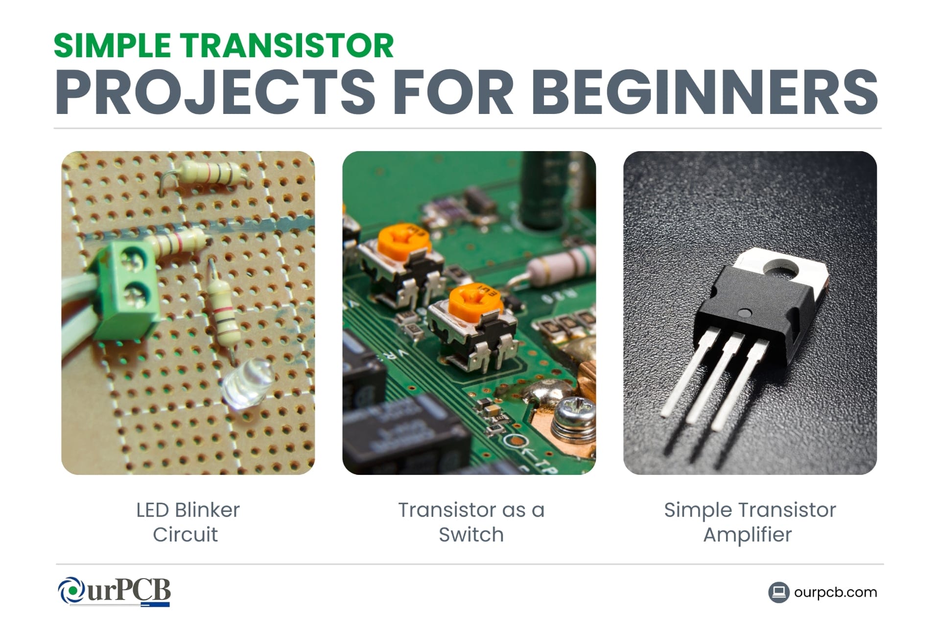
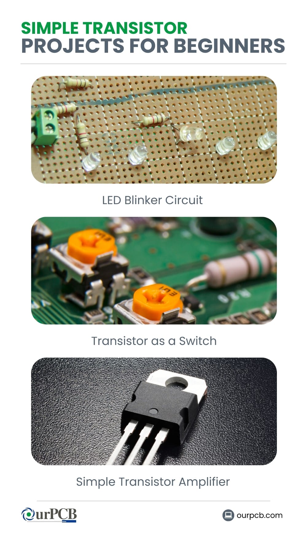
1. LED Blinker Circuit
An LED blinker circuit is a great starting point for newbies. It involves a simple setup where a transistor is used to switch an LED on and off. The blinking effect is achieved by using capacitors that charge and discharge, turning the transistor on and off in the process.
To build this circuit, you’ll need:
- A 2N2222 NPN transistor
- Resistors (220Ω and 1kΩ)
- Capacitors (10µF electrolytic)
- An LED
- A breadboard and jumper wires
- A power supply (3 to 9V)
The setup involves connecting the transistor, LED, resistors, and capacitors on a breadboard. When powered, the LED will blink, showing how transistors can control current flow.
2. Transistor as a Switch
Using a transistor as a switch is one of the simplest electronics projects for beginners. This helps you understand how transistors can be used to control larger currents with a small input signal.
For this project, you’ll need:
- An NPN transistor (e.g., 2N2222 or BC547 transistor)
- A DC motor or LED
- A diode (to protect against back EMF if using a motor)
- Resistors
- A breadboard and jumper wires
- A power supply
In this setup, the base of the transistor is connected to a control signal. When this signal is applied, the transistor allows current to flow from the collector to the emitter, powering the motor or LED.
3. Simple Transistor Amplifier
A simple transistor amplifier project introduces you to amplifying weak signals. This circuit can amplify audio signals or any small electrical signal, making it louder or more noticeable.
To build a simple transistor amplifier, gather the following components:
- A transistor (e.g., BC547)
- Capacitors (electrolytic, 10µF, and 100µF)
- Resistors (1kΩ, 10kΩ)
- A speaker or headphones
- A breadboard and jumper wires
- A power supply
In this circuit, the transistor amplifies the input signal applied to its base. The amplified signal is then output through the collector to drive a speaker.
Intermediate Transistor Projects
Intermediate transistor projects are perfect for hobbyists looking to expand their skills in electronics. Try one (or more) of these to boost your practical knowledge.
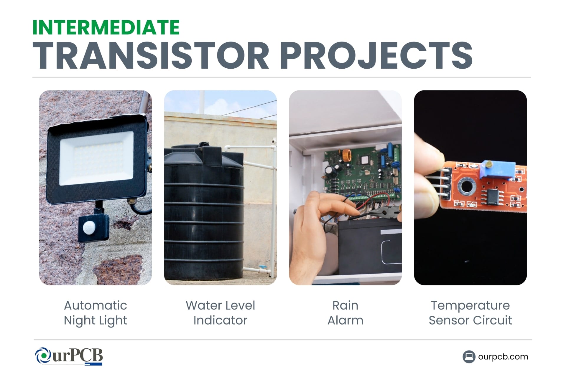
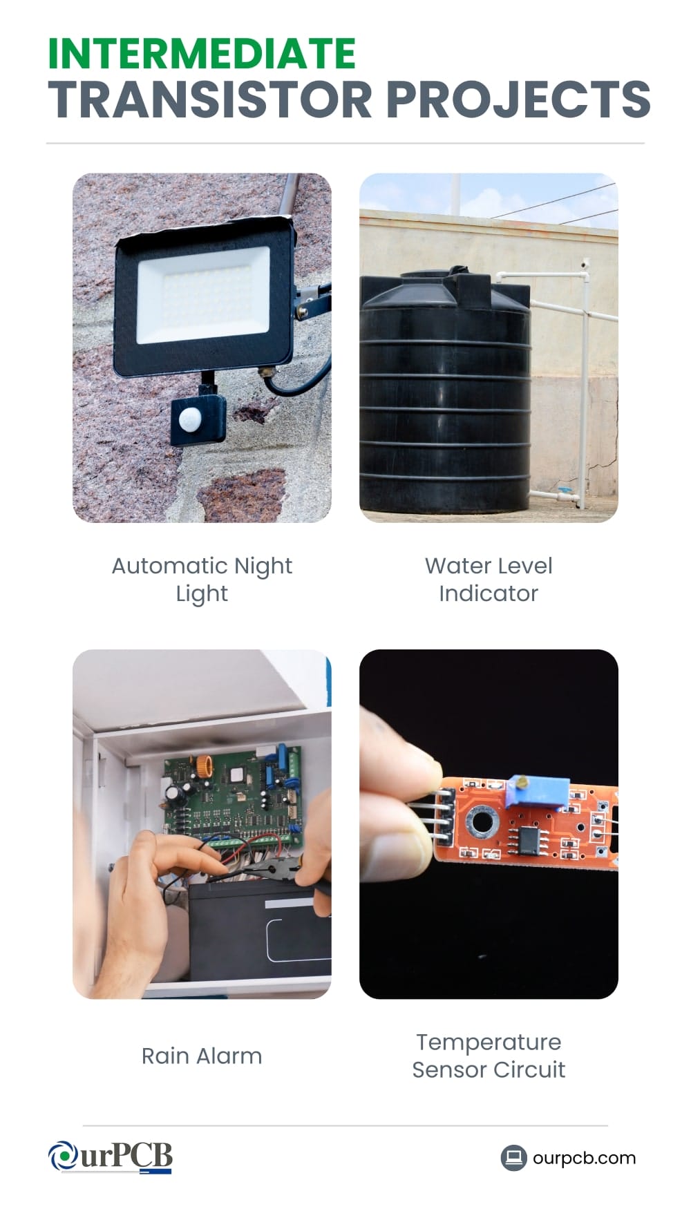
1. Automatic Night Light
An automatic night light circuit uses a transistor to turn on a light when it gets dark. It’s more than just a fun project — it’s also practical!
For this project, you’ll need:
- Light Dependent Resistor (LDR)
- NPN transistor (e.g., BC547)
- Resistors (100Ω, 47kΩ, 1kΩ)
- LED
- A power source
Connect the LDR and a resistor in a voltage divider configuration to the base of the transistor. The emitter goes to ground, and the collector is connected to the LED and the positive terminal of the power supply.
The LDR detects light levels. During the day, when there’s plenty of light, the resistance of the LDR is low, keeping the transistor off, and the LED remains off. At night, the LDR’s resistance increases, which allows current to flow through the transistor and lights the LED.
2. Water Level Indicator
A water level indicator circuit helps monitor the water level in a tank and alerts you when it reaches a certain level. This can also be very helpful for use around the house.
For this project, you’ll need:
- NPN transistors (like BC547)
- Resistors
- LEDs
- Wires
- Probes
Place the probes at different levels in the tank. Connect each probe to the base of a transistor through a resistor. The emitters go to ground, and the collectors are connected to LEDs and a power source.
When the water reaches the level of the probes, it completes the circuit, allowing current to flow through the transistor and lighting up the corresponding LED.
3. Rain Alarm
A rain alarm circuit alerts you when it starts raining. For this project, you’ll need:
- Transistors (e.g., BC547)
- Resistors
- LED
- Buzzer
- Power supply
- Water sensor
Connect the rain sensor to the base of the transistor through a resistor. The emitter goes to ground, and the collector is connected to the buzzer and the positive terminal of the power source. When rain hits the sensor, it lowers the resistance, which lets current to flow through the transistor and activates the buzzer.
4. Temperature Sensor Circuit
A temperature sensor circuit can be used to monitor temperature changes in an environment. Pair it with the rain sensor for a weather monitoring machine!
- Thermistor
- NPN transistor
- Resistors
- LED or buzzer
- A power source
Connect the thermistor and a resistor in a voltage divider configuration to the base of the transistor. The emitter goes to ground, and the collector is connected to the LED or buzzer and the positive terminal of the power source.
The thermistor changes its resistance with temperature. As the temperature increases, the resistance decreases, allowing more current to flow through the transistor, which can then trigger an LED or buzzer.
Advanced Transistor Projects
Once you’re past the level of creating simple circuits with transistors, try these more advanced transistor projects.
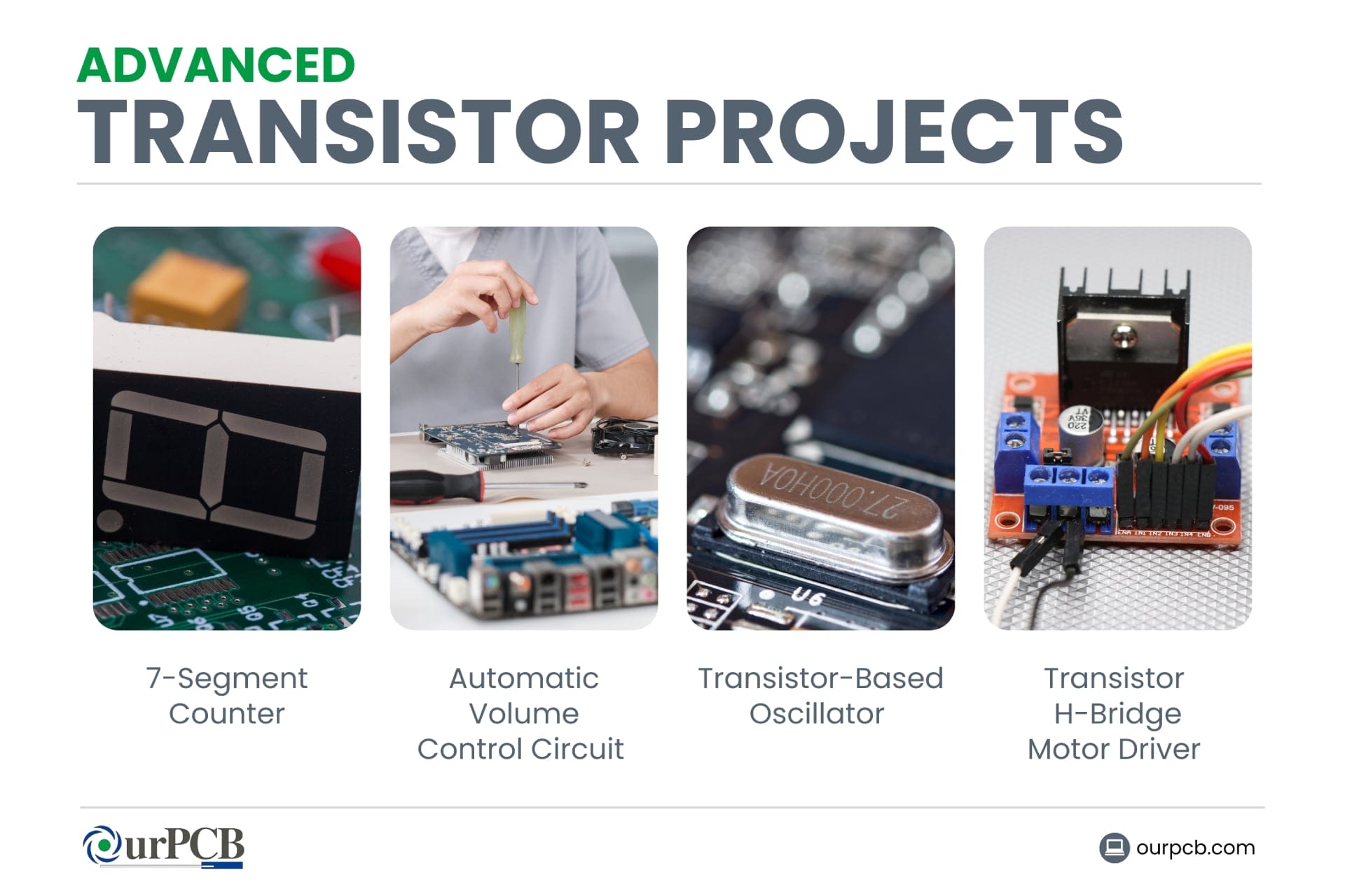
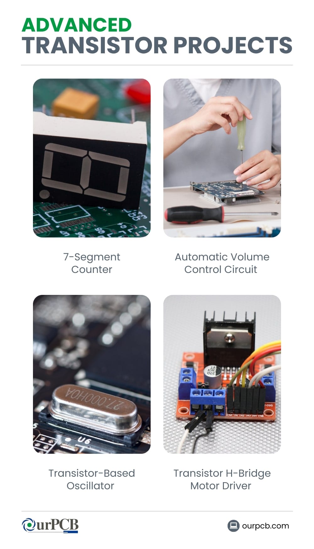
1. 7-Segment Counter
A 7-segment counter is a common project that displays numbers on a 7-segment display using transistors and an IC. The circuit can count from 0 to 9 and reset back to 0. This is perfect for digital counters, timers, and scoreboards.
To build this project, you’ll need:
- A 7-segment display
- Resistors
- Capacitors
- Push-button switches
- A power supply
This project typically uses a CD4026 decade counter IC and an NE555 timer IC. The NE555 timer generates clock pulses which are fed into the CD4026, incrementing the display with each pulse.
2. Automatic Volume Control Circuit
An automatic volume control circuit will maintain a constant audio output level by adjusting the volume based on the input signal’s strength. These simple transistor circuits are useful in audio applications where consistent output volume is needed, like public address systems or home audio systems.
To build this project, you’ll need:
- Transistor
- Capacitors
- Resistors
- Diode
- Power supply
This project involves using a transistor as a variable resistor controlled by the audio signal. Typically, an op-amp like the LM358 is used to sense the audio signal level and adjust the base current of the transistor, controlling the volume.
3. Transistor-Based Oscillator
A transistor-based oscillator generates a periodic waveform, which can be used in various applications like signal generators, clocks, and audio devices. One common type is the astable multivibrator, which creates a square wave output. To create one, you’ll need:
- Two transistors
- Resistors
- Capacitors
The transistors switch on and off alternately, charging and discharging the capacitors, which determines the frequency of the oscillation. This project is great for learning about feedback and time constants in electronic circuits.
4. Transistor H-Bridge Motor Driver
A transistor H-Bridge motor driver allows you to control the direction and speed of a DC motor. This circuit uses four transistors arranged in an H-shape, with the motor connected in the center.
By switching the transistors on and off in different combinations, you can control the direction of the motor’s rotation. By using PWM (Pulse Width Modulation) signals, you can control the motor’s speed. This project is ideal for robotics and automation applications where precise motor control is required.
PCB Design for Transistor Projects
PCBs provide a compact and organized way to connect various electronic components. For transistor projects, PCB design helps you make sure your circuit performs optimally by minimizing noise and maximizing stability.
The PCB Design Process
Schematic Design
The first step in PCB design is creating a schematic — a detailed circuit diagram that shows how each component is connected. It’s important to correctly identify the pin configurations. Software like KiCad allows you to create and verify schematics.
Layout Design
This step involves placing the components on the PCB and routing the traces that connect them. Key considerations include minimizing trace lengths to reduce resistance and inductance, and placing decoupling capacitors close to power pins to filter out noise.
Prototype Testing
The next step is fabrication and testing. You can use services like OurPCB to manufacture your bare boards. Once you receive the PCBs, solder the components and test the circuit.
Optimising PCB Designs for Transistor Circuits
To optimize your PCB design for transistor circuits, consider the following tips:
- Thermal Management: Use heat sinks or thermal vias for proper heat dissipation
- Signal Integrity: Use ground planes and proper trace routing to minimize noise and interference
- Component Placement: Position transistors and associated components to minimize trace lengths and reduce parasitic inductance and capacitance
- Power Distribution: Use wide traces for power and ground connections to handle the current requirements and reduce voltage drops
Troubleshooting Common Issues
Transistor Overheating
Transistors are key components in electronic circuits, but they can overheat due to excessive current, inadequate cooling, or improper installation. Regularly inspect and clean cooling systems to prevent dust buildup.
Make sure you have proper heat sinking and ventilation. Use thermal paste to improve heat transfer, and double-check that transistors are operating within their rated limits.
Noise and Interference
Electrical noise and interference can disrupt the operation of electronic devices, causing malfunctions. This may be caused by electromagnetic interference (EMI) from other devices, poor shielding, or grounding issues.
Use shielded cables and enclosures to reduce EMI. Make sure you’ve got proper grounding and maintain separation between power and signal cables. Installing filters or surge protectors can also help mitigate interference.
Back to Top: Transistor Projects | Simple Transistor Circuits & DIY Transistors
Special Offer: Get $100 off your order!
Email [email protected] to get started!