Detecting and measuring temperature changes is critical for several applications. Electronic circuit protection is also vital for safeguarding PCB elements. What do these two have in common? The device used for these functions is usually a PTC thermistor. This tiny device is very versatile, and we have covered it in detail below. Take a look!
Contents
- What are PTC Thermistors?
- PTC Thermistor Symbol
- Working Principle of PTC Thermistor
- Types of PTC Thermistors
- Sister Silicon PTC Thermistor
- Ceramic Switching PTC Thermistor
- Polymeric PTC (PPTC) Thermistor
- Characteristics of PTC Thermistors
- Transition Temperature (Tc)
- Minimum Resistance (Rmin)
- Rated Resistance (R25)
- Dissipation Constant
- Maximum Rated Current
- Maximum Rated Voltage
- Modes of Operation
- Self-Heated Mode
- Sensing (Zero-Power) Mode
- PTC Thermistor Vs. PTC Fuse
- NTC vs. PTC Thermistors
- Advantages and Disadvantages of PTC Thermistors
- Advantages
- Disadvantages
- Typical Applications for PTC Thermistors
- Summary
What are PTC Thermistors?
Compared to ordinary resistors, PTC thermistors are temperature-sensitive resistors. The word thermistor is a combination of two words: thermal and resistor.
On the other hand, PTC is an abbreviation for positive temperature coefficient. This property forms the main working principle of a PTC thermistor. It means the resistance of a PTC thermistor increases at higher temperatures.
PTC Thermistor Symbol
If you study circuit diagrams containing a PTC thermistor, its symbol includes the +t° character to indicate a positive temperature coefficient. This character differentiates this thermistor from other types, such as the NTC ( negative temperature coefficient) thermistor.
Working Principle of PTC Thermistor
The core working principle of a PTC thermistor depends on temperature changes affecting the resistance. Both properties (absolute temperature and internal resistance) are directly proportional. Therefore, the thermistor self-heats when current flows through, and this increase in temperature causes a resistance increase.
Polymer PTCs contain a slice of plastic with carbon grains embedded in them. However, most PTC thermistors have ferroelectric materials like BaTiO3 (barium titanate), whose dielectric constant changes with temperature. But at a specific critical temperature, the material's resistance increases suddenly.
Also worth mentioning is the Steinhart-Hart equation for any given PTC Thermistor. It calculates the resistance of a thermistor with greater precision as a function of temperature. The narrower the range of temperatures, the more accurate the resistance calculation. Most thermistor manufacturers provide the A, B, and C Steinhart-Hart coefficients for a typical operating temperature range.
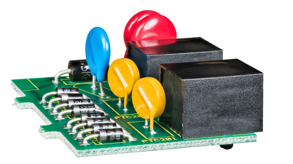
Colored thermistors on green circuit board
Types of PTC Thermistors
The following are the three types of thermistors.
Sister Silicon PTC Thermistor
This sensitive silicon resistor exhibits a linear relationship between resistance and temperature, showing significant PTC resistance. However, the linearity changes after 150°C and above because the thermistor begins showing an NTC (Negative Temperature Coefficient). Therefore, the thermistor’s application primarily uses temperature sensors and temperature compensation.
Ceramic Switching PTC Thermistor
This type of thermistor has a highly non-linear response curve. Raising the temperature initially decreases the resistance until it reaches a fixed temperature level. Above that level, resistance increases drastically. Thermistor applications for these properties include PTC self-controlled heaters, sensors, temperature compensation, etc.
Polymeric PTC (PPTC) Thermistor
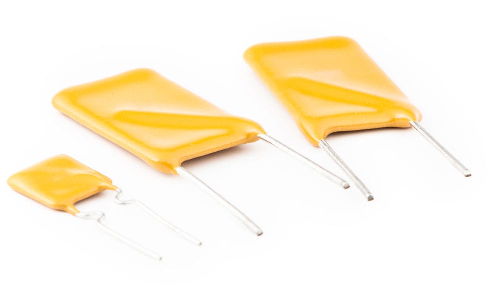
A resettable fuse
Also known as a resettable fuse, a PPTC-type thermistor exhibits a non-linear R-T curve. The thermally activated device reacts to ambient temperature changes, which affects its performance. But PPTC units have lower resistance in normal operating conditions than other circuit elements. Therefore, they have less circuit control.
However, when there is a fault in the circuit configuration, the component responds by going into a tripping condition. The PPTC resets itself to regular operation only when the error gets eliminated. Therefore, the thermistor in question is one of the ideal devices for circuit protection.
Special Offer: Get $100 off your order!
Email [email protected] to get started!
Characteristics of PTC Thermistors
From the R-T curve, we can derive the following PTC thermistor characteristics.
Transition Temperature (Tc)
Tc is also known as the switch or Curie temperature. The temperature at which the resistance of a switching type PTC thermistor begins to rise rapidly.
But before reaching this point, PTC thermistors exhibit a negative temperature coefficient up to the minimum resistance point. However, after hitting the minimum resistance, the resistance increases as the temperature rises.
Minimum Resistance (Rmin)
The minimum resistance is the point on the resistance vs. temperature curve at which the temperature coefficient turns positive. Also, it is the lowest measurable resistance on a switched type PTC thermistor.
Rated Resistance (R25)
The rated resistance is a classification metric used to rank thermistors by their resistance value. You measure it by passing a low enough current through the thermistor that does not cause self-heating, affecting the measurement. Usually, the PTC rated resistance is the resistance at 25°C.
Dissipation Constant
This constant is the relationship between applied power and the resulting increase in body temperature caused by self-heating. It has a significant impact on the self-healing properties of the PTC. Factors like the thermistor mounting, contact wire materials, ambient temperature, and convection/conductive path affect the dissipation constant.
Maximum Rated Current
Maximum rated current is the highest current that can flow through a PTC thermistor constantly at specified ambient conditions. Therefore, exceeding this current to the point where the temperature coefficient lowers will result in a runaway power situation. This situation will destroy the thermistor.
Maximum Rated Voltage
The max-rated voltage is the highest voltage that the thermistor can handle continuously at specified ambient conditions. However, this voltage value depends on the dissipation constant and the thermistor's resistance vs. temperature curve.
Modes of Operation
PTC thermistors have the following modes of operation that depend on the application.
Self-Heated Mode
In this mode of operation, a voltage applied to a thermistor allows sufficient current to flow through. This energy flow raises the thermistor's body temperature. Initially, the ferroelectric prevents the formation of a barrier between the crystal grains below the Curie temperature. This prevention leads to low resistance.
However, the resistance quickly rises when approaching the critical temperature because this breaks barriers at the grain boundaries. But the relationship between resistance and temperature is non-linear. A resistance change at the Curie temperature can be several orders of magnitude within a few degrees Celsius.
However, if the voltage is constant, the current flowing through will stabilize as the thermistor attains thermal equilibrium. This peak device temperature depends on the applied voltage and the dissipation factor. You can calculate it using the following equilibrium equation.

Sensing (Zero-Power) Mode
Here, the power consumption of the thermistor is tiny and has a negligible effect on the temperature. Consequently, it has little impact on the resistance.
It is possible to keep a constant temperature internally. Do this by keeping the current low to reduce the resistive heating effect of the thermistor. The body temperature will remain low, and only the surrounding temperature will affect the device.
This mode is ideal for ambient temperature sensing applications due to the low peak device temperature. Electrical heating might introduce errors and hamper the device's ability to give accurate temperature readings.
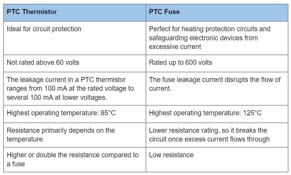
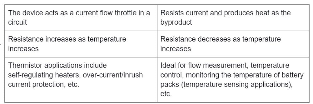
PTC Thermistor Vs. PTC Fuse
The following are the differences between a PTC Thermistor and PTC Fuse.
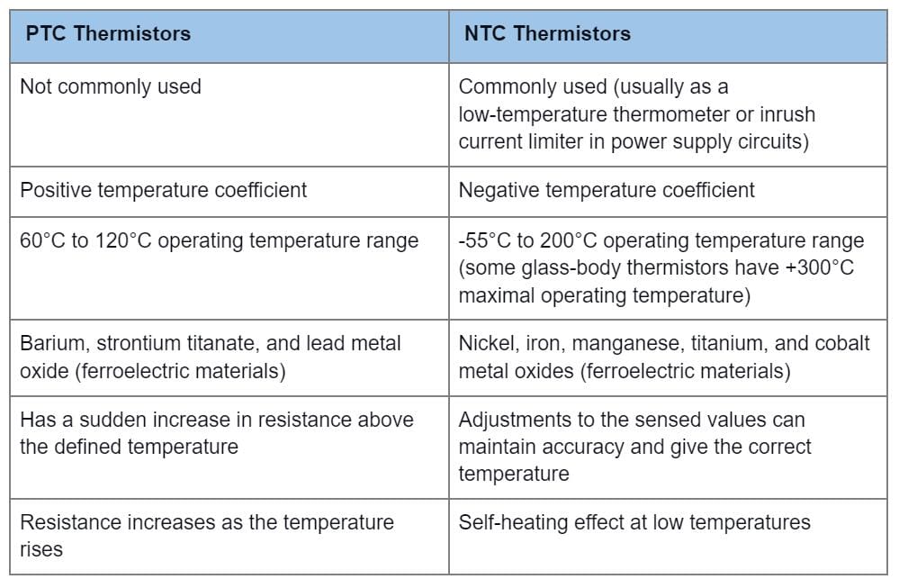
NTC vs. PTC Thermistors
NTC and PTC thermistors have the following differences.
Advantages and Disadvantages of PTC Thermistors
Advantages
- Less expensive than other temperature sensors
- Compact size (allows for their operation in places with limited space)
- Quick response
- Stable and powerful
- Requires no further calibration if it has the correct temperature curve (R-T curve)
Disadvantages
- Delicate
- Curved output
- The non-linear characteristics create problems when determining the correct temperature measurement.
- Not ideal for wide temperature range applications (limited temperature range)
- Non-linear at maximum temperatures (advisable to use them below 100°C or use a linearization resistor)
Typical Applications for PTC Thermistors
PTC thermistors have a wide range of applications, which include the following:
- Self-regulating heaters (temperature sensor)
- Over-current protection in electric motor windings, solenoids, etc.
- Time delay
- Electric motor starting (PTC thermistor motor sensor)
- Inrush current limiting power thermistors
- Medical equipment temperature control
- Liquid level sensing
- Replacements for fuses (resettable fuses)
- Thermal switch in electronic devices
Timers in CRT display degaussing circuits
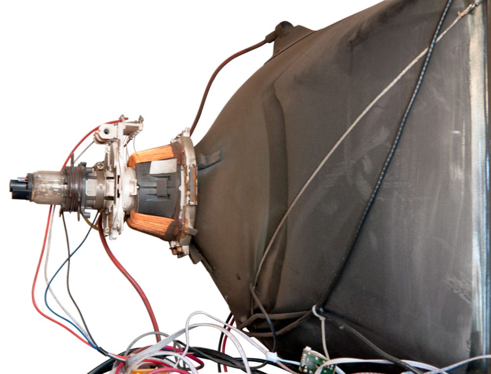
A CRT
Summary
In conclusion, PTC thermistors have many applications due to their sensor and self-heating modes. However, you may need to maintain a base resistance in electronic circuits or limit the current running through based on specific temperature response constraints. If you encounter any issues when incorporating this device into your project, contact us to get more details.
Special Offer: Get $100 off your order!
Email [email protected] to get started!