Do you have aging parents, relatives, or friends, or do you know someone with hearing loss?
Sensorineural hearing loss occurs regularly among aging persons, and a hearing aid user can spend over $1,000 to buy a hearing aid set.
Instead of spending all that money, we have an affordable solution.
Creating a hearing aid is a simple DIY project, especially if you are an electronics inventor.
Read on to learn how to make cheap & small hearing aid circuits and energy-efficient types using a few discrete components.
Contents
What is a Hearing Aid Circuit?
A hearing aid circuit is an arrangement of components that includes a microphone, amplifier, and earphone.
However, the courses vary in complexity because some have sound detection systems.
How Does a Hearing Aid Work?
Even though the circuits might differ, hearing aids have a similar working principle.
Sound comes in through the microphone, then gets magnified in the amplifier.
In most cases, the amplifier is a signal processor that determines how high or low to amplify the sound signal.
The component might also have low and high cut-off filters to eliminate input noise and alter the signal to improve the sound quality.
After this, the signal gets converted into sound via the earphone, then goes into the ear.
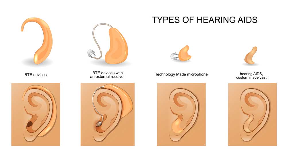
Types of hearing AIDS
Special Offer: Get $100 off your order!
Email [email protected] to get started!
Cheap & Small Hearing Aids Circuit Projects
To make a small and cheap hearing aid, you need these nine 0.25W, 5% tolerance resistors:
- Two 10K resistors
- One 1M resistor
- One 4.7K
- Two 100K
- One 1.5K
- One 3.9K
- One 100Ω
- A 50K (A) variable resistor (potentiometer)
Yow will also need seven capacitors that include:
- Two 0.1µF 50V ceramic capacitors
- One 470pF 50V ceramic capacitor
- Two 1µF 50V electrolytic capacitors
- A 10µF 25V electrolytic capacitor
- One 470µF 16V electrolytic capacitor
Semiconductors are the main components in the circuit, and you will need five of them. These include:
- Three 45V 100mA BC547 NPN transistors
- A 45V 800mA BC337 NPN transistor
- One 1N4148 diode
The final pieces are an On-Off switch, a 1.5-Volt battery, microphone, headphones, and a PCB.
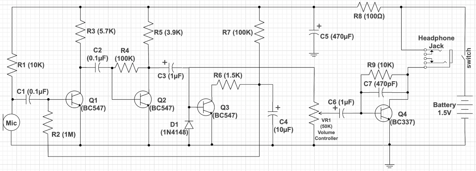
Cheap and small hearing aid circuit diagram
Preamplifier
The circuit begins operations at the battery, which powers the condenser microphone via R1 to get the sound input and convert it to an electrical signal.
Although the circuit uses DC from the battery power, capacitor C1 takes the mic signal and passes AC only to transistor Q1. This section acts as the first audio preamplifier.
C2 and Q2 form the second preamplifier, resulting in a high gain where R4 is the feedback, while R3 and R5 form the load.
Automatic Level Control
Next, the signal heads to the automatic sound level control section, where Q3 takes the bias current feedback to Q1 to control the amplifier volume.
Diode D1 acts as a filter to produce a stable signal voltage level, while C4 controls the step of volume control.
If the voltage value is high, the capacitor slows down the sound control and does the opposite if the value is low.
Therefore, if the mic captures louder signals in noisy environments, it causes a high bias current to Q3. The high wind causes a low voltage at the collector of Q3 and C4, resulting in a slowdown.
A weak signal causes a low-level volume control voltage and does the opposite.
The system enables normal hearing and is particularly useful when dealing with quiet sounds at conversational speech levels, which are harder to perceive for patients with severe hearing loss.
Headphone Power Amplifier
The signal then moves forward to the headphone amplifier section with VR1 for volume to match the degree of hearing loss.
Q4 is responsible for sound enhancement, while C7 assists with noise reduction and maintains the circuit’s stability by minimizing high-frequency range gain.
After this step, the signal goes to the headphone jack, which forms the load in the circuit and connects directly to the power supply.
Low-impedance headphones with a range of 16-32 ohms are the best for such a circuit because they require less voltage to drive them.
It is important to note that the setup will produce audible circuit noise levels when turning on and off due to the load past direct current.
Avoid listening during these periods because the internal noise is unhealthy for the ears and might damage headphones.
Headphone
Hearing Aid Circuit using 555
There is one problem with the circuit explained above. It consumes energy consistently after switching on, resulting in short battery life.
However, you can improve the hearing aid technology by adding a sound detection system using the NE555 integrated circuit timer.
You will also need an LM324 quad op-amp integrated circuit to complete the sound detection system.
Such a setup only powers on the amplifier section when it detects sound and consumes less power.
The other components you need include:
- Two BC549 NPN transistors
- A BC558 PNP transistor
- Two BC548 NPN Bipolar junction transistors
- Three 2.2kΩ resistors
- Two 3.3kΩ resistors
- Two 680kΩ resistors
- A 1MΩ variable resistor (Preset)
- 49kΩ, 220kΩ, 100kΩ, and 1.5kΩ resistors
- Two 0.1 µF ceramic disc capacitors
- A 0.01 µF ceramic disc capacitor
- 100 µF/25V, 470 µF/25V, and 1 µF/25V electrolytic capacitors
- Condenser microphone
- Earphone
- 9V battery
- On/off switch
- PCB
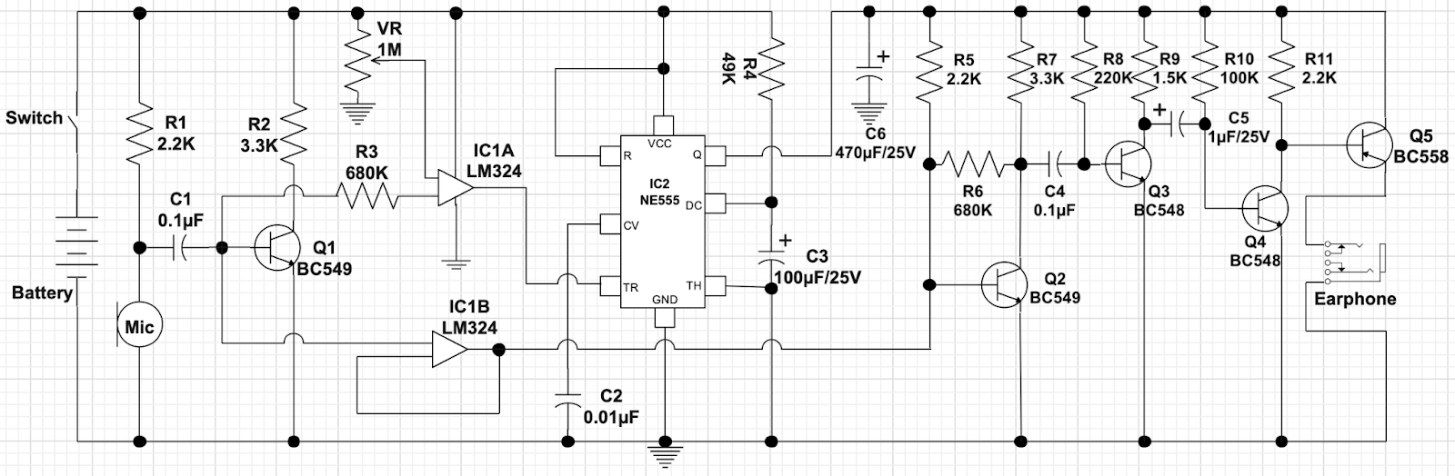
Smart hearing aid circuit diagram with a NE555 IC
How It Works
The circuit has a similar working principle to the small setup described above but adds on the LM324 (IC1A & IC1B) and NE555 timer. IC1A is the comparator, while IC1B is the unity follower.
Sound signals get converted into electrical signals in the microphone; then, the current is through to the preamplifier around Q1. The output of this process goes into the inverting pin of IC1A (pin two).
Since IC1A is a comparator, it compares this incoming signal with the available reference voltage at pin three (non-inverting pin).
If the voltage at the collector of Q1 is higher than the reference voltage, the comparator produces a low output that can trigger the NE555 timer.
However, if the reverse happens, IC1A outputs a high signal that powers the amplifier section.
IC1B also gets its input signal from the mic (non-inverting pin), while its inverting pin connects to its output to overcome the issue of impedance mismatch.
This output also flows into the base of transistor Q2 for amplification, then onto the last three transistors for further amplification. Unlike the other transistors, Q5 is a PNP type that aims to run the headphone.
Efficiency
In the figures, this circuit only consumes 6 mA when there is no sound to trigger the amplifier, but consumption rises to 96 mA with the amplifier working.
That is 90 mA less, making the hearing aid super-efficient.
Most hearing aids still use non-rechargeable zinc-air batteries, so high efficiency lengthens the period between replacements.
Apart from reduced power consumption, the circuit also allows you to adjust sensitivity and select the amplifier’s time on period.
Applications of Hearing Aid Circuits
- BTE (Behind the Ear) hearing aid
- ITE (In-The-Ear) hearing aid
- ITC (In the Canal) hearing aid
- CIC (Completely in the Canal) hearing aid
Summary
As you can see, hearing aids are not as complex as you might imagine, but the products are costly from most major hearing aid manufacturers.
Therefore, making one for your loved ones or your project is the best and cheapest alternative.
Also, you can enhance the circuit by incorporating components for digital signal processing and wireless technologies.
If you need the discrete components to make this DIY hearing aid circuit, or you want a complete PCB assembly, contact us for more details.
Special Offer: Get $100 off your order!
Email [email protected] to get started!