Oscillators are devices that convert a supply voltage, i.e., DC input, into a waveform, the AC output.
Often, you will find the output waveform in different frequencies and shapes, such as triangular, square, or sawtooth.
Further, the waveform shapes can be complex or just a simple sine wave, depending on the application area.
In this article, we will focus on an LC oscillator, which is a type of oscillator. It is also known as an LC-tuned circuit or an LC resonant circuit.
In addition, the article gives an overview of further divisions of the LC oscillators alongside the circuit working.
Contents
- What is an LC Oscillator?
- Principles of LC Oscillators/How Does an LC Circuit Work?
- Resonance Frequency Formula
- Types of LC Oscillators
- Tuned Collector Oscillator
- Tuned Base Oscillator
- Hartley Oscillator
- Colpitts Oscillator
- Clapp Oscillator
- LC Oscillator Application circuit
- LC oscillator with Crystal
- General Colpitts oscillators
- Simple LC RF Oscillator
- Difference between LC and RC Oscillator
- Application Areas of LC Oscillator
- Advantages and Disadvantages of LC Oscillators
- Advantages
- Disadvantages
- What Is the Difference Between an Amplifier and an Oscillator?
- Conclusion
What is an LC Oscillator?
The term LC comes from the tank circuit with an inductor 'L' and a C capacitor.
An LC Oscillator is an oscillator type whereby you use an inductor-capacitor (LC) tank circuit to give positive feedback.
The feedback is important in maintaining a stable oscillation.
You can almost always comprehend an LC oscillator using an active device like Op-Amps, BJT, MOSFETs, or FET.
Other times, they can generate high-frequency signals, hence making them RF oscillators.
Additionally, they apply to a wide range of electronic devices, such as tuner capacitors and RF signal generators.
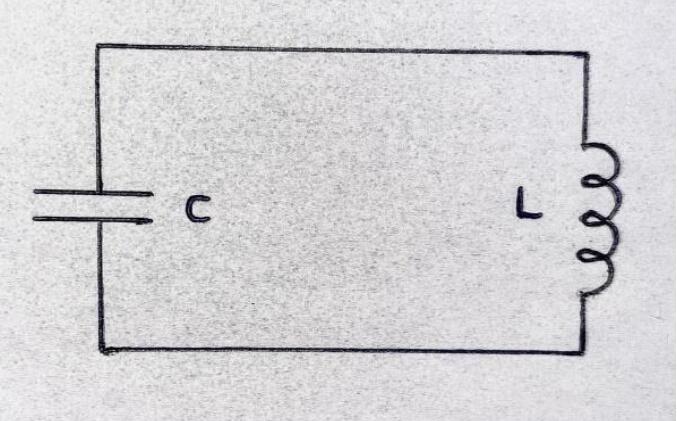
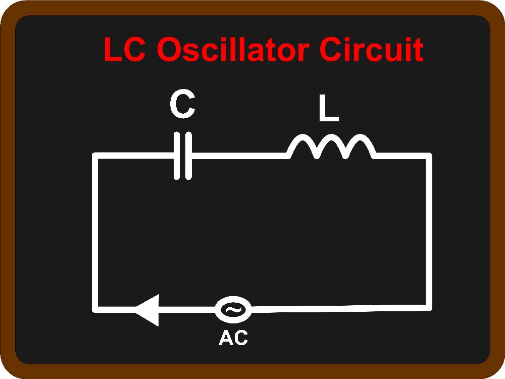
LC oscillator circuit
Principles of LC Oscillators/How Does an LC Circuit Work?
LC oscillators reverse the voltage polarity using an inductor (L) and a capacitor (C) to create the oscillating effect. And this oscillating effect will still occur whether you connect these devices in series or parallel.
Here’s how the circuit works. When you apply a voltage to the LC oscillator, the power source recharges the capacitor while the current flows through the inductor in one direction, forming a magnetic field.
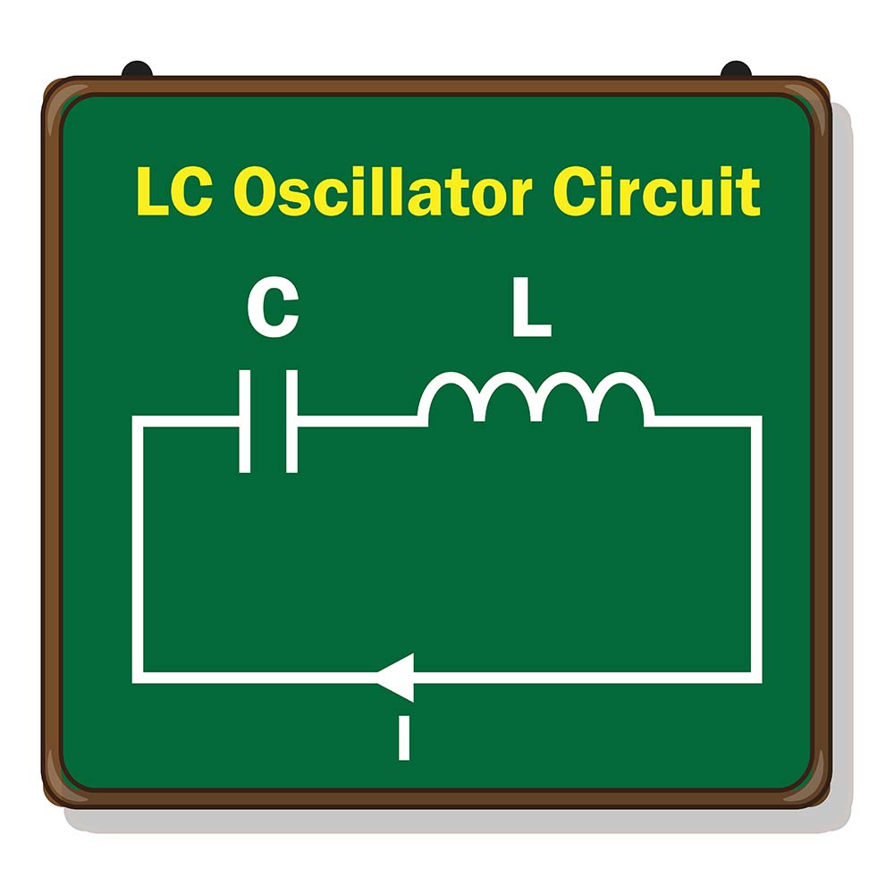
An LC oscillator circuit diagram
But when you disconnect the supply voltage, the capacitor feeds the stored charge to the inductor in reverse, which forms a magnetic field around it in the opposite direction.
As the voltage across the capacitor terminals drops to zero, the energy stored on the inductor’s magnetic field induces a voltage across this component because inductors oppose electric current changes.
This induced current recharges the capacitor but with an opposite polarity voltage to the immediate supply voltage.
When the magnetic field dissipates, the recharged capacitor will push the current back to the inductor in the opposite direction.
This back-and-forth flow of charge causes oscillations that generate AC waveforms at a particular frequency.
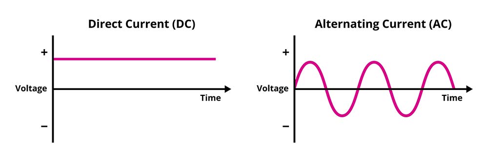
DC vs. AC waveform (voltage against time)
Resonance Frequency Formula
The tank or LC circuit only produces the oscillation frequency when under resonance, and you can calculate the resonant frequency using this formula.
IXLI = IXCI
2πfOL = 1/2πfOC
fO = 1/2π√(LC)
Where f is the frequency in Hertz, L is the inductance in Henry, and C is the capacitance in Farads.
An LC oscillator circuit diagram with an AC output
Types of LC Oscillators
-
Tuned Collector Oscillator
A tuned collector oscillator is the most basic LC oscillator. It has a capacitor and transformer with a parallel connection crossway to the oscillator's collector circuit.
Also, the capacitor and primary of the transformer form the tank circuit. Then, the secondary of the transformer gives a portion of oscillation feedback to the transistor's base.
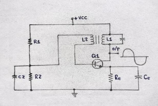
A tuned collector oscillator circuit
-
Tuned Base Oscillator
For the tuned base oscillator, you will find the tuned circuit between the ground and base of the transistor.
The capacitor and the transformer's primary coil form the tuned circuit. Then, the secondary coil of the transformer gives the feedback signal.
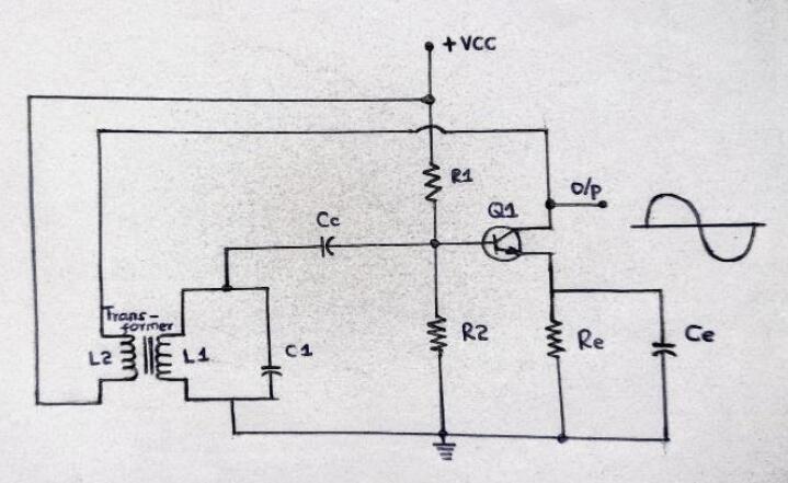
Tuned base oscillator circuit
-
Hartley Oscillator
Ralph Hartley invented the Hartley oscillator in 1915. For the tank circuit, he placed one capacitor and two inductors.
Further, the inductors have a series connection while the capacitor is parallel to the inductors' series combination.
Its operating oscillation frequency often ranges from 20KHz to 20MHz, and you can realize it using Op-Amps, FET, and BJT.
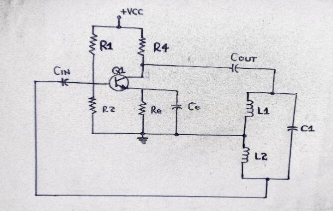
Hartley oscillator circuit
-
Colpitts Oscillator
The Colpitts oscillator is an LC oscillator invented by Scientist Edwin Colpitts in 1918. Its tank circuit comprises an inductor and two capacitors.
The capacitors have a series connection, whereas the inductor has a parallel connection to the capacitor series. Its operating range is approximately 20KHz to MHz.
And contrary to the Hartley oscillator, its frequency stability is better and reliable.
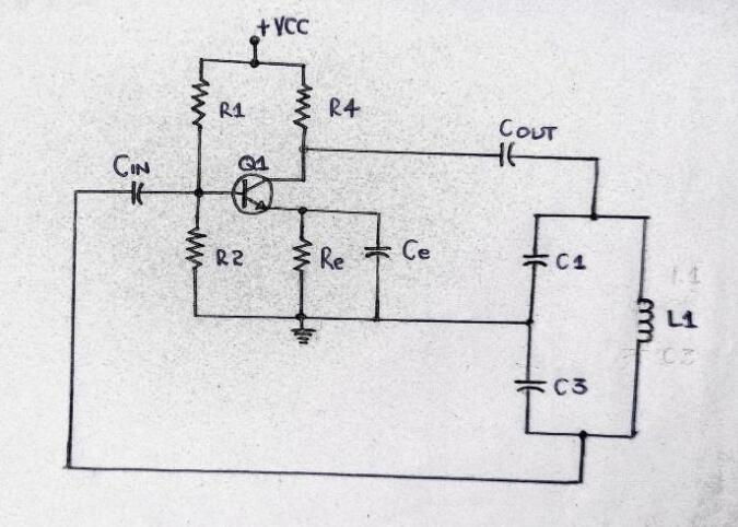
Colpitts oscillator circuit
-
Clapp Oscillator
We consider the Clapp oscillator as a modification of the Colpitts oscillator.
Thus, an additional capacitor in the tank circuit falls under the inductor series.
The added capacitor varies in variable frequency applications. It also isolates the two existing capacitors from transistor parameter effects such as junction capacitance.
What’s more, the extra capacitor heightens frequency stability.
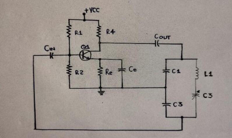
A Clapp oscillator circuit
Special Offer: Get $100 off your order!
Email [email protected] to get started!
LC Oscillator Application circuit
-
LC oscillator with Crystal
Before proceeding to the mechanism of action, let's consider the circuit below.
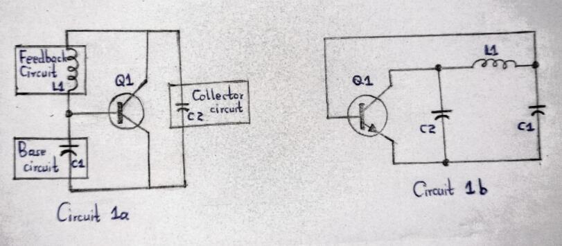
LC oscillator with crystal circuit
The large Q in the crystal oscillator minimizes the frequency drift that DC voltage fluctuations and the temperature have triggered.
Moreover, crystal-controlled oscillators produce less noise than traditional LC tank-based oscillator circuits, making them reliable in output signals.
In circuit 1a, three feedback circuits are configured with an NPN BJT-based amplifier.
Circuit 1 uses C2, C1, and L1 to make a comparative circuit.
Note: The two crystal oscillator circuits above use a minimum of an inductor and two capacitors. The crystal is an element of the feedback circuit.
- C2 and C1 comprise junction capacitance and residual transistor. Besides, C2 is analogous to a parallel network of a capacitor and an inductor.
- Then, the C2 and C1 pair is the third overtone selector of the crystal. This is because it shows a capacitive nature, mainly at the overtone frequency of the crystal. Also, it exhibits inductive properties at the crystal’s fundamental frequency.
- Thus, the C2 inductor hinders the crystal's fundamental frequency of oscillations.
- An oscillator circuit requires a limiting factor, a boundary at the oscillator’s output. The limiting factor complements its feedback and amplification. Majorly, the limitation should occur when the input signal rise doesn’t cause an output signal rise.
- The Colpitts crystal-controlled oscillator has tuning specifications and stringent load. Conversely, the pair of semi-isolated models require less input and are better for general-purpose applications.
- Regarding preferences in LC oscillator working, a Pierce crystal oscillator often gives an accurate output frequency. A Butler circuit, on the other hand, oscillates without a crystal.
-
General Colpitts oscillators
Colpitts oscillator circuit
We have two variations of the Colpitts crystal-controlled oscillator, i.e., the semi-isolated and standard variations.
Also, specifications of the load and crystal resistance determine the classic circuit.
In addition, the output power has less than 50 % restriction of the crystal's power dissipation but is still efficient.
- R3, R2, and R1 offer transistor Q1 the DC bias.
- Potentiometer R2 yields approximately 1.5 mA of the emitter current.
- C6, C4, and C3 function as bypass elements for the RF at the working frequency of XTAL1.
- C2 is the feedback base circuit.
- C5 and L1 display a net capacitive reactance when the circuit is operating at the operating frequency of XTAL1. Thus, they function as the collector circuit feedback capacitor.
- If you use overtone crystals, C5 and L1 act like an overtone selector, preventing oscillation at the crystal's fundamental frequency.
- C1, the adjustable trimmer, often tweaks L1 (the feedback component). The oscillator's output frequency will increase while the C1 value decreases.
-
Simple LC RF Oscillator
You can build an oscillator with a capacitor network, transistor, and resistor. And so, as you proceed, you'll only use the collector and emitter while leaving the transistor base terminal unconnected.
The simple LC oscillator circuit figure below often works at approximately 100kHz to 50MHz or sometimes higher.
LC RF oscillator circuit
- Transistor TR1 has a source follower configuration.
- Then, the tiny coupling through the T1 inductor winding generates a +ve feedback. Also, it can step up the voltage needed for oscillation maintenance.
- C3 and T1 primary winding form the LC-tuned circuit. As a result, the LC oscillator circuit operating frequency is established.
- At the supplied Direct Current, R1 is the source load for TR1. AC via C2 bypasses the TR1, leading to the T1 coupling winding that forms the TR1 source load.
- Afterward, you can derive the oscillator output signal through the TR1 source via C1, the DC blocking capacitor.
- C4 is the supply decoupling capacitor.
- If you need to adjust the tuning oscillator, you can replace C3 with a variable capacitor. Alternatively, use a mixture of variable and fixed capacitors to allow the wanted tuning range.
- Moreover, you can incorporate ready-made coils when constructing high and medium-frequency LC oscillators. Often, they'll provide more accurate frequency outputs compared to the home-wound waves.
- When constructing T1 as a DIY project, wind two sets of coils, 6 to 1 and 8 to 9. One set should be below the other around a small ferrite rod. You can also experiment with the number of turns to get varied frequency outputs.
NOTE: you should correctly connect the phasing of the smaller coupling winding. If you don't, your circuit won't oscillate. Thus, it calls for a trial-and-error implementation throughout the project.
Difference between LC and RC Oscillator
The main differences between RC oscillators and LC oscillators are as follows;
| LC Oscillator | RC Oscillator |
| First, they are appropriate at high frequencies. | They are applicable at low or medium frequencies. |
| Then, frequency stability is poor except for the clap oscillator. | The frequency stability is poor. |
| Further, oscillator frequencies depend on the R and C values. | Oscillation frequency depends on the L and C values. |
| Examples here include phase shift and Wein bridge. | Examples are the Armstrong oscillator, Hartley, clap, and Colpitts. |
| Application areas include medium and low-frequency signal generators. | Applications here are high-frequency sources such as radios and TVs and frequency synthesizers. |
Application Areas of LC Oscillator
The wide range of applications of LC oscillators include in;
- TVs,
- Radio programs and TV broadcasting,
- Mobile phones,
- Defense and civil communication,
- Surge controls in APFC panels and power capacitors,
- Filter circuits with LC combinations,
- Radios for carrier line communication and HV transmission systems,
- RF generators, tuners, frequency mixers, RF modulators, sine wave generators, and
- High-frequency heating.
Advantages and Disadvantages of LC Oscillators
Advantages
- Stable at high frequencies
- High Q-factor (low energy losses)
- Low noise
Disadvantages
- High cost
- Unsuitable for low frequencies
- The circuit’s operating frequency is not constant
- Component changes can alter the operating frequency
- Temperature changes affect LC oscillator components (capacitors, inductors, transistors, etc.)
What Is the Difference Between an Amplifier and an Oscillator?
Amplifiers
are circuits that raise the energy levels (amplitude) for weak signals, while oscillators generate AC waveforms at a specific frequency.
Therefore, oscillators are usually signal sources in the circuit’s initial stages. However, the same circuit can have multiple amplifiers afterward to maintain the signal strength and reduce losses during long-distance transmission.
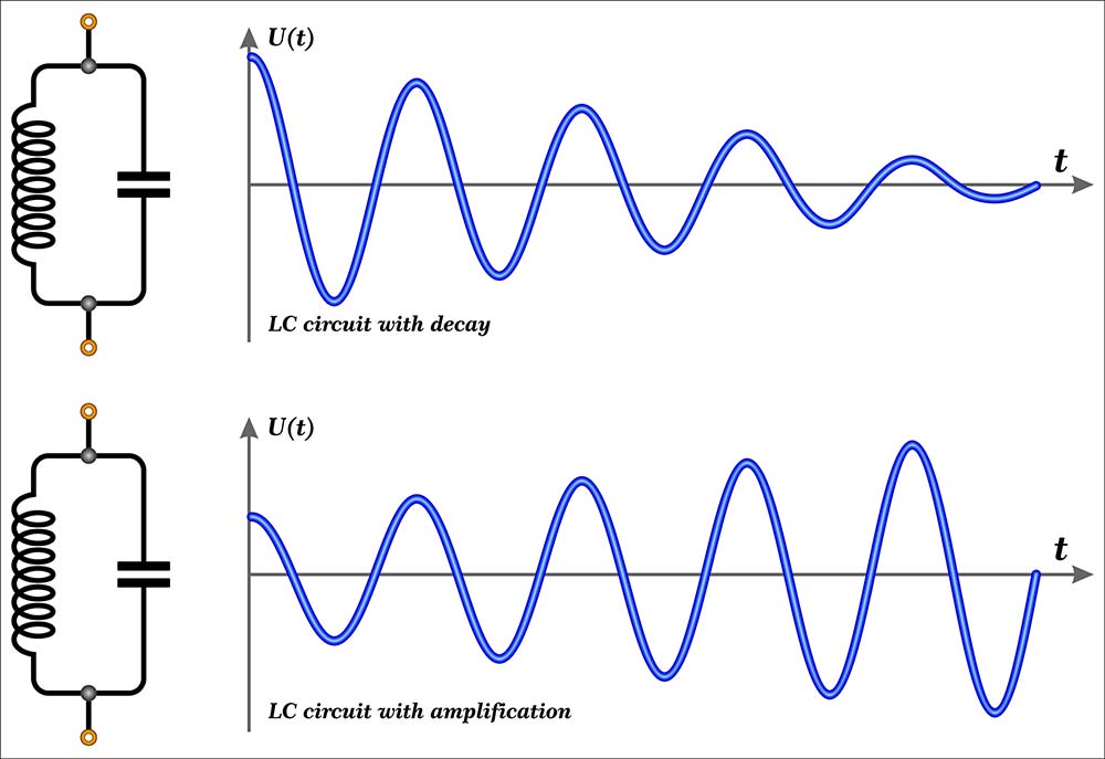
An LC circuit’s AC waveform with decay (without an amplifier) versus with an amplifier
The signal output from oscillators is always periodic, but amplifiers can generate periodic or non-periodic signals.
Also, amplifiers require negative feedback and require an input to operate. However, oscillators use positive feedback and don’t need an external AC signal to generate the oscillations.
Conclusion
To summarize, oscillators generate continuous periodic waveforms when you apply a specific frequency. LC oscillator, particularly, is a harmonic or sinusoidal oscillator that generates high-frequency sine waves. The waves are later applicable in radio frequency applications. In such cases, FETs or Bipolar transistors act as the transistor amplifier. And you use them to build an amplifier stage.
The article further elaborates on the types of LC oscillators, such as Clapp and Colpitts oscillator and their circuits.
Undeniably, there is still more to LC oscillator technology than we have highlighted today. Therefore, contact us if you wish to air your concerns and views. We’ll be happy to help.
Special Offer: Get $100 off your order!
Email [email protected] to get started!