Contents
Benefits and Applications of Electrical Transformers
- Circuit isolation: a transformer can isolate a device from the power grid and disconnect it from the earth. Therefore, it protects anyone who might touch loose wires or electrified surfaces.
- Converting voltage and current without affecting overall power: you can use them in the power grid to reduce power loss.
- Amplification of wave inputs
- Converting the distribution wiring electricity to a suitable voltage and current for a particular device
What does an electrical transformer look like?
An electrical transformer usually looks like a large metal box or cylinder. Pole-mounted transformers are cylindrical and often gray or green, while ground-mounted ones are rectangular and enclosed. They feature cables, bushings, cooling fins, and are marked with warning labels. Inside, they have a core and windings that transfer electrical energy.

Magnetic ferrite core transformer detail on beige printed circuit board
PCB transformers can mount on printed circuit boards as electrical components, also known as PCB-mounted transformers. Since most PCBs work below the power electronics range, most PCB transformers amplify a signal or convert electricity.
Special Offer: Get $100 off your order!
Email [email protected] to get started!
How Do Transformers Work?
As mentioned earlier, transformers transfer electricity from one circuit to another. Now, let's see how transformers work.
A transformer has three main parts, including electronic components and magnetic components:
- The primary coil
- The core
- The secondary coil
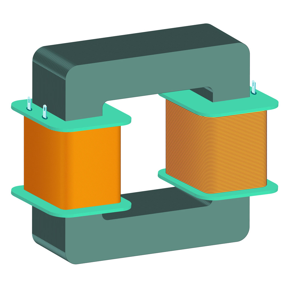
A simple transformer model
The steps below briefly explain how a transformer alters the output voltage.
- First, when electricity passes the primary coil, it induces a magnetic flow within the metalcore.
- Next, the magnetic flow reaches the secondary coil.
- Finally, the magnetic flow induces an electric current in the secondary coil.
In an ideal transformer, you can calculate the voltage and current of the second circuit using the following equation:
In the equation above, NP and NS represent how many rounds the coil wraps around the core. Those Numbers indicate how much you are amplifying the voltage.
The principles stated above apply to PCB transformers, just like any other.
PCB Transformer Composition
Inside any PCB-mounted transformer, two coils are the primary coil and the secondary coil. These coils are just coated copper wires tightly wrapped around the magnetic core. Moreover, steel or another magnetic alloy serves as the magnetic core material.
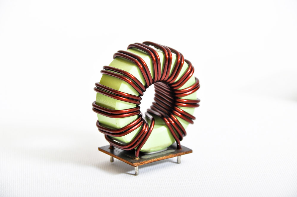
Transformer copper coil
Transformer designs often rely on innovative PCB coil designs to ensure optimal performance and efficiency. For more insights into these designs, explore our detailed guide on PCB Coil.
Transformers also have terminals and an outer casing. Since you use PCB transformers on circuit boards, there are two methods to mount the transformer onto the PCB:
- Surface Mounted Transformers:
Manufacturers design SMT/SMD transformers so you can solder them to the PCB directly. The soldering paste might loosen up if exposed to extreme heat. - Through-hole transformers:
As the name implies, you need to pass the leads through the PCB holes and solder the tips to the other side of the PCB.
PCB transformers are also vital components in modern flexible PCB designs, which offer enhanced versatility and durability in various applications. To learn more, visit What is Flexible PCB.
PCB Transformer: Main PCB-Mount Transformer Specifications
The following types of electrical equipment are the most common circuit board transformer types:
- Primary and secondary ratings:
The rating indicates how much the primary and secondary voltage and current are. First, you have to check the output voltage. Then, check if the design current is below the transformer limits. Also, note that the more the power density, the more heat will discharge from the circuit. - Power rating and efficiency:
Power rating determines the current type, AC or DC, and indicates how much power the transformer can handle. The voltage frequency is another important factor that you have to consider. Transformers also play a critical role in high-speed PCB designs, where managing power delivery and signal integrity is essential. For more information, visit our guide on High-Speed PCB Design.
Power efficiency tells you the direct current efficiency under a nominal load. - Form factor:
A transformer can lay flat or stand vertical on the board. Vertical transformers save space, but they are prone to vibration. Proper layout considerations are crucial for minimizing such issues and ensuring optimal performance. For tips on creating effective layouts, explore our PCB Layout Guide for Beginners. - Mounting style:
Some transformers are SMT type; you have to solder these transformers to the PCB surface; hence we call them surface mount technology. On the other hand, through-hole transformers require passing the leads through PCB holes and soldering them on the opposite side of the board. The latter offers better resistance to extreme heat. - Cooling mechanism:
Unlike power electronic transformers, PCB-mounted transformers use much less power. Therefore, they generate less heat and don't need a particular cooling system. However, planar PCB-mounted transformers can hold a heat sink on top of the piece. - Inductance:
Simply put, inductance determines how well the transformer couples the two circuits. Inductance is also a part of DC-DC converter circuits; in other cases, power efficiency indicates the coupling performance of the transformer implicitly. For a deeper understanding of how transformers interact with transmission lines on PCBs, explore the details of PCB transmission line design.
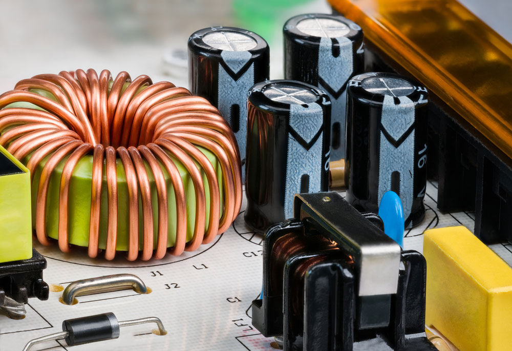
Transformer on a PCB detail
PCB Transformer: Types of PCB Mount Transformers
The electrical apparatus comes with different sizes of power converters and various applications.
- Audio transformers:
You can use these tools to convert sounds and signals from about 300Hz to 20kHz. - Autotransformers:
This electrical equipment has only one winding which acts as both primary and secondary coils. Therefore, these efficient power convertors have different secondary voltage settings. You can connect other taps on the transformer for different conversion ratios. However, these transformers don't provide isolation since there are no separate coils. - Balun transformers:
This device allows balanced and unbalanced lines to be interfaced without disturbing the impedance arrangement of either stripe. - Current sense transformers:
These electric transformers detect and measure current in the primary winding and produce a proportional secondary current in the secondary winding. - Flyback transformers:
FBT or line output transformers (LOPT) is a special transformer that creates high voltage saw-toothed signals at relatively high voltages.
- Interface transformers: We use these electric transformers in telecoms and communication circuits with an isolated signal. These transformers are also crucial for embedded systems where space and functionality are tightly integrated. For more on these applications, visit Embedded PCB.
- Lighting transformers: These can generate suitable power for lighting and illumination systems. Transformers play a crucial role in powering LED-based systems, ensuring efficiency and stability. To learn more about the design and functionality of lighting systems, visit our comprehensive guide on LED PCB.
- Medical transformers: Medical equipment has strict regulations and tight safety guidelines. Therefore, medical transformers are safe-to-use in operating rooms for medical and surgical applications. Ensuring these safety standards often involves specialized PCB designs tailored for medical use. To explore these applications further, visit our detailed guide on Medical PCB.
- Power transformers: These transformers power up the power supply of an electric device. Manufacturers, for example, utilize power transformers to power audio systems such as speakers and amplifiers.
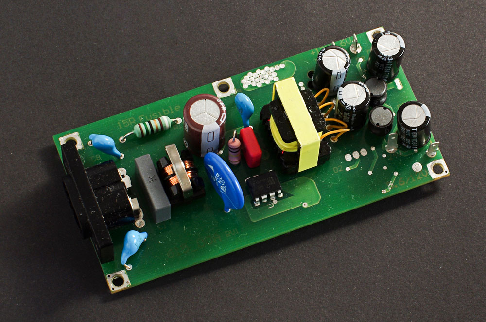
Power supply PCB printed circuit board.
- RF transformers: Radio frequency transformers can match impedances, isolate DC currents between circuits, and perform current or voltage step-ups or step-downs. Designing transformers for RF applications requires careful consideration of signal integrity, impedance matching, and frequency optimization. For an in-depth look at these design considerations, explore our guide on RF PCB Design.
- Resonant transformers: We use resonant transformers in radio circuits as bandpass filters and switching power supplies.
- Switch mode transformers or switching transformers operate under low voltage supplies. We use them in industrial and domestic applications.
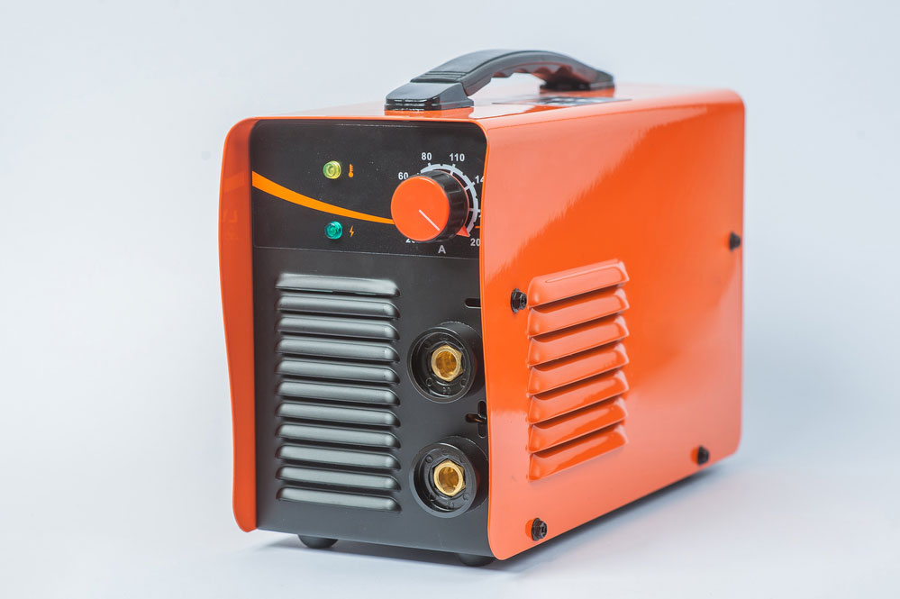
Electrical transformer
Back to Top: PCB Mount Transformer
Special Offer: Get $100 off your order!
Email [email protected] to get started!


