74HC14 belongs to the 74xxxx family of integrated circuits. This family of ICs has logic gates. For the 74hc14 IC, the logic gates perform a Y=A boolean function. Another name for the 74hc14 IC is the HEX inverting Schmitt trigger. The integrated circuit comes in six self-sufficient trigger input inverters with standard push-pull outputs. This article will discuss the 74HC14 IC, its features, and how to use it.
Contents
74hc14 Pinout Configuration
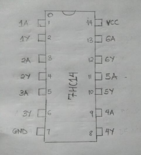 (Schematic diagram of the7hc14 pinout) The 74hc14 IC comes in different packages. Importantly, it is a 14 pin device. The table below describes each pin configuration. ( G= Gate.)
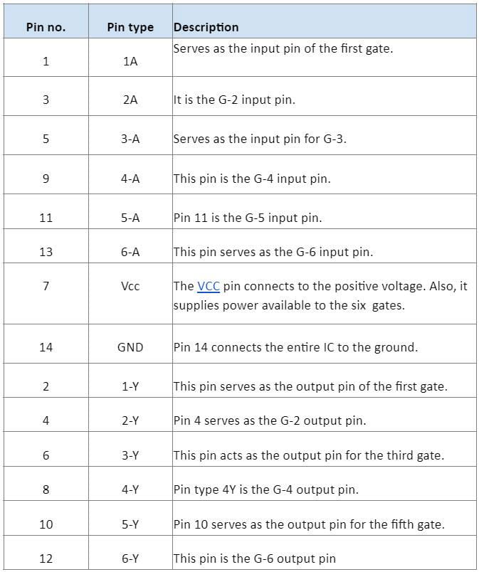
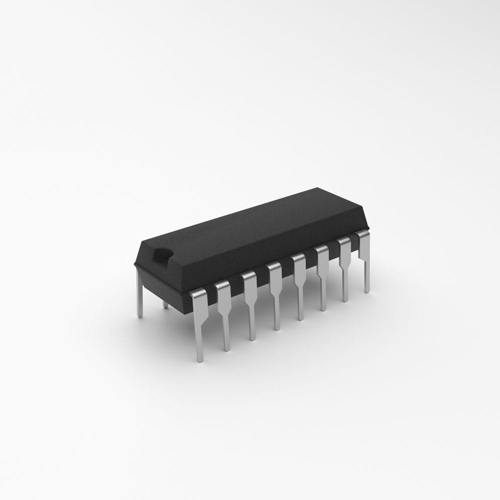
(an IC showing its pins)
74HC14 Technical Specifications and Attributes
- First, this device has TTL-type outputs with an output drive capability of 10LSTTL loads and a maximum ESD of 2kV.
- Second, depending on the supply voltage, the 74hc14 IC has a typical rise time and typical fall time of 85-652ns.
- Third, the 74hc14 IC is a lead-free device with the ability to associate with CMOS, NMOS, and TTL.
- Also, the maximum current flow from each gate is 25mA. However, the VCC and GND allow a total current to flow through them up to 50mA.
- Moreover, the 74hc14 device has a working voltage range of 2.0v to 6.0v. However, its operating voltage range is between -o.5v to +7.0v.
- Additionally, these electronic components have an average working temperature of -55⁰C to 125⁰C and noise immunity.
- Finally, the 74hc14 module is compatible with the standard JEDEC requirements and chips with 60FETS or equivalent chip gates.
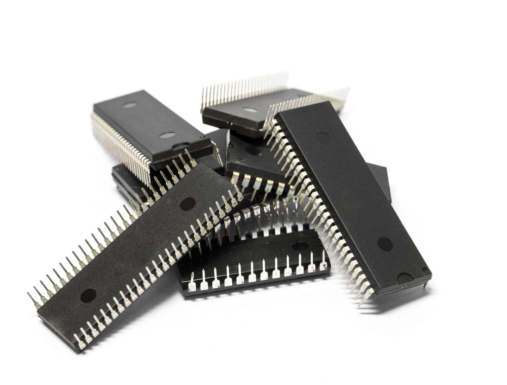
(integrated circuits)
74hc14 equivalent IC
These include; MC14584 and CD40106.
Special Offer: Get $100 off your order!
Email sales@ourpcb.net to get started!
Projects to use 74hc14
There are three cases where you can use the 74hc14 IC.
Case 1.
You can use the 74hc14 Ic in situations where you need to convert the sinusoidal signal waveforms into square waves. When using Schmitt trigger gates, you can change a sinusoidal wave or triangular waves into a square wave output.
Case 2.
This second case occurs when you need a logic inverter in your project. The 74hc14 chip contains inverter Schmitt trigger gates which give out an output which is the negated logic input. This property is necessary when getting inverted logic for controllers and digital electronics.
Case 3.
When your project generates too much noise, you need to introduce the 74hc14 IC. Notably, this device operates by eliminating any noise in electronic systems. Therefore, it’s essential since noise causes many errors in digital electronics. 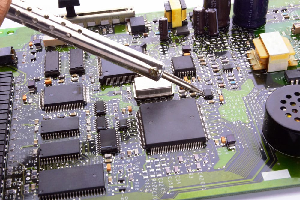
(an electronic circuit with integrated circuits.)
How to use 74hc14?
You should know that each gate can independently function. To test this theory, first, select a single gate. Then, connect the power to the IC. Alongside the energy, provide an analog signal at the input. 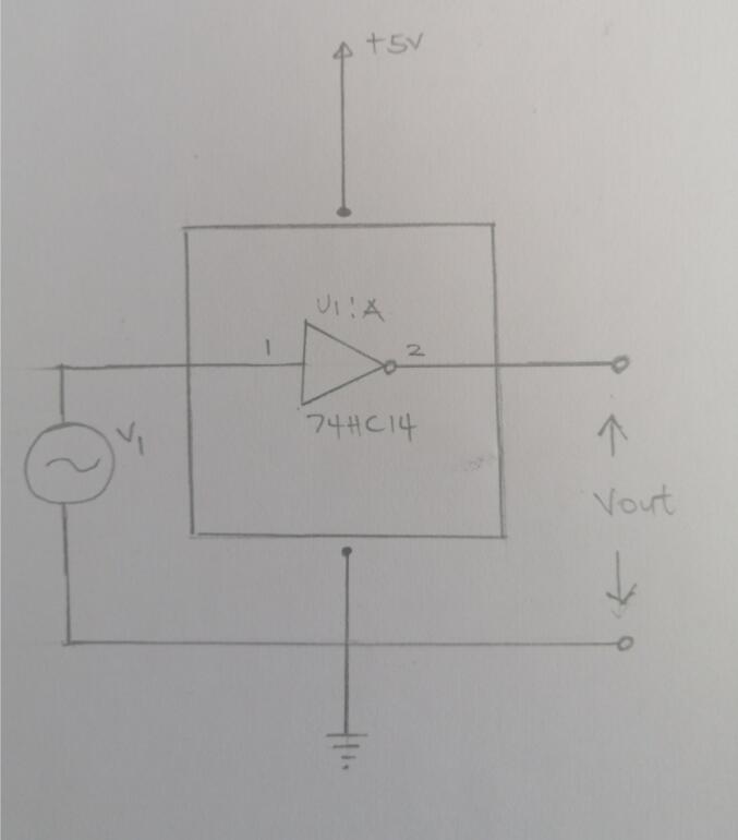
(Schematic diagram of 74hc14 in a circuit.)
Once you achieve the connection, you will understand the working principle of the Schmitt trigger gate. The regulation states; the output of the Inverting Schmitt trigger output is low only when the voltage level of the input signal passes the threshold voltage. To clarify, until the moment when the input voltage reaches the threshold voltage, the output voltage will always be high. But, this voltage drops once it gets to the threshold voltage. Further, the output(v) remains LOW until the input(v) falls to a LOW voltage. When this change occurs, the result (v) rises. Notably, this is a continuous and interrupted cycle, provided there’s a power supply to the chip. 
(an electronic integrated circuit chip)
74HC14 Switching Time
Switching time is the time delay it takes a gate to provide an output of a given input. Importantly, individual gates take a specific amount of time for changing functions. During this switching, you can detect two types of time delays. These time delays are the fall time and rise time. A time difference occurs between when the device input is high, and the output is low. This type of response is the rise time. It takes about 95ns. Similarly, the time difference between a logic input being low to its output going high is the fall time. This delay also takes about 95ns. Therefore, in available cycles, you will have a total time delay of 190ns. These time delays occur when the chip is operating at higher frequencies. The system experiences noise, trigger-malfunctions, and extensive errors whenever you exceed optimum operating frequency. 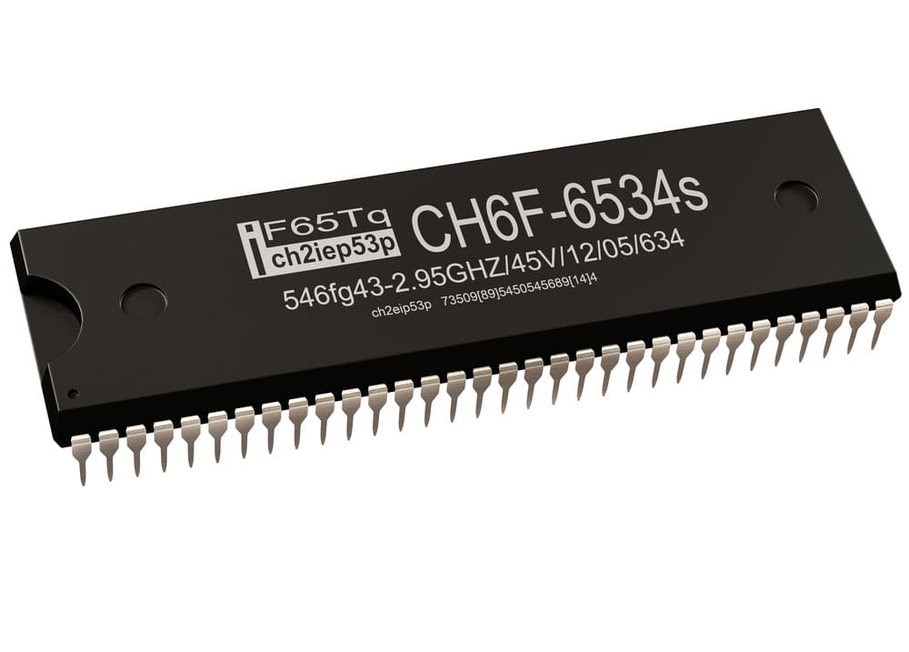
(an integrated circuit chip.)
Applications
- Firstly, use the 74hc14 IC in building computers.
- Secondly, apply the Integrated Circuit in general-purpose logic.
- Thirdly, the IC is useful for building TV, Set-top boxes, and DVDs
- Lastly, it is a requirement in networking and digital systems.
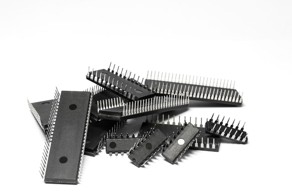
(IC chips on a white background.)
Summary.
We hope this article helps you answer 74hc14 related questions. Our team is ready to help you! For more information about this or any of our articles, please do not hesitate to contact us.
Special Offer: Get $100 off your order!
Email sales@ourpcb.net to get started!