To improve your radio signal reception, make an FM antenna booster. Start by gathering the necessary components such as capacitors, resistors, inductors, and a C2570 transistor. Carefully assemble these parts into a circuit, ensuring that the input antenna receives the weak FM signal, which is then amplified by the booster before being transmitted through the output antenna for improved FM reception. Follow our step-by-step guide below.
Contents
- Key Takeaways
- How do FM Antenna Boosters Work?
- Practical Tips for Improving FM Signal Reception
- How to Build an FM Antenna Booster
- Tools Needed
- Required Components
- Explanation and Background
- FM Antenna Booster: Step-by-Step Construction Guide
- Types of FM Antenna Boosters
- Using Your Booster to Build Other Radio Frequency Devices
- Partner with OurPCB for Custom FM Antenna Boosters
- FM Antenna Booster: How to Improve Your Radio Signal Reception FAQs
- How far can an FM antenna booster cover?
- How much does an FM antenna booster cost?
- What should I look for in an FM antenna booster?
Key Takeaways
- To make an FM antenna booster you’ll need basic tools such as screwdrivers, a utility knife, and a ruler, along with specific electronic components, and a 12V power source.
- FM antenna boosters, also known as FM amplifiers, enhance weak radio signals by amplifying the reception.
- FM antenna boosters amplify weak signals by passing them through a circuit — fine-tuning is available by using variable capacitors for optimal performance.
How do FM Antenna Boosters Work?
It’s important to grasp the basics of FM transmission to understand how an FM antenna booster works. Every radio station broadcasts its signal at a unique frequency, known as the carrier wave. To transmit audio, the station modulates this carrier wave, embedding the audio signal within it. Your FM receiver detects and decodes these radio waves, using an antenna to capture them.
However, when signals are weak, the radio receiver or FM radio antenna may not capture them clearly, resulting in static or broken audio. This is where an FM antenna booster comes in: by amplifying the signal before it reaches the FM receiver, the booster minimizes interference, strengthening audio clarity and signal reliability. In some devices, FM boosters are built directly into the receiver, while others are separate add-ons that can be attached to enhance an existing system.
OurPCB provides printed circuit board assembly (PCBA) services that can help design and manufacture custom FM antenna boosters, supporting optimal functionality and precise signal amplification for your projects. This guide explores the creation of a DIY FM antenna booster. With basic tools, low-cost components, and careful assembly, you’ll be able to construct an effective signal booster suitable for various applications.
Special Offer: Get $100 off your order!
Email sales@ourpcb.net to get started!
Practical Tips for Improving FM Signal Reception
In addition to using a booster, there are effective methods to improve FM reception without complex setups:
- Antenna Position: Place your FM antenna as high as possible, ideally near a window, to reduce interference from walls and other obstructions.
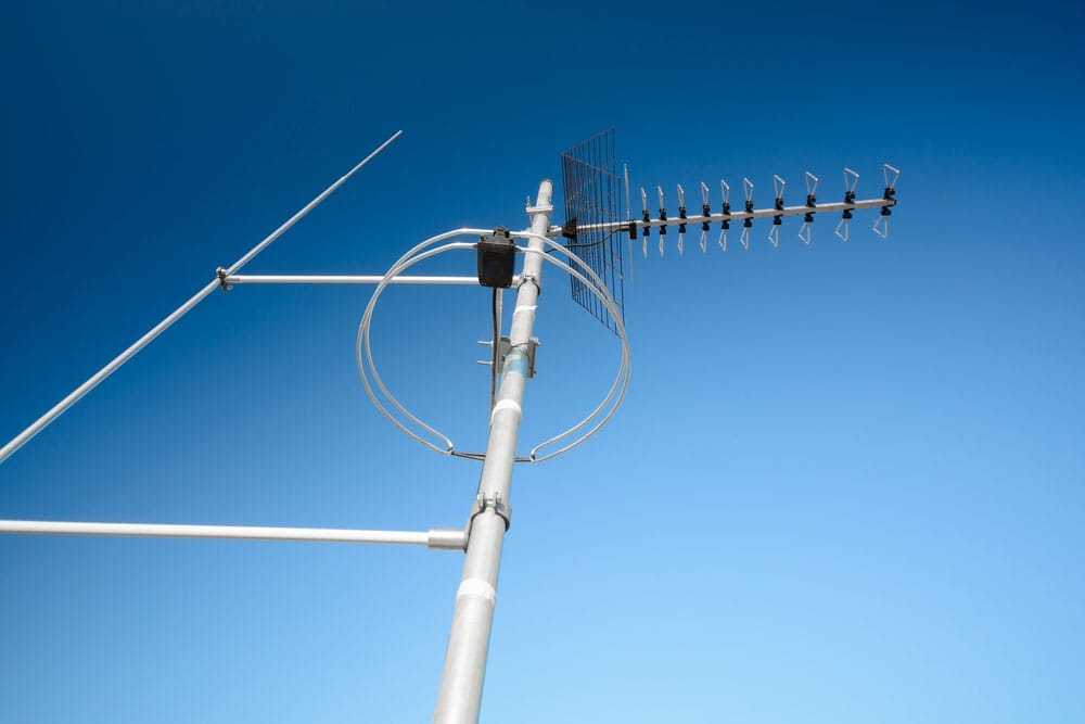
- Use Outdoor or Long-Range Antennas: If indoors, consider moving your antenna outdoors or using a long-range directional antenna for stronger reception.
- Reduce Nearby Electronics: Electronics like Wi-Fi routers or LED lights may cause interference. Place the radio away from these devices to enhance signal clarity.
How to Build an FM Antenna Booster
Building an FM antenna booster requires a handful of affordable components and tools. Notably, a booster’s gain determines its strength in amplifying signals. For remote locations, choose a high-gain booster for best results. To simplify this project, we’ve kept the design as cost-effective as possible while ensuring reliable FM signal amplification.
Tools Needed
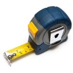
- Ruler or tape measure: For precise measurements
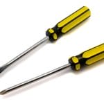
- Flathead and Phillips screwdriver: For assembly and adjustments
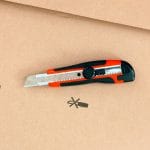
- Utility knife: To strip wire and trim components as needed
Required Components
- 5.6pF capacitor x2
- 22pF variable trimmer capacitor x2
- (3 + 1) turn inductor: The inductor should be wound with 20 SWG enameled copper wire on a 5 mm diameter former.
- 27K Ohm resistor x2
- 1nF capacitor
- 1K Ohm resistor
- C2570 transistor: This VHF/UHF transistor is central to signal amplification.
- Ground wires x3
- 12V power source: Use a battery pack or an AC/DC adapter
- 0.1uF capacitor
- 10pF capacitor x2
- 3-turn inductor
- Input and Output Antennas: These antennas receive and transmit the amplified FM signal
Explanation and Background
This project is based on a C2570 transistor circuit that works by receiving a weak signal from the input antenna, amplifying it through the transistor, and then emitting it through the output antenna. The input antenna receives the initial FM signal, which passes through a series of capacitors, resistors, and inductors, each playing a specific role in conditioning and boosting the signal or FM radio reception.
Key components like trimmer capacitors (VC1 and VC2) allow you to fine-tune the circuit for optimal functionality. Both trimmers should be rated at 22pF to ensure even performance. The inductors form a crucial part of the amplification process. The primary inductor is wound as a 2-segment coil, with three turns in one segment and a single turn in the other, on a 5 mm diameter former. Each inductor must be tapped to the ground side of the circuit for stability.
FM Antenna Booster: Step-by-Step Construction Guide
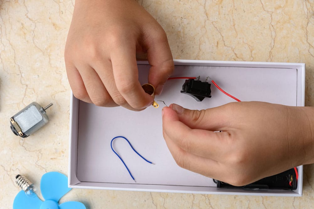
The following steps will guide you through the assembly of your FM antenna booster. It’s helpful to set up your components on a breadboard initially to experiment and make adjustments.
| Step | Description |
| 1. Connect the Input | Begin by running a wire from the live side of your input antenna to the first capacitor (C1). |
| 2. Inductor and Capacitor Configuration | Connect C1 to the first inductor (L1) and the second capacitor (C2). Add the first variable capacitor in parallel with L1 to form an inner parallel circuit, and ensure this is grounded. |
| 3. Transistor Wiring | Run a split wire from C2. One end goes to the first resistor (R1), while the other connects to the C2570 transistor. Be sure to ground the transistor for proper function. |
| 4. Connecting the Resistors | Link the first resistor (R1) to the second (R2) and then to the third resistor (R3), forming a sequence. |
| 5. Grounding Capacitors | Connect the junction of R2 and R3 to the third capacitor (C3) and ground it. Then connect R3 to the sixth capacitor (C6) and ground it as well. |
| 6. Power Setup | Attach the sixth capacitor to the 12V power supply. |
| 7. Additional Parallel Circuits | Create a parallel circuit by connecting the second resistor to the fourth and fifth capacitors in series. |
| 8. Output Configuration | Add another parallel connection with the second inductor and variable capacitor, grounding this circuit. Finally, connect the fifth capacitor (C5) to the output antenna. |
Each step plays an essential role in stabilizing and fine-tuning the signal as it moves through the circuit. Pay attention to the placement of each component, especially the inductors and capacitors, to ensure efficient FM signal flow and amplification.
Your initial build may look rough and temporary, especially if assembled on a breadboard. Later, you can enhance your booster’s durability by designing and fabricating a custom PCB layout. OurPCB’s PCBA services can assist with this step, creating a more stable and professional booster unit.
Types of FM Antenna Boosters
Some FM boosters are omnidirectional (receiving signals from all directions), while others are directional, focusing on one area for stronger reception.
- Directional vs. Omnidirectional: Choose based on your area’s signal strength and whether you need to focus on a specific station.
- Gain and Amplifier Power: Boosters with higher gain and power are ideal for rural or developing areas where FM signals are weak.
Using Your Booster to Build Other Radio Frequency Devices
Once you’ve built this FM antenna booster, you’ll have the foundational knowledge to construct other types of radio frequency boosters. By modifying the circuit, you could design amplifiers for different signal ranges and device types, such as Wi-Fi or Bluetooth boosters, which operate on similar principles.
Partner with OurPCB for Custom FM Antenna Boosters
OurPCB offers high-quality PCB design and assembly services to bring your custom FM antenna booster project to life. From PCB layout to component assembly, OurPCB can help transform your prototype into a professional-grade device. Contact OurPCB today to learn more about our PCB solutions for your FM or radio signal amplification needs.
FM Antenna Booster: How to Improve Your Radio Signal Reception FAQs
How far can an FM antenna booster cover?
Coverage largely depends on the build quality and power output of the device. While an average FM radio station has a range of 30 to 40 miles (50 to 60 km), a 1000-watt antenna booster can extend reception by up to 12 miles (19.3 km), depending on terrain and interference.
How much does an FM antenna booster cost?
Prices vary based on features, power, and build quality. Vehicle FM antenna boosters typically cost $14 to $20, while indoor models range from $20 to $50.
What should I look for in an FM antenna booster?
When purchasing an FM antenna booster, prioritize these factors:
- Reception Power: The booster should be capable of capturing signals from long distances.
- Gain: Look for a high-gain booster, as this determines how well it amplifies weak signals.
- Directivity: Omnidirectional boosters capture signals from all directions, while directional boosters focus on signals from a specific direction. Choose based on your reception needs.
- Build Quality: Opt for durable materials and construction to ensure longevity, balancing quality with cost.
Back to Top: FM Antenna Booster | How to Improve Your Radio Signal Reception
Special Offer: Get $100 off your order!
Email sales@ourpcb.net to get started!