Contents
- Key Takeaways
- What are TL431 Circuits?
- What are the Characteristics of TL431 Circuits?
- TL431 Circuits Working Principle
- How the TL431 Circuits Works?
- 9 Applications That Use TL431 Circuits
- 1. Adjustable Regulator Circuit Using TL431
- 2. TL431 Precision Reference Voltage Source
- 3. Voltage Detector Circuit Using TL431
- 4. TL431 Overvoltage Protection Circuit
- 5.TL431 Constant Current Source Circuit
- 6. TL431 Comparator
- 7. TL431 Voltage Monitor
- 8. TL431 Controllable Shunt Features
- 9. TL431 Switching Power Supply
- OurPCB: Experienced PCB Assembly Services
- TL431 Circuits: Applications and Design Tips FAQs
- What is the difference between Zener and TL431?
- What can I use instead of TL431 transistor?
- What is a voltage detector circuit using TL431?
Key Takeaways
- TL431 circuits are versatile for power supply control and voltage regulation.
- They function as adjustable shunt regulators and voltage references with high precision.
- Applications include overvoltage protection, constant current sources, and voltage monitoring.
- Adjustable voltage output (2.5V to 36V) is achieved with external resistors for flexible designs.
- Voltage accuracy depends on resistor precision, with fine-tuning available for stable references.
OurPCB's guide provides detailed insights and design tips for using TL431 circuits effectively, whether you're a beginner or an experienced designer.
What are TL431 Circuits?
A TL431 circuit, which comes in switch-mode power supplies loops, is a three-terminal integrated circuit. You can also use it as an adjustable precision shunt voltage regulator. So, you can join a TL431 actual power supply feedback circuit with an external voltage divider. Also, you can regulate 2.5 - 36 voltage ratings—with a maximum standby power supply current of 100mA and junction capacitor.
A TL431 circuit functions as an adjustable, precision shunt voltage regulator and often appears in power management and switch-mode power supply applications. As a non-inverting reference, it operates similarly to an op-amp with a variable voltage reference, allowing for flexible control between 2.5V and 36V. By configuring the circuit with an external voltage divider and controlling base current, the TL431 can serve as either a fixed voltage regulator or be adjusted as needed for variable voltage regulation. For more technical specifications and setup details, refer to the TI datasheet, which includes essential guidelines for achieving optimal precision and stability in your designs.
Special Offer: Get $100 off your order!
Email [email protected] to get started!
What are the Characteristics of TL431 Circuits?
Before we dive into how this circuit works, here are the features of the TL431 circuit.
It has a good reference voltage tolerance at a temperature of 25 °C for:
- Standard grade tolerance and output capacitor (2%)
- A grade tolerance and traditional capacitor (2%)
- B grade tolerance (2%)
- The TL431 also has a Vref to 36 v adjustable output voltage
- Can withstand the effects of temperature from −40 °C to 125 °C
- Has a typical temperature drift (TL43xB):
- 14 mV (I Temp, Q Temp)
- Six mV (C Temp)
- Generates a low output noise
- Has a typical output impedance of 0.2-Ω
- Has a 1mA to 100 mA sink-current capability
- The type of capacitor in TL431 has a varying capacitance with voltage
TL431 Circuits Working Principle
As we mentioned earlier, the TL431 is essentially a voltage controller with an 8-pin IC package. But that's only at a fundamental level. Going deeper, we find that the TL431 is an alternative for the adjustable Zener voltage regulator. It also supports surface-mounted SOT23-3 package and transistor-like package.
During the development of a PCB board fabrication, TL431 circuits can be configured with an external precision divider resistor and various package options to meet specific voltage regulation requirements.
Plus, you can set the output voltage with:
- A variety of packages
- Larger package
- An external precision divider resistor
But there's more!
The first capacitor of the circuit also works with a reverse-biased diode and a diode for reference.
How the TL431 Circuits Works?
So, how does it work?
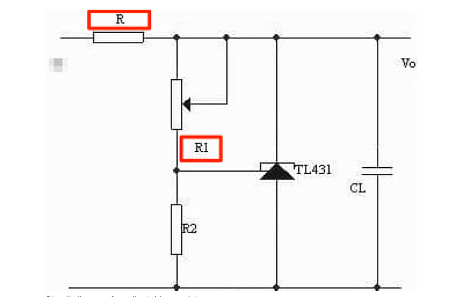
The circuit determines the resistance values of both R1 and R2 resistors. Plus, it generates feedback and poor resistor tolerances—which is dependent on the partial pressure of Vo.
When Vo increases, the feedback will also increase and the shunt of TL431. In essence, the increase in shunt reduces the pressure and detailed schematic of the Vo.
Additionally, you need to do something when the REF terminal voltage and previous schematics is equal to the reference voltage.
Here, it's ideal to keep the negative feedback and internal schematic of the circuit stable. At this point, you'll have Vo = (1+R1/R2)Vref. Also, you can get any output voltage and maximum currents between 2.5v to 36v. And it happens when you choose different values for your R1 and R2 resistors.
Note, there are some necessary conditions you've to meet before the TL431 can work. One of them involves selecting a suitable resistor, copper anode and basic level of internal anode. Hence, the current passing through the anode pins and cathode of your TL431 should be greater than 1mA.
To sum it up, the circuit's output voltage and output sampling increase when the input voltage increases. In short, it's the working principle and the level of chip decapping of the TL431.
Furthermore, you can adjust the internal circuit to increase the current that flows through it. Plus, the current limit circuit also increases the voltage drop of the current limiting resistor.
So, to achieve voltage regulation;
The output voltage = input voltage - current-limiting resistance.
9 Applications That Use TL431 Circuits
Here are nine applications using the TL431 circuit.
| Application | Description |
|---|---|
| Adjustable Regulator | Regulates 2.5V-36V output; current limit of 100mA, adjustable with transistors. |
| Precision Reference | Stable Vref source for power supplies; prevents self-excitation in capacitive loads. |
| Voltage Detector | Sets output at fixed levels; lowers output when input drops, creating feedback. |
| Overvoltage Protection | Triggers a thyristor and fuse at set Vref to prevent overvoltage damage. |
| Constant Current Source | Pass-series current regulation at Vref (2.5V); useful for current-limiting. |
| Comparator | Switches optocoupler at threshold voltage, using Vref at 2.5V for control. |
| Voltage Monitor | LED indicator at set voltage, often used in battery chargers for full-charge indication. |
| Controllable Shunt | Manages small loads (lights, relays) by adjusting shunt based on REF terminal voltage. |
| Switching Power Supply | Stabilizes DC output through feedback via optocoupler, used in PWM control. |
1. Adjustable Regulator Circuit Using TL431
The adjustable regulator circuit application and switching frequency is quite simple when you're using the TL431 integrated circuit.
So, the circuit can regulate the poor gain and voltage between the range of 2.5v - 36v voltage rating. Plus, it depends on the following:
- Input supply voltage
- The board layout
- Change of the component values of R2 and R1
Also, the adjustable regulator circuit uses the following formula and block diagram to calculate;
V0 = Vref(1+R1/R2), Vref = 2.5v.
However, the current has a limit of 100mA. Therefore, you can enhance the current with a transistor, booster transistor, or a couple of transistors if you choose.
Can you relate this circuit's voltage to (Vi — Vo)? Then, the power consumption of R increases when the voltage difference is immense. Then, it becomes a programmable shunt regulator with semiconductor technology with temperature-stabilized bandgap.
2. TL431 Precision Reference Voltage Source
The precision reference voltage source uses the TL431, which is an unusual choice, on the control circuit of isolated power supplies. Hence, you can use the TL431 to provide a precision reference voltage and configure it as an analog circuits controller.
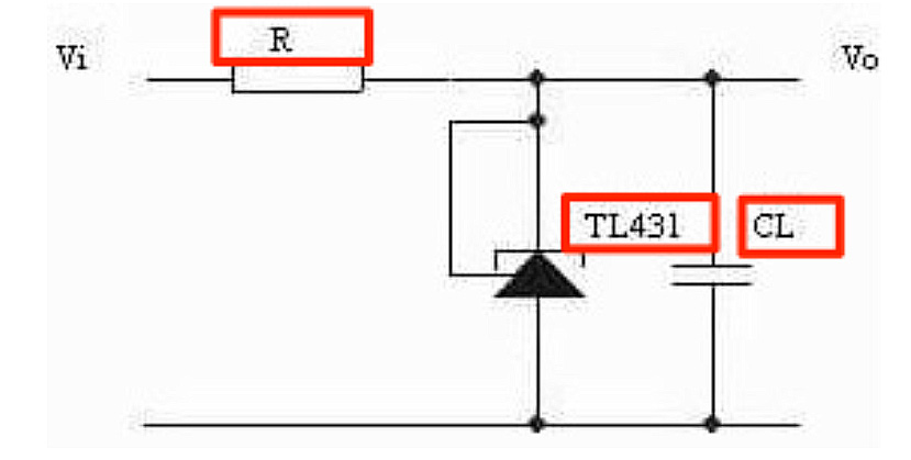
Why? Because it features an onboard error amplifier.
Additionally, the precision reference voltage source circuits feature a huge output transistor, stable reference, and good temperature stability. However, ensure you watch out for the value of CL when connecting capacitive loads. By doing so, you can prevent self-excitation and gain a stable voltage reference (Vref).
3. Voltage Detector Circuit Using TL431
The voltage detector circuit is another simple pressure level circuit you can build with the integrated circuit, TL431. So, you can use a 5v power supply in a digital circuit, bipolar transistors and real transistor. Plus, the general feeding signal input will become a high-class logic—releasing a 5v output.
So, when the level logic is low, the output level reduces to 1.8v. Thus, it's easy to assemble this circuit with adjustable shunt regulator to achieve a feedback loop and the results you want.
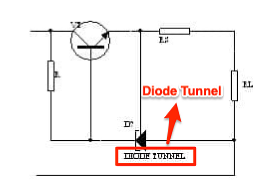
4. TL431 Overvoltage Protection Circuit
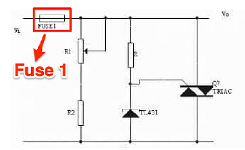
As the name implies, the circuit offers protection from high voltages, and it handles temperature compensation for analog chips. The equipment with this pin input circuit automatically shuts down when its power crosses the fixed voltage value. The IC balanced comparator voltage references serve as a low-temperature adjustable Zener diode. Plus, you can program it from Vref to 36v—with the aid of two external resistors.
This single layer circuit has a substantial current range of 1.0 mA to 100 mA for operations and a typical dynamic impedance of 0.22 W. So, when Vi passes the set feedback voltage limit, it triggers the TL431. While this happens, the thyristor turns on to generate a sizable pulsating current. This larger variety current blows a fuse to protect the rear circuit. Hence, the V protection point is equal to (1+R1/R2)Vref.
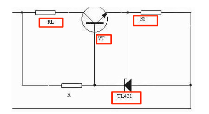
5.TL431 Constant Current Source Circuit
You can use the TL431 shunt regulator as a pass-series constant current regulator. The most significant factor in this output is the RCL and—not the R1. Though R1 has its formula, it's not that important.
The formula is Vref = 2.5 V.
The value of the constant minimum voltage depends on the external resistance and positive voltage references.
Therefore, it's essential to consider the margin when selecting a power transistor for this circuit. Moreover, you can use this current source as a current limiter if you don't connect it to a stabilized circuit.
6. TL431 Comparator
The TL431 Comparator conducts and switches on an optocoupler. And it happens when the voltage across it passes a limit.
But remember that the TL431 has three pins. VT measures the voltage across—which is proportional to the output voltage. Thus, it cleverly utilizes the critical voltage of Vref = 2.5v. Also, the output and input waveforms track well because of the distance of the TL431.
7. TL431 Voltage Monitor
The TL431 voltage monitor is another application with a single purpose. Here, the circuit lights up an LED when it reaches the target voltage rating. Hence, it's perfect for battery chargers, like the laptop power adapter—indicating when the batteries get fully charged.
Also, phone chargers are good examples of power devices with this circuit.
So, the voltage monitor uses a simple High limit = Vref (1+R1/R2). Here, the high limit here is the target voltage that lights up the LED with emitter voltages when hit.
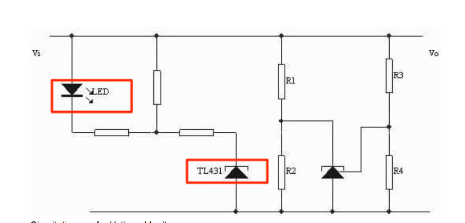
The voltage reference is at 2.5 volts in the TL431. Also, the R1 and R2 form a voltage divider that allows you to set the desired high limit range.
8. TL431 Controllable Shunt Features
For this application, something happens when the voltage at the REF terminal goes through a slight change. It changes the shunt from the cathode voltage. Also, the process changes the anode within 1–100 mA. So, it affects both the cathode current and the anode current.
With the controllable shunt characteristics, you can use small voltage changes to control indicator light, relays, etc. Plus, you can even drive current audio loads directly.
9. TL431 Switching Power Supply
Previous generation switching power supply designs featured a system that did one thing.
The TL431 sent back the output current to the alternating current input terminal after error amplification. However, recent technology allows most power supply industries to adopt a new scheme.
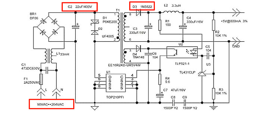
Here, the TL431 sends back the output as voltage feedback so it can amplify the error. Then, the sinking end of the TL431 drives the light-emitting section of the optocoupler. With this, you can obtain voltage feedback from the photocoupler. Also, you can use it to adjust the time of the PWM controller current mode. Thus, making the direct current output voltage stable.
OurPCB: Experienced PCB Assembly Services
TL431 circuits offer versatile applications, from voltage control and power supply control to acting as a programmable Zener diode with an internal reference (Vref voltage) for precision. Acting as a shunt regulator, the TL431 is a shunt that excels in power supply circuits and voltage monitoring. It achieves accuracy largely depends on the precision of your resistors—fine-tuning with series resistor R2 can help ensure stability.
If you're ready to use the TL431 to make precise power management circuits, OurPCB’s assembly services can support you every step of the way. With our experience and commitment to quality, we bring your circuit concepts to life, letting you focus on innovation while we handle the assembly details. Reach out to us today to start your project!
TL431 Circuits: Applications and Design Tips FAQs
What is the difference between Zener and TL431?
Unlike a Zener diode, the TL431 is an adjustable voltage comparator that allows for precise control of the desired output voltage using an external resistor divider. The TL431 offers flexibility with an adjustable Vref voltage from 2.5V to 36V, while Zeners have fixed voltage values.
What can I use instead of TL431 transistor?
A TL432 can be used as an alternative to TL431, as both are adjustable voltage comparator references with similar functions. The TL432 has a smaller package, ideal for designs with limited space around the TL431.
What is a voltage detector circuit using TL431?
A TL431 voltage detector circuit compares the divided voltage to its internal Vref voltage to indicate when regulated voltage is too high or low. When the input voltage is low, the circuit can activate an alert or control mechanism to stabilize the desired output voltage.
Back to Top: TL431 Circuits: Applications and Design Tips
Special Offer: Get $100 off your order!
Email [email protected] to get started!