As electronics continue to miniaturize while processing power increases, the resulting thermal challenges make high-Tg PCBs increasingly essential for modern electronic design.
Contents
- Key Takeaways
- What is a High-Temperature PCB?
- Understanding Glass Transition Temperature (Tg)
- Classifications of PCBs by Tg Value
- Why Tg Matters for PCB Performance
- Features of High-Tg and High Temperature PCBs
- Superior Thermal Stability
- Enhanced Mechanical Properties
- Excellent Electrical Characteristics
- Enhanced Reliability Factors
- Properties of High Tg Materials
- Key Material Performance Metrics
- High-Temperature PCB Applications
- Automotive Electronics Applications
- Aerospace and Defense Applications
- Industrial and High-Power Electronics
- Telecommunications and Networking
- LED Lighting and High-Power Illumination
- Heat Transfer in PCBs
- Radiation Heat Transfer
- Convection Heat Transfer
- Conduction Heat Transfer
- Integrated Thermal Management
- Material Selection for High-Temperature PCBs
- High-Tg Material Selection Framework
- Common High-Tg Material Types
- Assembly Considerations for High-Temperature PCBs
- Solder Alloy Options for High-Temperature Applications
- Best Practices for High-Temperature Assembly
- Modifying Existing Designs for High-Temperature Performance
- Why Heat Management is Necessary for Circuit Boards
- Preventing Thermal Expansion Damage
- Preventing Electrical Performance Degradation
- Preventing Oxidation and Chemical Degradation
- Ensuring Component Reliability
- Thermal Management Strategies for High-Tg PCBs
- Thermal Via Implementation
- Copper Layer Optimization
- External Thermal Management Integration
- The Coefficient of Thermal Expansion (CTE) and High-Temperature PCBs
- Understanding CTE in PCB Materials
- Critical CTE Relationships in PCBs
- CTE Before and After Tg
- Strategies to Mitigate CTE Challenges
- Manufacturing Considerations for High-Tg PCBs
- Lamination Process Requirements
- Drilling Challenges and Solutions
- Copper Plating Considerations
- Testing and Quality Assurance
- Design Considerations for High-Temperature PCB Applications
- Thermal Management Design
- Component Selection and Placement
- Advanced Layout Techniques
- Reliability Enhancement Techniques
- High-Tg & High Temperature PCB: FAQ
- What is the difference between Tg and Td in PCB materials?
- What is high-heat solder called in electrical applications?
- What is the Tg value of FR4 PCB and how do different grades compare?
- What is the maximum temperature for FR4?
- What are the materials for high thermal conductivity PCB?
- How does high Tg affect PCB manufacturing processes?
- What are common failure modes in high-temperature PCB applications?
Key Takeaways
- High-temperature PCBs feature materials with glass transition temperatures (Tg) exceeding 170°C
- Material selection should follow the "20-25°C rule" – Tg should exceed maximum operating temperature by at least 20-25°C
- Common high-Tg materials include specialized FR-4 formulations (170-180°C), polyimide (250-260°C), and BT epoxy (180-200°C)
- Critical properties beyond Tg include decomposition temperature (Td), coefficient of thermal expansion (CTE), and time to delamination (T288)
- Applications include automotive electronics, aerospace systems, industrial controls, telecommunications, and high-power LED lighting
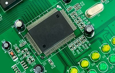
What is a High-Temperature PCB?
A high-temperature PCB is engineered with substrate materials formulated to withstand temperatures exceeding 170°C without losing critical mechanical and electrical properties. The primary characteristic defining these PCBs is the glass transition temperature (Tg) of their base materials.
Understanding Glass Transition Temperature (Tg)
Tg represents the temperature at which an amorphous polymer transitions from a hard, glassy state to a softer, more flexible state. This transition significantly affects PCB performance. When a circuit board experiences temperatures above its Tg value, it can undergo:
- Delamination between layers
- Z-axis expansion causing barrel cracking in plated through-holes
- Warping and dimensional instability affecting component alignment
- Deterioration of electrical insulation properties
Classifications of PCBs by Tg Value
PCB substrate materials are typically classified into the following categories based on their Tg values:
- Standard FR-4: Tg of 130-140°C (e.g., Isola 370HR: 135°C)
- Medium Tg: Tg of 150-160°C (e.g., Shengyi S1141: 150°C)
- High Tg: Tg of 170-180°C (e.g., Isola FR408HR: 180°C, TUC TU-872: 170°C)
- Ultra High Tg: Tg of 190-200°C+ (e.g., Isola IS410: 200°C)
- Extreme Tg: Tg exceeding 250°C (e.g., polyimide materials: 250-260°C)
The appropriate Tg value should be selected based on the maximum operating temperature, with a minimum 20-25°C safety margin above the expected peak temperature.
Why Tg Matters for PCB Performance
Electronic devices operating at temperatures exceeding 130°C require materials with higher Tg levels to maintain reliability. Using inadequate materials can lead to:
- Mechanical failure: Delamination, warping, PTH barrel cracking
- Electrical failure: Degraded insulation resistance, potential short circuits
- Component displacement: As the substrate softens, components may shift
- Reduced lifespan: Accelerated aging and degradation of the PCB
High-temperature PCBs are increasingly vital with the industry-wide transition to lead-free soldering processes, which require higher reflow temperatures (typically 245-260°C).
Features of High-Tg and High Temperature PCBs
High-Tg PCBs offer several distinctive features that provide superior performance in demanding thermal environments:
Superior Thermal Stability
- Extended operating temperature range
- Thermal cycling resistance
- Reduced thermal expansion, particularly in the z-axis
- Reflow process compatibility with lead-free soldering cycles (245-260°C)
Enhanced Mechanical Properties
- Dimensional stability at elevated temperatures
- Reduced warpage
- Higher flexural strength
- Improved via and PTH reliability
Excellent Electrical Characteristics
- Stable dielectric properties across a wide temperature range
- Lower signal loss
- Enhanced insulation resistance at high temperatures
- Superior CAF resistance
Enhanced Reliability Factors
- Moisture resistance
- Chemical resistance
- Extended service life
- Flame retardancy (UL 94 V-0 requirements)
Properties of High Tg Materials
The performance of high-Tg PCB materials is defined by several critical properties beyond just the glass transition temperature:
| Property | Standard FR-4 | High-Tg FR-4 (170°C) | High-Tg FR-4 (180°C) | Polyimide | BT Epoxy | Why It Matters |
|---|---|---|---|---|---|---|
| Glass Transition Temperature (Tg) | 130-140°C | 170-175°C | 180-190°C | 250-260°C | 180-200°C | Determines temperature at which material transitions from rigid to rubbery state |
| Decomposition Temperature (Td) | 310-320°C | 330-340°C | 340-350°C | >380°C | 350-370°C | Critical for surviving soldering processes |
| Thermal Conductivity | 0.2-0.3 W/m·K | 0.3-0.35 W/m·K | 0.35-0.4 W/m·K | 0.3-0.4 W/m·K | 0.3-0.4 W/m·K | Better heat dissipation |
| CTE (x-y plane) | 12-15 ppm/°C | 12-15 ppm/°C | 11-14 ppm/°C | 12-16 ppm/°C | 10-15 ppm/°C | Matches copper expansion to reduce stress |
| CTE (z-axis, below Tg) | 50-70 ppm/°C | 30-40 ppm/°C | 25-35 ppm/°C | 15-25 ppm/°C | 30-40 ppm/°C | Critical for PTH reliability |
| Time to Delamination (T288) | <5 min | 15-20 min | 25-30 min | >60 min | 30-40 min | Indicates resistance to delamination during soldering |
| Dielectric Constant @ 1MHz | 4.2-4.8 | 4.0-4.5 | 3.8-4.3 | 3.5-4.0 | 3.6-4.0 | Affects signal integrity |
| Loss Tangent @ 1MHz | 0.020-0.025 | 0.015-0.020 | 0.012-0.018 | 0.008-0.015 | 0.010-0.015 | Lower values reduce signal loss |
| Moisture Absorption | 0.15-0.20% | 0.10-0.15% | 0.08-0.12% | 0.20-0.25% | 0.05-0.10% | Lower values reduce risk during soldering |
| Relative Cost Factor | 1.0x | 1.2-1.4x | 1.4-1.6x | 1.8-2.2x | 1.5-1.8x | Important for material selection |
Key Material Performance Metrics
Several performance metrics are crucial when evaluating high-Tg materials:
- Time to Delamination (T260, T288, T300): Measures how long a material can withstand specific temperatures before delamination. For high-reliability applications, T288 values exceeding 15 minutes are typically preferred.
- Z-axis Expansion: Expansion perpendicular to the board surface during heating is critical for plated through-hole reliability. High-Tg materials exhibit significantly lower z-axis expansion.
- Dielectric Properties vs. Temperature: For high-frequency applications, the stability of dielectric constant (Dk) and dissipation factor (Df) across the operating temperature range is crucial.
High-Temperature PCB Applications
Automotive Electronics Applications
- Engine Control Units (ECUs)
- Temperature Environment: 105-125°C
- Material Requirements: FR-4 with Tg ≥180°C, Td >340°C
- Critical Properties: Low z-axis CTE, excellent thermal cycling resistance
- Reliability Standards: AEC-Q200 qualified materials
- Electric Vehicle Power Electronics
- Temperature Environment: Rapid thermal cycling
- Material Requirements: High-Tg FR-4 (180-200°C) or polyimide
- Critical Properties: Excellent thermal conductivity, very low moisture absorption
- Design Considerations: Heavy copper (2-4oz), thermal via arrays
- Advanced Driver Assistance Systems (ADAS)
- Temperature Environment: 70-105°C
- Material Requirements: High-Tg FR-4 with controlled dielectric properties
- Critical Properties: Low loss tangent, stable dielectric constant
- Signal Integrity Considerations: Critical for radar at 77-81 GHz
Aerospace and Defense Applications
- Avionics Systems
- Temperature Environment: Commercial aircraft: -55°C to +85°C; Military: -55°C to +125°C
- Material Requirements: Polyimide or high-Tg (180°C+) materials
- Reliability Standards: MIL-PRF-31032, MIL-PRF-55110
- Satellite Electronics
- Temperature Environment: Extreme thermal cycling from -170°C to +125°C
- Material Requirements: Polyimide or specialized ceramic substrates
- Critical Considerations: Outgassing specifications, radiation resistance
- Military Communication Equipment
- Temperature Environment: Desert conditions: sustained 70-80°C with peaks to 105°C
- Material Requirements: High-Tg FR-4 (180°C+) or polyimide
- Critical Properties: Low loss for high-frequency performance
Industrial and High-Power Electronics
- Power Conversion Equipment
- Temperature Environment: Sustained operation at 85-105°C
- Material Requirements: High-Tg FR-4 (170-180°C)
- Design Considerations: Heavy copper, thermal via farms
- Oil and Gas Exploration Equipment
- Temperature Environment: Downhole equipment: sustained 150-175°C
- Material Requirements: Polyimide or specialized formulations
- Critical Properties: Chemical resistance, extreme temperature stability
- Industrial Control Systems
- Temperature Environment: Manufacturing floors with ambient 60-80°C
- Material Requirements: High-Tg FR-4 (170°C+)
- Critical Considerations: Long-term reliability (10+ year service life)
Telecommunications and Networking
- 5G Base Station Equipment
- Temperature Environment: Outdoor installations with solar loading
- Material Requirements: High-Tg FR-4 (170-180°C)
- Critical Properties: Excellent signal integrity at high frequencies
- High-Performance Routers and Switches
- Temperature Environment: Data center equipment with high component density
- Material Requirements: High-Tg FR-4 (170-180°C)
- Design Considerations: Thermal via arrays, copper coin technology
LED Lighting and High-Power Illumination
- High-Power LED Arrays
- Temperature Environment: Junction temperatures reaching 120-150°C
- Material Requirements: Metal Core PCBs with high-Tg dielectrics
- Critical Properties: Thermal conductivity >1.0 W/m·K
- Outdoor Lighting Controllers
- Temperature Environment: Sealed enclosures with ambient temperatures 70-90°C
- Material Requirements: High-Tg FR-4 (170°C+)
- Reliability Considerations: Thermal cycling from day/night temperature variations
Heat Transfer in PCBs
For high-temperature PCBs to perform reliably, understanding heat transfer mechanisms is essential:
Radiation Heat Transfer
- Heat transfers via electromagnetic waves without requiring a medium
- Efficiency increases with temperature (proportional to T⁴)
- Highly dependent on surface properties (emissivity)
- Dark-colored solder masks increase radiative heat dissipation
Convection Heat Transfer
- Heat transfers to a fluid (air or liquid) that absorbs and moves away from the source
- Types: Natural convection (fluid moves naturally) and forced convection (mechanical means)
- Component placement should allow adequate airflow
- Orientation affects natural convection efficiency (vertical boards promote better airflow)
Conduction Heat Transfer
- Direct heat transfer through materials via physical contact
- Primary heat transfer mechanism within the PCB structure
- Efficiency directly proportional to thermal conductivity of materials
- Copper planes significantly enhance in-plane thermal conductivity
Integrated Thermal Management
In high-temperature PCB design, all three heat transfer mechanisms must work together:
- Conduction moves heat from hot components through the board structure
- Thermal vias and planes transfer heat to external surfaces
- Convection and radiation dissipate heat from external surfaces to the environment
Special Offer: Get $100 off your order!
Email sales@ourpcb.net to get started!
Material Selection for High-Temperature PCBs
High-Tg Material Selection Framework
Selecting the appropriate high-Tg material requires balancing several key parameters:
- Maximum Operating Temperature:
- 130-150°C: Standard FR-4 (Tg 140°C) may suffice with proper design
- 150-170°C: High-Tg FR-4 (Tg 170°C) recommended
- 170-200°C: Advanced High-Tg FR-4 (Tg 180-190°C) or BT epoxy
- 200°C: Polyimide or specialized ceramics
- Lead-Free Soldering Requirements:
- For reflow temperatures of 245-260°C: Minimum Tg of 170°C recommended
- Multiple reflow cycles: Materials with Td >330°C and T288 >10 minutes
- Layer Count Considerations:
- 8+ layers: Select materials with tightly controlled CTE to prevent PTH failure
- High layer count HDI: Consider materials with CTE <30 ppm/°C
- Cost Sensitivity vs. Reliability Requirements:
- High-volume, cost-sensitive: Modified high-Tg FR-4 (170°C)
- Mission-critical applications: Polyimide or specialized high reliability materials
- Commercial/Industrial balance: BT epoxy or 180°C Tg FR-4
Common High-Tg Material Types
- High-Tg FR-4
- Description: Enhanced epoxy systems with modified resin compositions
- Typical Tg Range: 170-180°C
- Advantages: Familiar processing, moderate cost increase, widely available
- Example Products: Isola FR408HR, Shengyi S1170, Panasonic R-1755M
- BT (Bismaleimide-Triazine) Epoxy
- Description: Blend of bismaleimide and triazine resins
- Typical Tg Range: 180-200°C
- Advantages: Lower CTE than FR-4, excellent dimensional stability
- Example Products: Mitsubishi MGC BT, TUC TU-862, Isola IS410
- Polyimide
- Description: Synthetic polymer with excellent thermal stability
- Typical Tg Range: 250-260°C
- Advantages: Highest temperature resistance, excellent dimensional stability
- Example Products: DuPont Kapton, Rogers 4000 series, Arlon 85N
- Ceramic-Based PCB Materials
- Description: Ceramic-filled or ceramic-core materials
- Advantages: Extremely high thermal conductivity, very high temperature resistance
- Limitations: Highest cost, specialized manufacturing required
- Example Products: Rogers 92ML, Ventec VT-4B3, AlN ceramics
Assembly Considerations for High-Temperature PCBs
Solder Alloy Options for High-Temperature Applications
| Solder Alloy | Melting Point | Application Temperature | Key Characteristics |
|---|---|---|---|
| SAC305 (Sn/Ag/Cu) | 217-220°C | Up to 175°C | Industry standard lead-free, good reliability |
| SAC405 (Sn/Ag/Cu) | 217-220°C | Up to 175°C | Higher silver content for better thermal fatigue resistance |
| Innolot | 217-220°C | Up to 175°C | Enhanced SAC alloy with additives for improved reliability |
| SN100C (Sn/Cu/Ni/Ge) | 227°C | Up to 180°C | Lower cost than SAC alloys, good thermal cycling performance |
| 90Sn/10Sb | 243-268°C | Up to 200°C | Higher temperature capability but more brittle |
| High-Temp SAC (various) | 225-240°C | Up to 200°C | Modified SAC alloys for higher temperature applications |
| 88Au/12Ge | 356°C | Up to 300°C | Specialty high-temperature alloy for extreme applications |
Best Practices for High-Temperature Assembly
- Ensure thermal profiles are precisely controlled during reflow
- Consider component temperature ratings in addition to PCB material capabilities
- Inspect solder joints thoroughly to detect potential reliability issues
- Use underfill for critical BGA components in high-temperature applications
- Consider conformal coating for additional protection in harsh environments
Modifying Existing Designs for High-Temperature Performance
For existing designs facing new thermal challenges, several modifications can enhance temperature capability:
- PCB Material Upgrades:
- Replace standard FR-4 with high-Tg materials
- Consider selective use of higher-performance materials in critical areas
- Thermal Management Enhancements:
- Add thermal vias under hot components
- Increase copper weight for better heat spreading
- Implement copper coin technology for extreme hot spots
- Add heat sinks at critical thermal locations
- Component Considerations:
- Replace components with high-temperature rated alternatives
- Redistribute high-power components to reduce thermal concentration
- Assembly Modifications:
- Switch to higher-temperature solder alloys
- Add underfill to critical components
- Apply thermally conductive adhesives at strategic locations
Why Heat Management is Necessary for Circuit Boards
Effective heat management is critical in PCB design for several fundamental reasons:
Preventing Thermal Expansion Damage
When components and PCB materials heat up, they expand at different rates, creating mechanical stress that can lead to:
- Solder joint fatigue
- Component cracking
- Plated through-hole (PTH) barrel cracking
- Board delamination
High-Tg materials significantly reduce these risks by maintaining better dimensional stability at elevated temperatures.
Preventing Electrical Performance Degradation
Heat directly impacts the electrical performance of a PCB:
- Increased resistance: Conductor resistance increases with temperature (~0.4% per °C for copper)
- Changed dielectric properties: Dielectric constant and loss tangent can shift with temperature
- Reduced insulation resistance: Inter-conductor insulation decreases at higher temperatures
- Signal integrity issues: Transmission line characteristics may change, affecting high-speed signals
Preventing Oxidation and Chemical Degradation
Elevated temperatures accelerate chemical processes that degrade PCB materials:
- Oxidation acceleration
- Dielectric material degradation
- Chemical reaction catalysis
Ensuring Component Reliability
Many electronic components have strict temperature limitations:
- Semiconductor derating: Devices must operate below specified junction temperatures
- Capacitor lifespan: Electrolytic capacitor life typically halves for every 10°C temperature increase
- Battery degradation
- Connector material limitations
Thermal Management Strategies for High-Tg PCBs
Thermal Via Implementation
- Via Density: Place thermal vias at 1.0-1.5mm pitch in arrays under heat-generating components
- Via Size: Utilize 0.3-0.5mm diameter vias for best balance between cost and performance
- Plating Thickness: Specify minimum 25μm copper plating
- Filled vs. Non-filled: Consider copper-filled vias for maximum thermal conductivity (30-40% improvement)
- Implementation Example: A typical high-power component (5W/cm²) requires approximately 25-30 thermal vias per cm²
Copper Layer Optimization
- Increased Copper Weight: Consider 2oz or heavier copper for power planes and thermal areas
- Thermal Relief Design: Optimize thermal relief connections for better heat transfer
- Copper Pours: Implement strategic copper pours connected to ground or power planes
- Solid Connections: Use solid connections (no thermal relief) for critical thermal components
External Thermal Management Integration
- Heat Sink Attachment: Design for mechanical attachment with minimal thermal interface resistance
- Thermal Interface Materials: Specify appropriate materials between PCB and cooling solutions
- Liquid Cooling Interfaces: For extreme applications, design attachment points for liquid cooling
- Forced Air Considerations: Optimize component placement for effective forced air cooling
The Coefficient of Thermal Expansion (CTE) and High-Temperature PCBs
CTE measures how much a material expands per degree of temperature change, expressed in parts per million per degree Celsius (ppm/°C).
Understanding CTE in PCB Materials
PCB materials have different CTE values in different directions:
- X-Y plane CTE: Expansion parallel to the board surface
- Z-axis CTE: Expansion perpendicular to the board surface (through thickness)
In FR-4 and similar materials, the x-y plane CTE is constrained by the woven glass reinforcement, while the z-axis CTE is dominated by the resin system.
Critical CTE Relationships in PCBs
Several key CTE relationships affect PCB reliability:
- Copper vs. Laminate CTE Mismatch
- Copper has a CTE of approximately 17 ppm/°C
- Standard FR-4 laminate has an x-y CTE of 12-16 ppm/°C (reasonable match)
- Standard FR-4 has a z-axis CTE of 50-70 ppm/°C (severe mismatch)
- High-Tg materials offer significantly lower z-axis CTE (25-40 ppm/°C)
- Component vs. PCB CTE Mismatch
- Ceramic components: 6-9 ppm/°C
- Silicon devices: 2-3 ppm/°C
- PCB laminates: 12-16 ppm/°C
- This mismatch creates stress on solder joints during thermal cycling
- Plated Through-Hole (PTH) Reliability
- Z-axis expansion directly impacts PTH reliability
- When a PCB heats up, z-axis expansion stretches and stresses the copper barrel
- High-Tg materials with lower z-axis CTE significantly improve PTH reliability
CTE Before and After Tg
A critical aspect of CTE in PCB materials is how it changes above and below Tg:
- Below Tg: Z-axis CTE for high-Tg FR-4 is typically 30-40 ppm/°C
- Above Tg: Z-axis CTE increases dramatically to 150-300 ppm/°C
This dramatic increase in expansion rate above Tg is why operating beyond Tg is extremely detrimental to reliability.
Strategies to Mitigate CTE Challenges
Several design strategies can address CTE-related challenges:
- Material Selection
- Choose materials with lower z-axis CTE for multilayer boards
- Consider materials with x-y CTE closely matching component materials
- For extreme applications, consider metal core PCBs with matched CTE
- Design Adaptations
- Use shorter aspect ratio holes where possible
- Implement stress relief features around large BGA components
- Consider staggered via designs for high layer count boards
- Assembly Process Optimization
- Optimize reflow profiles to minimize thermal stress
- Consider selective use of high-temperature underfill materials
- Implement strain-relieving component mounting techniques
Manufacturing Considerations for High-Tg PCBs
High-Tg materials present unique manufacturing challenges that require specialized processes:
Lamination Process Requirements
- Higher lamination temperatures (175-190°C vs. 150-165°C for standard FR-4)
- Longer press times (150 minutes vs. 110 minutes for standard materials)
- More precise temperature control throughout the cycle
- Specialized vacuum-assisted lamination to prevent voiding
Drilling Challenges and Solutions
- Drill bit wear increases by 30-40% compared to standard FR-4
- Recommended drill speeds are reduced by 10-15%
- More frequent drill bit replacement is necessary (every 1000-1500 hits vs. 2000+ for standard FR-4)
- Drill bit selection, peck drilling, and optimized parameters for specific material hardness
Copper Plating Considerations
- Enhanced cleaning and preparation processes to ensure proper adhesion
- Modified plating chemistry for improved throwing power in high aspect ratio holes
- Stress relief annealing may be required for thick copper deposits
- Tighter monitoring of plating thickness uniformity
Testing and Quality Assurance
- TMA (Thermomechanical Analysis) to verify actual Tg values
- T260/T288/T300 tests to measure time to delamination
- Thermal stress testing with multiple reflow simulations
- Microsectioning to verify inner layer registration and PTH quality
The manufacturing cost impact for high-Tg materials is typically 15-25% higher than standard FR-4, due to increased material costs, longer processing times, and higher tooling consumption.
Design Considerations for High-Temperature PCB Applications
Thermal Management Design
- Thermal Mapping and Analysis
- Use thermal simulation tools to identify potential hotspots
- Consider both steady-state and transient thermal conditions
- Model actual operating environments, including ambient conditions
- Heat Spreading Techniques
- Implement continuous ground and power planes for enhanced thermal conductivity
- Use thermal vias strategically under hot components
- Consider embedded heat pipes or metal cores for extreme applications
- Optimize copper weights and distribution for heat spreading
- Thermal Isolation Strategies
- Isolate temperature-sensitive components from heat sources
- Consider slot cuts to limit heat propagation to sensitive areas
- Implement zone-based thermal management approaches
Component Selection and Placement
- Temperature Rating Requirements
- Ensure all components are rated for the anticipated operating temperature
- Apply appropriate derating factors for long-term reliability
- Verify temperature ratings for passive components (capacitors often limiting)
- Strategic Component Placement
- Position heat-generating components with adequate spacing
- Avoid clustering hot components together
- Place sensitive components away from heat sources
- Consider airflow paths when positioning components
- Package Type Considerations
- Prefer packages with better thermal performance
- Consider thermal resistance when selecting equivalent components
- Evaluate solder joint reliability under thermal cycling
Advanced Layout Techniques
- Thermal Relief Design
- Optimize thermal relief connections for better heat dissipation
- Consider solid connections to planes for critical thermal components
- Balance thermal performance with assembly requirements
- Via Design Strategies
- Implement via farms under hot components
- Consider filled thermal vias for maximum thermal conductivity
- Size vias appropriately for current-carrying capacity and thermal performance
- Copper Distribution
- Balance copper distribution to prevent warping at high temperatures
- Consider heavier copper weights for power distribution and thermal planes
Reliability Enhancement Techniques
- Teardrop Pad Reinforcement
- Add teardrop reinforcement to pads and vias
- Enhances reliability during thermal cycling
- Stress Relief Features
- Add stress relief cutouts near large components
- Use curved traces instead of right angles in critical areas
- Implement stress relief loops for rigid-flex connections
- Enhanced Surface Finishes
- Select surface finishes appropriate for high-temperature exposure
- Consider ENIG or hard gold for critical connections
- Verify compatibility with multiple reflow cycles
High-Tg & High Temperature PCB: FAQ
What is the difference between Tg and Td in PCB materials?
- Glass Transition Temperature (Tg) is when material transitions from rigid to softer state. Above Tg, the material experiences increased CTE, reduced mechanical strength, and decreased dimensional stability.
- Decomposition Temperature (Td) is when material begins to chemically break down (typically measured at 5% mass loss). Always higher than Tg (typically above 300°C).
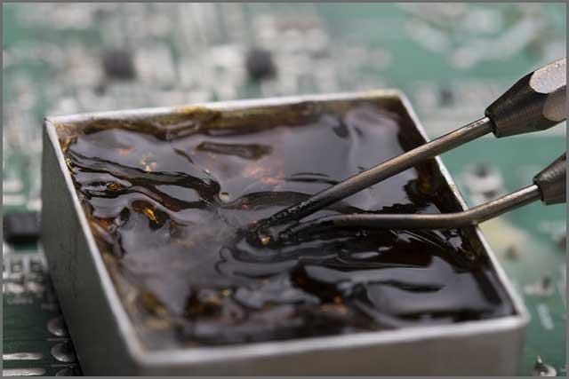
What is high-heat solder called in electrical applications?
Common high-temperature solder alloys include:
- SAC305 (Sn96.5/Ag3.0/Cu0.5): Industry standard lead-free (217-220°C melting point)
- SAC405: Higher silver content version with better thermal fatigue resistance
- SN100C (Sn/Cu/Ni/Ge): Nickel and germanium modified tin-copper alloy (227°C)
- Innolot: Enhanced SAC alloy with additional elements for improved performance
- Tin-Antimony (Sn90/Sb10): 243-268°C melting range for higher temperature applications
- Gold-Based Alloys: For extreme applications (Au88/Ge12, melting point 356°C)
What is the Tg value of FR4 PCB and how do different grades compare?
- Standard FR-4: Typically 130-140°C
- Medium Tg FR-4: 150-160°C
- High-Tg FR-4: 170-180°C
- Ultra High-Tg FR-4: 190-200°C+
What is the maximum temperature for FR4?
Short-Term Processing Temperature Limits:
- Standard FR-4 (Tg 130-140°C): Up to 230-240°C briefly
- High-Tg FR-4 (Tg 170-180°C): Can handle lead-free soldering (245-260°C)
- Ultra High-Tg FR-4 (Tg 190-200°C+): Can withstand multiple lead-free reflow cycles
Continuous Operating Temperature Limits:
- Standard FR-4: Up to 105-115°C
- High-Tg FR-4: Up to 145-155°C
- Ultra High-Tg FR-4: Up to 170-175°C
The industry standard is to maintain at least a 20-25°C margin below Tg for reliable operation.
What are the materials for high thermal conductivity PCB?
- Metal Core PCBs (MCPCBs)
- Aluminum Core: 1.0-2.0 W/m·K thermal conductivity, good cost-performance
- Copper Core: 3.0-4.0 W/m·K thermal conductivity, higher cost
- Ceramic-Based Substrates
- Aluminum Nitride (AlN): 170-200 W/m·K
- Aluminum Oxide (Al₂O₃): 20-30 W/m·K
- Silicon Nitride: Excellent thermal with superior mechanical properties
- Thermally Enhanced FR-4
- Ceramic-Filled FR-4: 0.4-1.0 W/m·K
- Advanced Thermal Laminates
- T-lam, Ventec VT-4B3
- Hybrid Solutions
- Embedded Metal Coins, Partial Metal Core
How does high Tg affect PCB manufacturing processes?
High-Tg materials significantly impact manufacturing:
- Lamination: Longer press cycles, higher temperatures, more precise control
- Drilling: Increased material hardness accelerates bit wear, requires slower speeds
- Copper Plating: Enhanced cleaning, modified chemistry for improved throwing power
- Impedance Control: Different dielectric constants require adjusted design rules
- Testing: Additional thermal testing to verify material properties
These adaptations result in 15-25% higher manufacturing costs compared to standard FR-4.
What are common failure modes in high-temperature PCB applications?
- Delamination: Separation between layers due to excessive temperature
- PTH Failures: Barrel cracks from z-axis expansion during thermal cycling
- Pad Cratering: Cracking beneath pads due to CTE mismatch
- Conductive Anodic Filament (CAF) Formation: Copper migration along glass fibers
- Solder Joint Fatigue: Cracked joints from repeated thermal cycling
- Trace Degradation: Increased resistance and physical damage to conductors
- Dielectric Breakdown: Heat accelerating insulation degradation
- Component Failures: Due to inadequate heat dissipation leading to overheating and premature failure
Back to Top: High-TG & High Temperature PCB: FR4 Material & Price List
Special Offer: Get $100 off your order!
Email sales@ourpcb.net to get started!