If you are into designing RF amplifier, you need to know how to select the perfect RF amplifier.
Considering that this is a simple circuit, you don’t have to do it by yourself.
But it is good to know the constructs you need to design an RF amplifier.
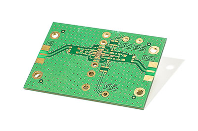
Caption: RF amplifier PCB isolated on the white background
Anytime you can face a problem with the components which can deter your project.
If you are looking for the right amplifier, here are all the features you need to know.
Contents
- Design Steps
- Steps 1 - Determine 5 Design Stages of The RF Amplifier
- Steps 2 - Choose RF Amplifier Class as Per the Application
- Steps 3 - Gain Selection Process for RF Amplifier
- Steps 4 - Buffer Design for Maintaining Signal
- Steps 5 - Driver Design to Drive Low-Impedance Loads
- Solid-State RF Amplifier Example
- RF Amplifier Technical Specifications
- Frequency range
- Gain
- Input/output impedance
- Noise figure
- Output power
- Third-order intercept and 1-dB compression points
- Solid-state technology
- DC power
- Packaging
- Temperature
- Low Noise Amplifier - RF Amplifier Application
- Conclusion
Design Steps
Steps 1 - Determine 5 Design Stages of The RF Amplifier
- Input Matching network: The impedance line connects with the amplifier with a 50-ohm input.
- Amplifiers one or in stages: It depends on your requirements. Usually, it relates to the circuit gain or if the device calls for single or multiple microphones.
- Biasing network: The biasing system supplies the device with voltage or bias.
- Accessories network: The amplifier needs several features and methods for the device to remain stable.
- Output matching network: The impedance line connects with the amplifier with a 50-ohm output.
Steps 2 - Choose RF Amplifier Class as Per the Application
- Class A - The q point of this class is 0.5. The conduction angle for the same is 360 degrees of 2pi.
- Class B - The q point of this class is zero, so when the current reaches near zero, that is the biased point. The conduction angle is 180 degrees or pi.
- Class AB - The q point of the class lies somewhere above 0 and below 0.5, so the conduction angle of the course is between pi and 2pi.
- Class C – The q point of this device is less than 0, and the conduction angle falls between 0 and pi.
Steps 3 - Gain Selection Process for RF Amplifier
The purpose of gain selection is for when the RF signal amplitude is minimal and is not very useful anywhere in the circuit. It should increase to bring up the signal to noise ratio, so it does not decay when the message goes through the course.
The main task of the gain amplifier is to improve the signal quality by eliminating extra noise. They are ideal for handling shallow signals from the antenna.
Not all RF amplifiers will have varying gain; some of them provide a fixed gain value, which is controlled by an external resistor. The last type of RF amplifier is known as a variable gain amplifier.
It allows you to determine the gain, from a wide range. The variable gain amplifier also controlled by an external resistor that can be digitally programmed or a voltage control method by the analogue operation.
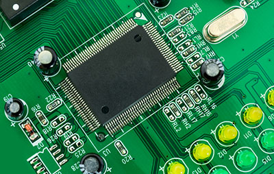
Caption: RF Amplifier Design -- Electronic Components
Steps 4 - Buffer Design for Maintaining Signal
Sometimes the circuit load can change. The buffer design ensures that the signal or circuit does not change in amplitude or structure. The second purpose of the buffer designer is to add a load to the course that has a higher amount than the circuit can handle.
If you need to control the output impedance of the circuit, the circuit will provide a signal to the input impedance to the power into the amplifying course.
When you are selecting the buffer design, the most crucial factor you need to look for in the span of the loads it can handle while keeping the signal steady and pure.
Steps 5 - Driver Design to Drive Low-Impedance Loads
The primary purpose of the driver when you design an RF amplifier is that it can set the low impedance load between 50 to 70 ohms. Since they can deliver a power increase for driving a charge, they are also considered power amplifiers.
Some drivers deliver gain boost by design, whereas some others focus on providing a fixed unity gain. These drivers are usually installed externally to the cables and interfaces. It means they can tolerate small circuits to the ground and power rails carrying DC. The main component is its source vs sink rating. Next is short circuits and withstanding capability of misconnection.
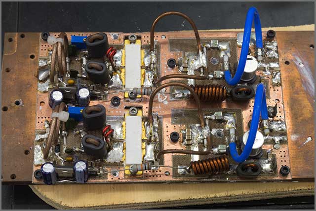
Caption: RF amplifier design circuit
Special Offer: Get $100 off your order!
Email [email protected] to get started!
Solid-State RF Amplifier Example
The solid-state RF amplifier has three stages - intermediate, input, and output. The section that handles the power supply to the device should control the appropriate voltage level. The heatsink of the device needs to be able to handle the generated heat and cool it down as necessary.
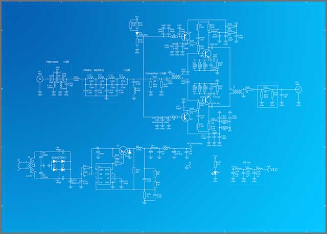
Caption: RF amplifier electronic circuit schematic
RF Amplifier Technical Specifications
To design an RF amplifier, you need to know about the following technical specifications.
Frequency range
The frequency range should be fit for any device so that it can use for all kinds of applications. Usually, the span of the frequency is between 500 MHz to 5 GHz.
Gain
The gain is measured by what kind of use you have for the device, but the universally accepted value is between 10 to 20 dB. You should have an extensive range of frequency for this gain. Ideally, any amplifier which has a flat increase of around 100 MHz, lower than about 0.2 dB, would work.
Input/output impedance
As mentioned before, this set to 50 ohms for both input and output impedance.
Noise figure
The higher the device frequency gets, the higher the noise. It will seriously hinder the performance of the amplifier, so the noise figure is an important aspect you should seek. The signal-to-noise ratio should be similar to the signal-to-noise ratio of the amplifier input and an amplifier output, in dB. Ideally, you should have something in the 2dB range, but anything below 3 dB would work perfectly fine.
Output power
Consider the maximum possible level when working with a 50-ohm load, with the supply voltage being at the highest point. The output power measured by dBm and should have an ideal range between 12 to 28 dBm.
Third-order intercept and 1-dB compression points
These points are indicators that the amplifier you are using for boosting the power is efficient. Most devices would use some kind of broadband modulation scheme, including decent linearity. It will keep the data retention at an optimum level and ensure the broadband usage is at best.
Solid-state technology
If you are using devices operating at very high frequency, then the amplifiers could be made of CMOS silicon. But usually, they are build out of gallium arsenide or silicon germanium, and the latter is a little more dependable than the previous. These compounds are very high performing than ordinary silicon when you are working with very high frequencies.
DC power
The supply voltage for most RF amplifiers will be between 1.8 and 6 V. The number of current channels to the device depends on the level of current provided and the type of power generated, which ranges from 20 to 100 mA.
Considering that the amplifier should come with a standby mode, the current level should not fall below a certain level to keep the device going.
Packaging
The size of the package is usually tiny and falls within 4 mm square to 25 mm square.
Temperature
The tolerated range is between – 40 degrees C and + 105 degrees C.
Low Noise Amplifier - RF Amplifier Application
The purpose of the RF amplifier is not simple to define. It has multiple roles. It can work as a power amplifier when it is sending a signal gain before transmission occurs by connecting with the transmitting antenna. Sometimes, it is connected after the signal is received. It is known as a low noise amplifier. It can get a message without boosting up the noise.
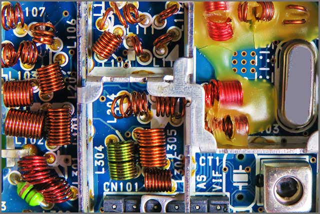
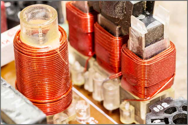
Caption: an electronic radio frequency module
Conclusion
When you design an RF amplifier, the specifications will majorly rely on the intended application. Your device should have the right gain and should work with the correct frequency to ensure the device operates on a stable level.
Most RF amplifiers have the mentioned parameters in stock. For unique designs, some settings need more strength. Like, if you need strong signals, then use a high TOIP amplifier.
Either way, the RF amplifier is not a single device but refers to an extensive range of accessories. It has a crucial role in the signal change, beginning with LNA, and working as a buffer, matching signal, and much more. Understanding all the parameters gives you the flexibility of design, and we hope this post helped make you the right choice.
Special Offer: Get $100 off your order!
Email [email protected] to get started!