RF amplifier design has an essential task. They amplify your input signal to improve bandwidth, coverage, and efficiency. Without them, you will have it difficult to manage your RF signals.
We will present the six most important points to consider while beginning your RF project. But before that, we will take a look at the typical applications of RF amplifiers.
So let’s move ahead without any more delays!
Alt – Radio frequency amplifier
Contents
- 1. Application Areas of RF Amplifier Design
- 1.1. 4G FDD and TDD base stations
- 1.2. 5G Base Stations
- 1.3. Wireless Repeaters
- 1.4. Distributed Antenna Systems (DAS)
- 1.5. Infrastructure Point-to-Point Radios
- 1.6. Public Safety Wireless Equipment
- 1.7. Military Radios
- 1.8. Test and Measurement Equipment
- 2. What Are the Functions of an Amplifier? Mention the Different Types of RF Amplifiers?
- 2.1 The RF Amplifier has three main functions. Almost all its applications use these three.
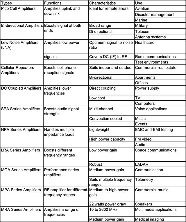
- 2.2 RF amplifiers can be of many types based on their use and design. Here is a table for your reference-
- 3. Factors to Consider for Choosing a General Purpose Linear RF Amplifier
- 3.1 Frequency Range
- 3.2 Gain
- 3.3 Input /Output Impedance
- 3.4 Noise Figure
- 3.5 Output Power
- 3.6 Third-Order Intercept and 1-dB Compression Points
- 3.7 Solid-State Technology
- 3.8 DC Power
- 3.9 Packaging
- 3.10 Temperature
- 4. What Does a Neutralizing Circuit Do in an RF Amplifier?
- 5. How to Calculate RF Signal Through Amplifier?
- Step 1
- Step 2
- Step 3
- 6. How to Test an RF Amplifier?
- Using detectors:
- Spectrum measurement:
- Conclusion
1. Application Areas of RF Amplifier Design
As we said, RF amplifiers have a wide range of applications. You can use them for mobile internet, satellite communication, and military, wireless communication. Whenever you need to magnify your radio frequencies, think of an RF amplifier.
Here are some of the most common applications-
1.1. 4G FDD and TDD base stations
Definition
4G FDD (Frequency Division Duplex) is one, and the other is TDD (Time Division Duplex). These are the two standards of LTE 4G technology. We use technology every day on our mobiles while accessing online services.
Design specification
FDD utilizes a paired spectrum derived from 3G; TDD uses an unpaired spectrum from TD-SCDMA. The amplifiers work across multiple modes and bands for higher reliability and amplification.
The FDD method deploys two different carrier radio frequencies for transmission and receiving. Being a full-duplex method, both the functions can occur at the same time. The two bandwidths were separated by an offset frequency(Guard band). In TDD, both transmission and receiving occur through the same channel. TDD is cheaper due to the absence of a diplexer. Plus, a user can regulate the download and upload speeds in TDD.
Design case
To send and receive signals at the same time for enhanced communication stations. The expected benefits include a better talk with improved broadcast and viewing times. These amplifiers make the 4G technology more robust with exceptional signal strength.
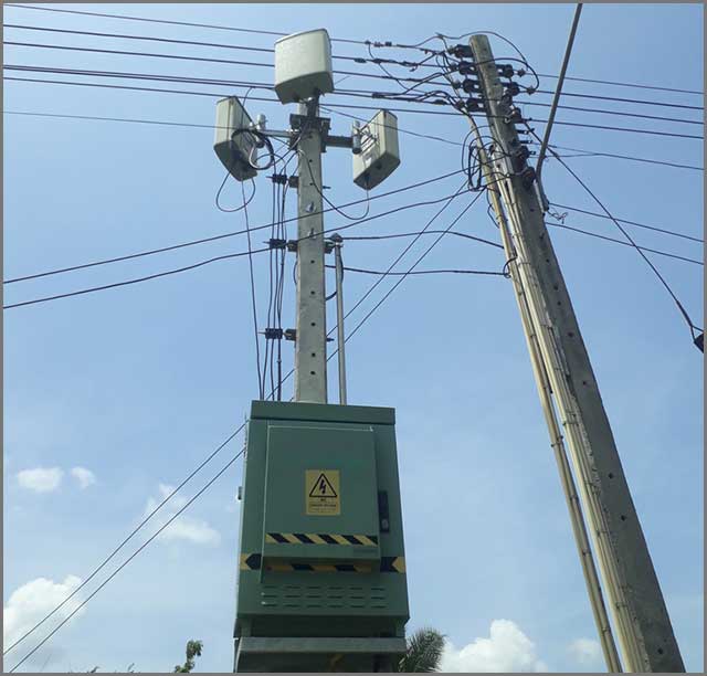
1.2. 5G Base Stations

Alt- 5G base station tower
Definition
Base stations for the 5G spectrum mostly use these for mobile connectivity. 5G is an advanced and high-speed network that is becoming popular across the world.
Design specification
It needs thousands of 5G towers and distributed antenna systems. The amplifiers work for 5G technologies like IoT/LTE-A/5G. They also depend on high integration levels for keeping costs low.
The 5G bandwidth spectrum consists of frequencies ranging from the 24 GHz to 95 GHz. Now, there are two ranges here. The sub6 GHz range (24GHz-39 GHz) and the millimeter-band spectrum (30Hz-300Hz) are popular. These are in use for high-speed data transmission, in addition to MIMO technology.
Design case
To facilitate 5G connectivity and communication. The high download speeds of 5G can tolerate very low latencies. The amplifiers improve bandwidth and provide high-power efficiency.
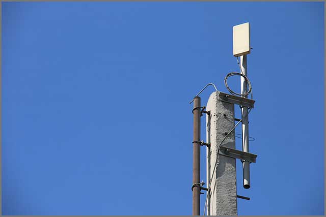
1.3. Wireless Repeaters
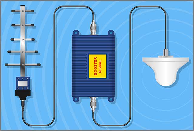
Alt Title- Wireless RF Receiver Signal Booster
Definition
Wireless repeaters are wireless range extenders and work for devices like WiFi routers. They are great at expanding the coverage of wireless signals.
Design specification
Comes with receiver, amplifier, and signal transmitter to extend coverage. Many speakers can even boost WiFi signals by regenerating signals. However, a repeater generally provides a low power output. You also use them mostly in static or stationary environments.
Repeaters and extenders take full advantage of duplex and half-duplex bi-directional amplifiers. Bi-directional amplifiers can transmit as well as receive RF signals.
Design case
Widens the network coverage of wireless signals like WiFi. Enables people in a large area to get the RF signals. Regenerating signals can also reduce issues like noise in the message. So, it can improve signal quality.
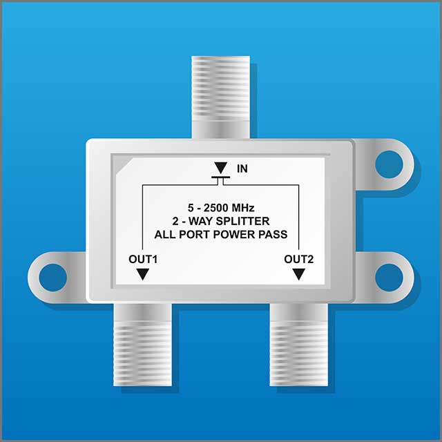
1.4. Distributed Antenna Systems (DAS)
Alt- DAS
Definition
DAS is a network of antenna nodes. The spatially separate nodes connect to a common terminal. The terminal medium provides wireless services in a specified geographical area.
Design specifications
A DAS uses analog-to-digital conversion to turn RF transmission to digital signals. The amplifiers are bi-directional and can boost signals of varying frequencies. They can even help messages reach in areas obstructed by mobile phone towers.
Passive splitters and feeders are necessary for implementing DAS; Active repeater amplifiers can overcome feeder losses. DAS is in use to spread the indoor WiFi area for commercial purposes.
Design case
Use for wireless communication by police, emergency services, and even WiFi. Also useful for hospitals, airports, commercial buildings, and tunnels. Ideal for accessing services in areas otherwise not covered by signals.
1.5. Infrastructure Point-to-Point Radios
 Alt Text- P2PTechnology
Definition
The point-to-point(P2P) radio is a wireless topology to connect two sources to form a network. It is the connection between two nodes or endpoints.
Design specifications
It has one of the most straightforward network architectures. The P2P wireless topology can function over small and large distances, and a short range-link can connect two locations a few hundred meters apart. All you need to do is use a wireless radio. The deciding factors include many things. For instance, you see the height of the Ethernet radio device. Then, you know the frequency, output power, and possible environmental interference.
The circuits come with point-to-point configuration to enable transmission and broadcast. The amplifiers can relay signals in a bidirectional manner. The systems are ideal for developing high-performance wireless infrastructure.
Deploying the link in a clear line of sight is necessary for a stable network above 2.4 GHz. A reliable P2P wireless connection is possible in 900 MHz or the 400 MHz band at NLOS (Near Line of Sight).
Design case
You see these for two-point wireless connectivity using radio frequencies. Useful for telecom, wireless internet, and base stations. Strengthens and amplifies signals for better performance.
1.6. Public Safety Wireless Equipment
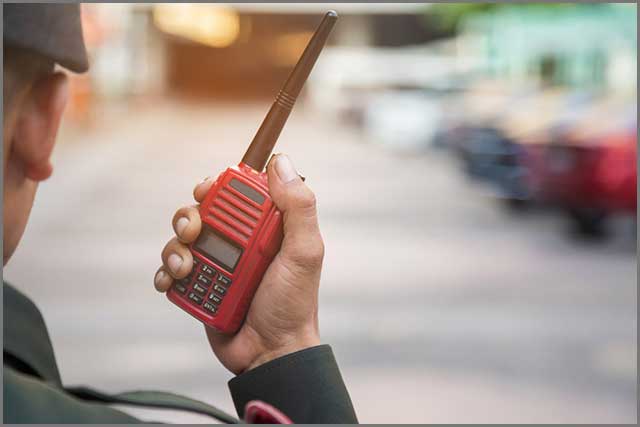 Alt text- Secure Communication
Definition
Public safety wireless equipment is a dedicated communication infrastructure for public safety purposes.
Design specifications
The architecture uses systems like TETRAPOL for voice and data communication. Amplifier specifications differ based on the nature of the wireless system in use. However, the amplifiers are mostly bidirectional. They also help extend coverage and connect more emergency personnel on the network.
Design case
Police, fire department, and governments use it for securing citizens. The technology operates through walkie-talkies and similar tools. Modern safety equipment that works over the internet may also use amplifiers.
1.7. Military Radios
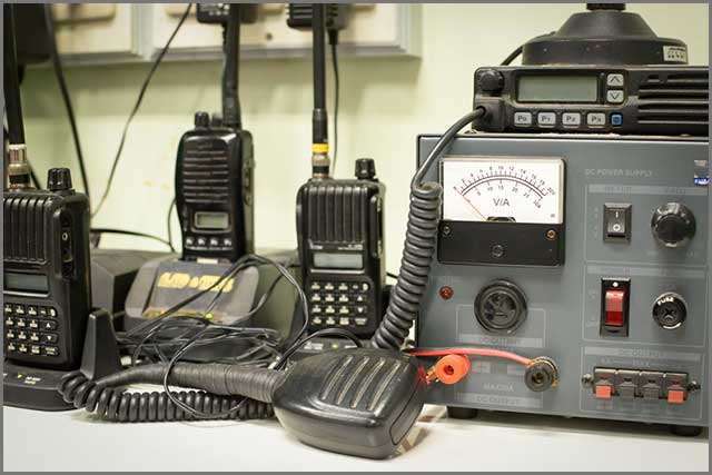 Alt text- Military Radio Communication Equipment
Definition
Military radios are specially-designed communication devices for defense communication. Army personnel uses the system during patrolling and wars.
Design specifications
You can see handheld radios, tactical radios, and rebroadcast stations. Amplifiers include multi-band tactical RF amplifiers or booster amplifiers.
High-rel amplifiers, LNAs, and bidirectional amplifiers being the most common. Airplanes use a dedicated bandwidth of 225-400 MHz. Known as the airband, it is also common in civil aviation. Among land troopers, RF amplifiers in the 30-512 MHz bandwidth frequency is standard.
Design case
The military uses RF technology for communication during warfare and emergencies. Works efficiently, even in areas with severe disruptions for maintaining uninterrupted connectivity.
1.8. Test and Measurement Equipment
 Alt Text- EM compatibility test
Definition
Test and measuring equipment refers to a range of RF components and equipment. You can use them for testing and measuring signals and voltages.
Design specifications
Designs vary according to the equipment, such as handheld radios. Most amplifiers have input buffers that don’t need you to match impedance. As a result, you can use them with a range of testing and measurement devices.
Design case
The design suits the test of electromagnetic noise of devices. They can determine the efficiency of various tools and machines. They can also help in performance verification.
2. What Are the Functions of an Amplifier? Mention the Different Types of RF Amplifiers?
RF amplifiers work at low voltage (often lesser than 1 Volt). Wireless RF signals usually lie within the 20 kHz to 300 GHz frequency range. The range is the human upper auditory threshold. It is also the starting point for infrared frequencies.
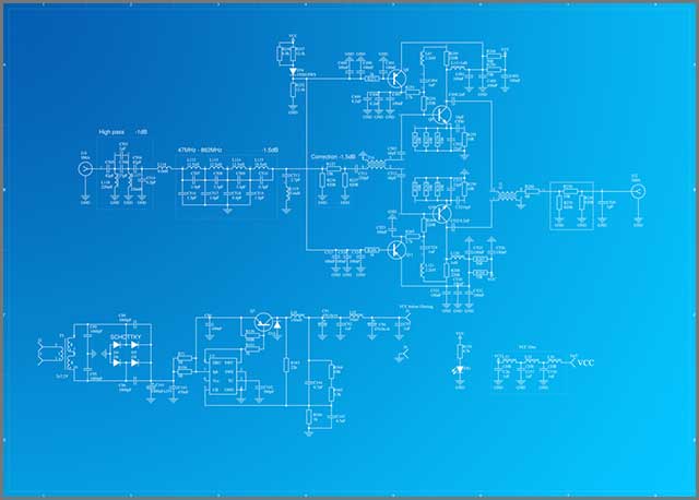 Alt Text- Schematics for RF Amplifier
2.1 The RF Amplifier has three main functions. Almost all its applications use these three.
Amplification Gain
One of the RF Amplifier's main functions is to increase the strength when the input amplitude is too low.
The Signal-to-Noise Ratio(SNR), a key-value in RF amplifier components, must not have a value less than 1.1. Reduced SNR values are where the gain comes in. The amplitude needs to match the required input range for components such as the A/D converter. Antennas emit RF signals having a potential voltage. The voltage varies within the microvolt to the millivolt range.
Gain amplifiers strengthen the input signal frequency but avoiding noise or distortion. LNAs are compatible and functional with low-signal levels from the antenna. Some of the LNA (low noise amplifiers) designs permit fixed-gain amplification (2x, 4x, 8x, 16x, 10x, or 100x). VGAs (variable gain amplifiers) provide users with better control.
They can fine-tune the gain as per requirements. In VGA, added components include voltage control options like an external resistor. Analog controls between 0 to 1 v are also not uncommon.
Buffer Amplification
Buffer is useful in maintaining a uniform signal shape and amplitude (especially the ever-increasing signal load). Buffer amplifier prevents signal distortion or fidelity changes due to impedance. Match the output circuit impedance from the complicated conjugate method using buffer amplifiers. It is a popular method.
Driver Amplification
A driver functions as a current source-and-sink and for low impedance loads. They provide a power boost to drive the antenna in the form of current/voltage. Hence RF driver amplifiers are also known as RF power amplifiers.
Depending upon their configuration, RF drivers can provide both gain and fixed-unity gain. Other innovative applications include user-operated interfaces and DC operated power rails. The parameters to look out for are the source/sink ratings. Different ratings related to time and voltage are also necessary.
A considerable number of RF amplifier circuit components are available in the market today. To prevent misuse and mismatch, know the exact details of your circuit components. Opt for experienced and reputed manufacturers for quality and assurance.
2.2 RF amplifiers can be of many types based on their use and design. Here is a table for your reference-
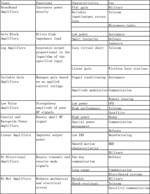
1) Broadband Amplifiers:
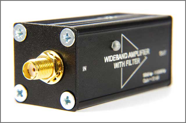 Alt Text- Wideband Amplifiers
Also known as wideband amplifiers, these amplifiers provide gain throughout a broad bandwidth. Their design ensures that they maintain minimal noise or signal distortion. Broadband amplifiers are standard in receiver circuitry and at the antenna front.
Impedance is the opposition to the current flow by the circuit on applying a load voltage. It is difficult to estimate the impedance transformations over a broad bandwidth. It results in the everyday use of 50 Ω as the output load.
Pout ≤ (Vbr - VK )2/8 Z0
Where Pout= Transistor Output Power
Vbr = Breakdown Voltage
VK= Knee Voltage.
2) Gain Block Amplifiers
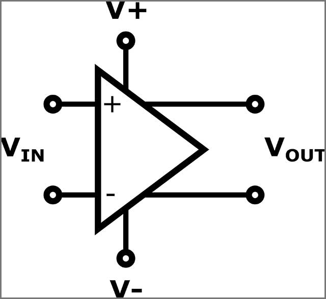 Alt Text- Schematic of Generic Op-Amp
Gain blocks are like broadband amplifiers. But, they fail to provide low noise levels comparable to the broadband amplifiers. Instead, they have higher gain levels and are prevalent in IF, RF, and microwave transmitters.
Gain blocks can deliver a power level ranging from 5 dBm to 1W through many bandwidths. They are suitable for use in either a narrowband or broadband. But, this depends upon their design purpose.
Gain block amplifiers are widespread in industries, defense, aerospace, and wireless infrastructure.
3) Log Amplifiers
An output voltage proportional to the natural log of the input voltage.
The gain curve in log amplifiers is useful for performing distinct operational functions.
The equations for the log amp uses the virtual short concept. The voltage at inverting input terminals remains 0 V. The 3 step process involves:
The nodal equation at input terminal:
(0-Vi)/R1 + If ⇒ If = Vi/R1
The equation for forward-bias current in a diode:
If = Is e
Applying KVL and natural log on the 2nd equation
V0= -nVTln ()
Here,
IS= Diode saturation Current
Vf= Voltage drop in forward-bias
VT= Equivalent thermal Voltage
VI= Input Voltage
4) Variable Gain Amplifiers (Linear-to-Logarithmic Converters)
The main advantage of variable gain amplifiers is the ability to control gain. At times, the benefit is programmable and can even yield desired results. VGC(Variable Gain Circuits, also known as variable attenuators) can achieve this control. Abbreviated as VCA, they often are part of a closed-loop control circuit. This circuit maintains a consistent signal power level.
The prime application of VCAs is in the music studios and audio production. They are essential for sound level compression, amplitude modulation, and synthesizers. VCAs also find their uses in many other industries.
5) Low Noise Amplifiers
The low noise amplifier (LNA) can amplify low-power signals and reduce the additional noise familiar to traditional speakers. Circuit designers achieve this using specialized components and circuit topologies. Equal focus is necessary for power gain and matching impedance.
Familiar places of LNA use include radio communication systems. Testing equipment- both electronic and medical use LNAs. An average LNA can provide a power gain of 20 decibels. The signal-to-noise ratio may decrease by less than a factor of two(3dB noise figure). While LNAs deal with weak signals, the impact of reliable signals is also essential. High-power signs combined with the high-gain of LNAs are responsible for intermodulation distortion.
6) Coaxial and Waveguide Power Amplifiers
Placed at the front of RF transmitters, these PAs convert tiny communication signals. The signal is then amplified and transmitted through a high powered antenna. A power amplifier keeps uninterrupted high gain levels on a message. Constructing a power amplifier is challenging- considering its varied uses. A distinct feature of power amplifiers is their protective circuitry.
The RF signal undergoes preamplification through current/voltage amplifiers. The modified message is then sent through the power amplifier for amplification. Many speakers need the least threshold to function.
7) Linear Amplifier
The output of the linear amplifier has a direct relationship with the input signal. It can provide more power into the load—the immediate output results in zero issues of distortion- harmonics or intermodulation. Linear amplifiers are standard in audio and testing equipment, as well as amateur radio.
A perfectly linear replication of the original input signal is hypothetical. Components like transistors or vacuum tubes obey non-linear power laws. They also rely on circuit techniques. The class division depends upon the efficiency and the bias nature(+ve or -ve)of linear amplifiers. Classes include Class A, Class B, Class AB1, Class AB2, and Class C. A rise in efficiency indicates non-linear.
8) Bi-Directional Amplifiers
Bi-directional amplifiers can function both as a receiver and a transmitter. A typical example locates a wireless signal, amplifies it. The amplified signal is then broadcast throughout the entire area. Bi-directional amplifiers are significant components of signal range extension devices. There are two categories of bi-directional amplifiers- full-duplex and half-duplex.
Both can perform receiving as signal transmission as well as signal receiving. But unlike the full-duplex, half-duplex amplifiers can not perform both at once.
9) Hi-Rel Amplifiers
The “Hi-Rel” stands for high reliability. These components have a reliable and consistent performance throughout their lifetime. The parts also have a tested lower rate of failure. Compared to the other amps- they are better performers in reliability standard procedures. Hi-Rel Amplifiers can function well even under extreme conditions.
High-rel amplifiers are conventional in automotive industries, military defense, aerospace, and medical research. Reliability and precision are critical in these segments. Clearing international test standards is thus very important for any high-rel amplifier.
10) Industrial Amplifiers
Industrial amplifiers find use in commercial applications. Businesses and manufacturers use it to provide goods and services.
The specific PCB design allows for different circuitry. Thus, different RF amplifier circuits can find applications in diverse fields.
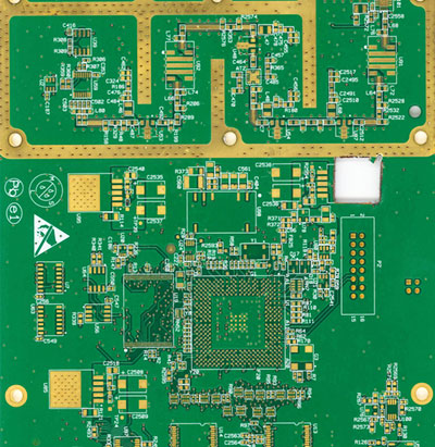
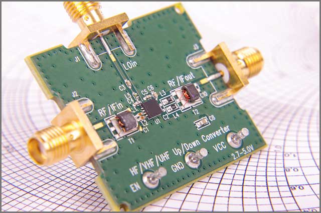
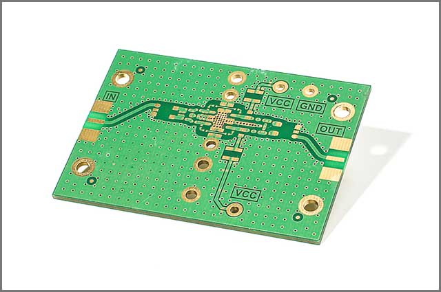 Alt- Amplifier PCB
Special Offer: Get $100 off your order!
Email [email protected] to get started!
3. Factors to Consider for Choosing a General Purpose Linear RF Amplifier
3.1 Frequency Range
RF amplifiers remain in the range of 20KHz to 300 GHz. A good design can cover the field for most applications.
3.2 Gain
The power gain of the amplifier is a measurement of the amplification of the input power. The increase varies with different speakers. Every application needs a distinct benefit.
In RF amplification, the gain is the ratio of output to input. You express it in dB.
Amplifier Gain
Voltage Gain (AV) = =
Current Gain (Ai) = =
Power Amplifier Gain(AP) =
3.3 Input /Output Impedance
A simple RF amplifier uses a Capacitor Inductor network or LC network. The L network helps in impedance matching, but It is important to determine the input and output impedance. We generally keep the impedance to 50 Ω.
You denote it as Zin and Zout, and Zin depends upon source feed to the amplifier. Zout depends upon load impedance RL across the terminals.
3.4 Noise Figure
The amplifier receives unwanted background signals and processes them. It gives rise to the noise figure.
By definition, the noise figure is the noise factor expressed in decibels.
SNR compares the signal power to the amount of noise in the background. A value higher than 1.1 indicates a higher signal compared to sound.
If there is no noise produced, the RF amplifier will have a zero noise figure. In practical cases, you should have a noise figure below 3dB.
The correct PCB design will assist in obtaining the desired output.
3.5 Output Power
The output power of an RF transmitter is the actual amount of energy provided as output. You denote it in watts. The transmitter amplifies the input power many times. Then you get the final output power. The output power is merely equal to the input power, plus the gain.
3.6 Third-Order Intercept and 1-dB Compression Points
Linearity is an essential factor in specifying the RC amplifier. Third Order Intercept (IP3) is a measure of linearity of the RF amplifier. The linearity decides the amount of data retention and the best use of the bandwidth. They are essential to determine the efficiency of the speaker.
As you increase the input power, the output power increases. After a certain point, the curve flattens. It indicates distortion.
The third-order intercept measures how much signal the amplifier can process. It indicates the limit when distortions or interference occurs.
3.7 Solid-State Technology
Most RF amplifiers come in the structure of stable states. CMOS is the most common material for the speaker; Silicon-Germanium is the most reliable material in use for RF amplifiers.
 Alt – Frequency range for amplifier
3.8 DC Power
The output power is the total amplified power at the output terminal. It depends on the impedance of the circuit and is an essential parameter in the transistor's design.
1.8- to 6-V is the full operating range of standard IC RF amplifiers. The voltage at the input end doesn’t stay the same all the time. So, the output power can also vary. The output power can range from 20 mA to more than 100 mA.
The current reduces by a few milliamps if your amplifier works on a standby mode.
3.9 Packaging
Most RF amplifiers have to make good use of available space. They are usually tiny packages and take advantage of the surface mount technology or SMT. They use sophisticated equipment for the purpose.
Engineers also commonly use DFN and SOT-89. You can find sizes like 2× 2 mm, up to 5 × 5 mm.
RF packaging uses microchips integrated with the printed circuit boards, thereby reducing space and improving efficiency. It is essential in the defense industry and low volume aerospace.
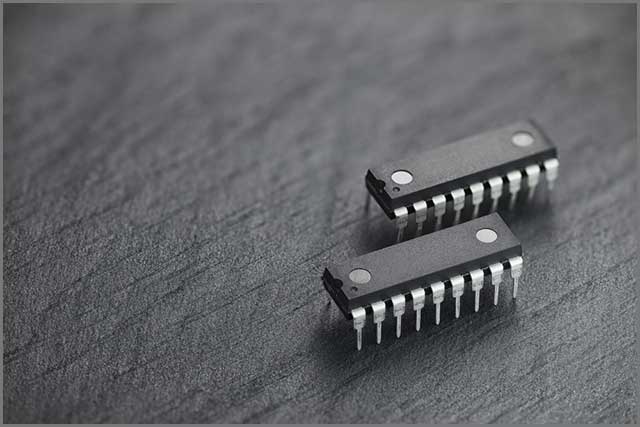 Alt – PCB packaging
3.10 Temperature
The gain and noise figure of your amplifier can change due to a rise or fall in the operating temperature. Most RF amplifiers can work from −40°C to +85°C. Some can even withstand temperatures of up to 105°C.
Temperature is also dependent on the surrounding environment.
4. What Does a Neutralizing Circuit Do in an RF Amplifier?
 Alt- Amp PCB neutralize
The Neutralization Circuit is an essential component in the RF amplifier circuit. It counteracts or neutralizes the effects of interelectrode capacitance.
The interelectrode capacitance between the base and collector plate has negative feedback. This feedback is responsible for reduced amplifier gain. You need to counter the negative feedback with positive regenerative feedback. A feedback capacitor feeds back a signal that remains in phase with the base.
Neutralization helps in correcting unwanted feedback. The feedback from the node-cathode grid present in the amplifier can be other types of feedback. Neutralizing removes all such problematic feedback.
As a result, you can use your amplifier without any issues. The performance also improves without any disturbances.
Neutralization is also essential for stability and linearity. It’s critical to a professional environment where everything needs to be perfect.
5. How to Calculate RF Signal Through Amplifier?
We need to calculate the RF signal through an amplifier for several reasons. It includes performance analysis. Here are the steps to determine the RF signal with your amp. You will need a spectrum analyzer with an inbuilt generator for the job.
Then follow the easy steps mentioned below-
Step 1
Connect your tracking generator output to the spectrum analyzer input using cables. Don’t forget to connect the adapters if your amplifier has them.
Step 2
Now activate the dedicated normalize function on your equipment. It will bring down the curve to 0dB. You currently have the perfect condition to begin your testing.
Step 3
Now hook up your amplifier between your spectrum analyzer input and generator output; it will show you the frequency response curve of your RF signal. You can even calculate the frequency range for maximum gain and the best performance.
6. How to Test an RF Amplifier?
Commercial solutions: You can directly use commercial testing solutions for your RF amplifier. They are hassle-free ways to test your microphone. The spectrum analyzer is an example of commercial RF amplifier testing solutions. You can always expect accurate results with zero chances of errors.
Using detectors:
Detectors are high to test signal powers. They are, in reality, diodes. It can transform the RF carrier to a proportional voltage. They measure the output of the RF circuit, and You will need oscilloscopes for the test. The detectors are suitable for measuring signal strength even for wireless systems.
Spectrum measurement:
You can do a test to find out the RF spectrum when switching. You don’t need to create spurious signals that disturb other receivers nearby. The tools are excellent for measuring the noise figure for various RF applications. They can do it over a wide range of frequencies.
Conclusion
We hope that the above terms and factors can provide you with guidance. Before specifying the required RF amplifier, you need to know which signal to use. Determine the frequency range and bandwidth; Do the math; Calculate gain and output power. Also, please pay attention to the packaging.
RF amplifier is a vital component. Its component converts the signal into high-resolution waves. Make sure you rely on reliable PCB brands for design. It will increase the chance of success.
You can navigate to OurPCB. Know why a good PCB design is needed. Prepare for a successful RF amplifier project.
Special Offer: Get $100 off your order!
Email [email protected] to get started!