Are you new to the induction heater circuit? Or you probably have heard of it—but you don’t know how it works?
Then, this article is for you—but we must be honest with you!
Designing and creating an induction heater circuit could be tricky, especially if you don’t have sufficient information and experience. It’s slightly different from high current PCBs.
Luckily, we’ve created this article to help you break down the subject into understandable bits and reveal the secrets behind the induction heater circuit—how to design and create one.
So, let’s get started.
Contents
- What Is an Induction Heater Circuit?
- The Working Principle of Induction Heater Circuit
- Simple Induction Heater Circuit Designs
- 1. Induction Heater Circuit Design Using the Mazzilli Driver Concept
- 2. Induction Heater Using a Center Tap Work Coil
- How to Make a DIY Induction Heater Circuit
- Step 1: Get Required Components
- Step 2: The Required Tools
- Step 3: Transistors and Cooling
- Step 4: The Capacitor Bank
- Step 5: Making the Work Coil
- Step 6: Building the Circuit
- Final Words
What Is an Induction Heater Circuit?
Electromagnetic Induction Heat
An induction heater circuit is a device used to generate heat for conductive materials—like iron—in a purely non-contact process. Plus, you can use the induction heater circuit for commercial and personal projects.
Although, it’s ideal for your DIY projects. For commercial purposes, it’s suitable for soldering, heat treating, brazing, and other heat-related processes.
One remarkable feature of the induction heater circuit is;
It generates heat inside an electronic appliance without using any external source of heat or form of contact. Thus, you can heat appliances quickly—without contamination.
Special Offer: Get $100 off your order!
Email [email protected] to get started!
The Working Principle of Induction Heater Circuit
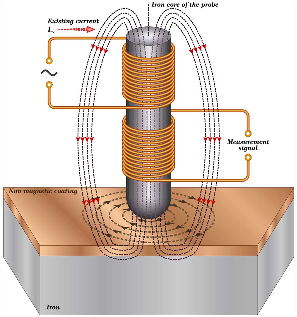
Diagram showing magnetic induction test method
For an induction heater to work, it needs a high-frequency magnetic field to heat a conductive material through an “Eddy current rapidly.”
Eddy currents are reverse currents—generated when there are rapid alternations in the magnetic field. When this magnetic field hits the conductive object, it generates electrical current flows inside the conductor called eddy currents.
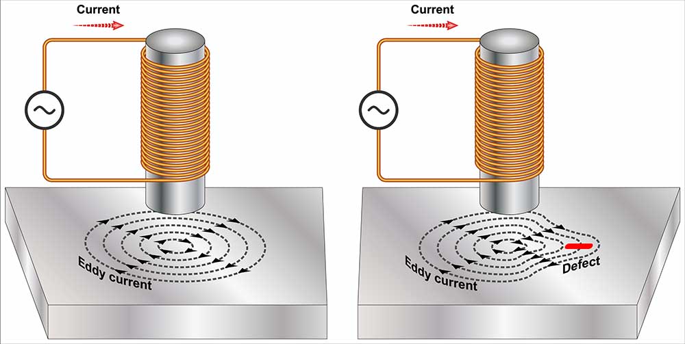
Eddy Current Testing
But that’s just the primary part. Here’s the deal!
What makes the induction heater circuit work is how inefficient it is as an electrical transformer.
How?
For an electrical transformer to generate electricity, the core must be compatible with the induced frequency. When the opposite happens, the heating rate surges.
So, if an iron-cored transformer requires a low-frequency range of around 50-100 Hz to work, the core would get hotter if you increase this frequency. Therefore, increasing the frequency to a higher level, like100kHz, would generate intense heat within the iron core.
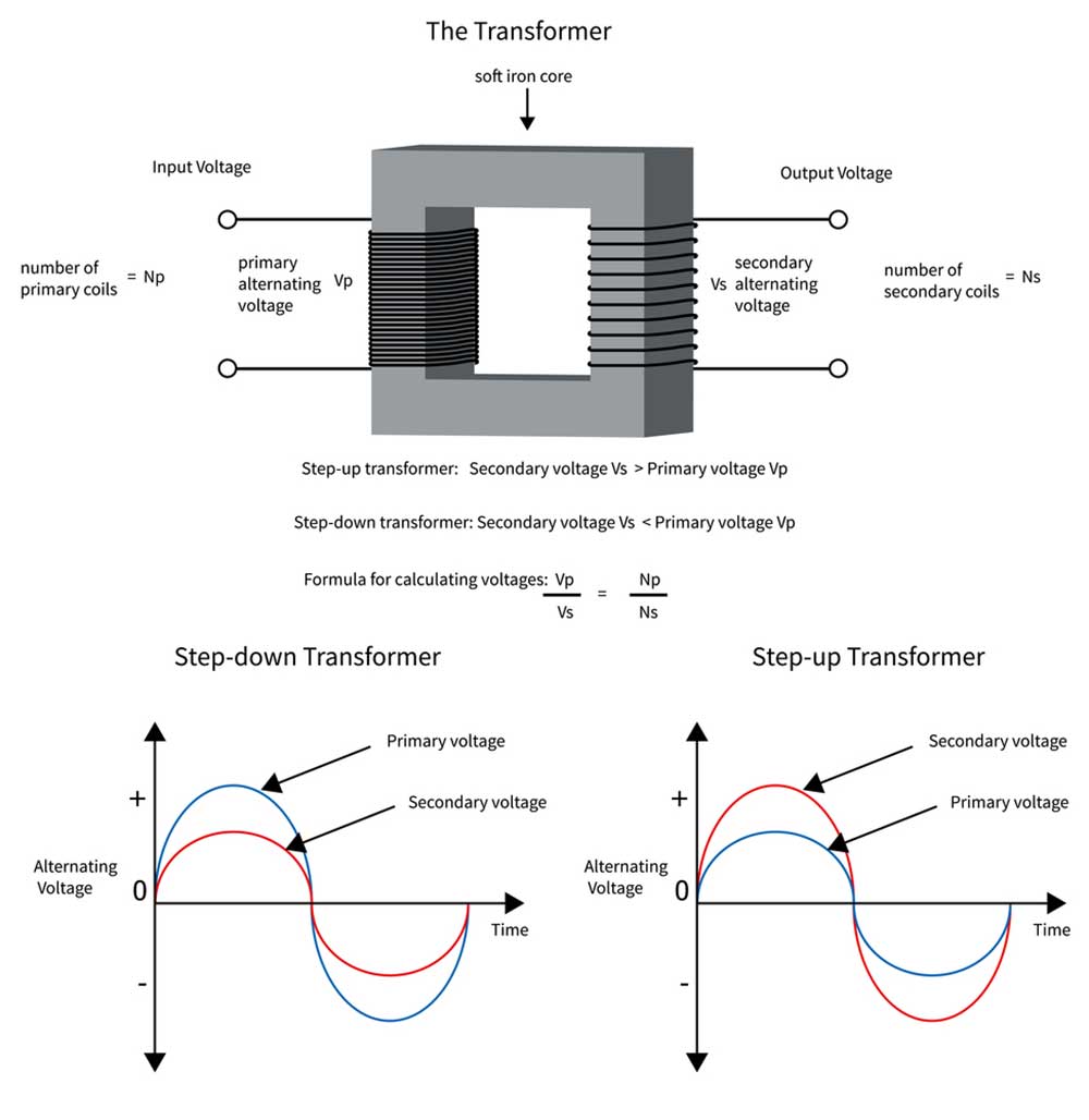
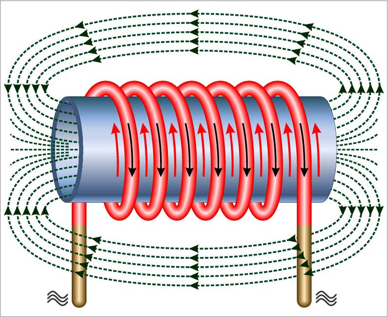
Electrical transformer changing voltage and current
The same thing applies to an induction heater circuit. When you increase the frequency, the induction coil receives heat, resulting in the iron core’s rapid heating load (cooktops or tip of a soldering machine).
Simple Induction Heater Circuit Designs
Here, we will discuss two simple induction heater designs and the materials required to create them.
1. Induction Heater Circuit Design Using the Mazzilli Driver Concept
The first design shows a very efficient ZVS induction concept from the well-known “Mazzilli driver theory.”
So, the design uses one work coil and two current limiter coils. Its configuration doesn’t need a center tap from the significant work coil. Hence, the system becomes effective and rapidly heats the load. Again, the work coil uses the full-bridge push-pull action to heat the load.
The best part is:
You can easily purchase this model at a reasonable price. For example, here’s a diagram of the circuit below:
Induction Heater Designer Mazzilli Driver Concept
Source: Wikimedia
For this design to work, it needs two high-power MOSFETs with a supply input ranging from 5v to 12v and current from 5 amps- 20 amps (depending on your selected load).
Meanwhile, the power output of this design can go as high as 1200 W—when you increase the input voltage to about 48v and current to 25 amps. At this point, the heat you would get could melt a 1 cm thick bolt in just a minute.
Finally, the dimensions of your work coil should be 30mm long and 19mm (for the inside diameter), and 22.5mm (for the outside diameter). The double current limiter coils should be 24mm long and 14mm in diameter.
2. Induction Heater Using a Center Tap Work Coil
This second design also has a ZVS concept, but it isn’t as efficient as the first one because of its need for a center tap work coil. Thus, the work coil here is a center bifurcation.
The most significant element in this design is the L1. Thus, you must construct it with very thick copper wires to retain heat during induction. Also, ensure you connect the capacitor close to the L1 terminals to maintain the specified resonant frequency (200kHz).
Here’s a diagram of what this design looks like:
Induction heater with Center Tap Work Coil
Source: Wikimedia
For your L1 (induction heater coil), you can wound 1mm copper wires in a bifilar coil or the form of two separate coils as an alternative method. Also, you can purchase the previous design online.
Here are the parts you need for this design:
- 330 ohms 1/2 watt for R1, R2
- BA159/ FR107 for D1, D2
- IRF540 for T1, T2
- 10,000uF/25V for C1
- 2uF/400V for C2
- 25 amp diodes for D3 to D6
- 7812 for IC1
- 2MM brass wound pipe with a diameter of about 30mm for tL1
- 2mH choke from a wound 2mm magnet wire on a ferrite rod for L2
- 0-15V/2 Amps for TR1
- Regulated 15V 20 amp DC for the power supply
And that’s all you need for this design.
How to Make a DIY Induction Heater Circuit
Here are the steps to build a 30 KVA Induction heater and the components needed:
Step 1: Get Required Components
To build this circuit, you will need a few components. Thankfully, you can get most of these for free by salvaging old CRT TVs or other electronic devices.
So, here’s a list of the things you need.
- Fast diodes
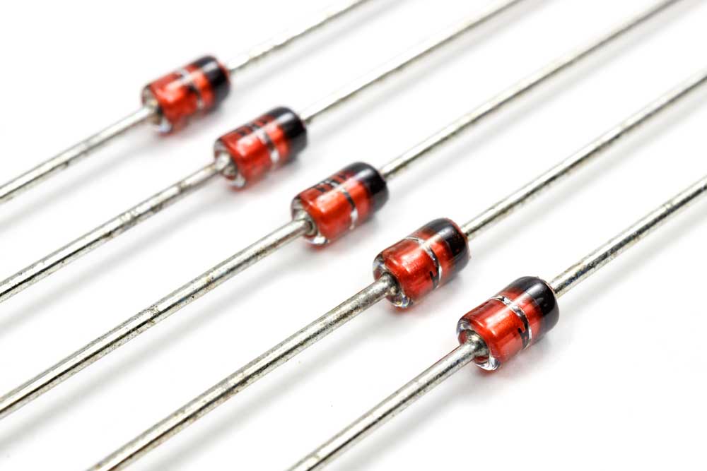
Zener Diodes
- Resistors (10k)
- Thick copper wires
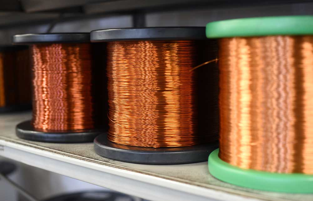
The row of copper wires
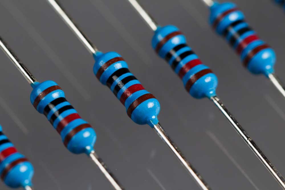
- Ohm resistors (220)
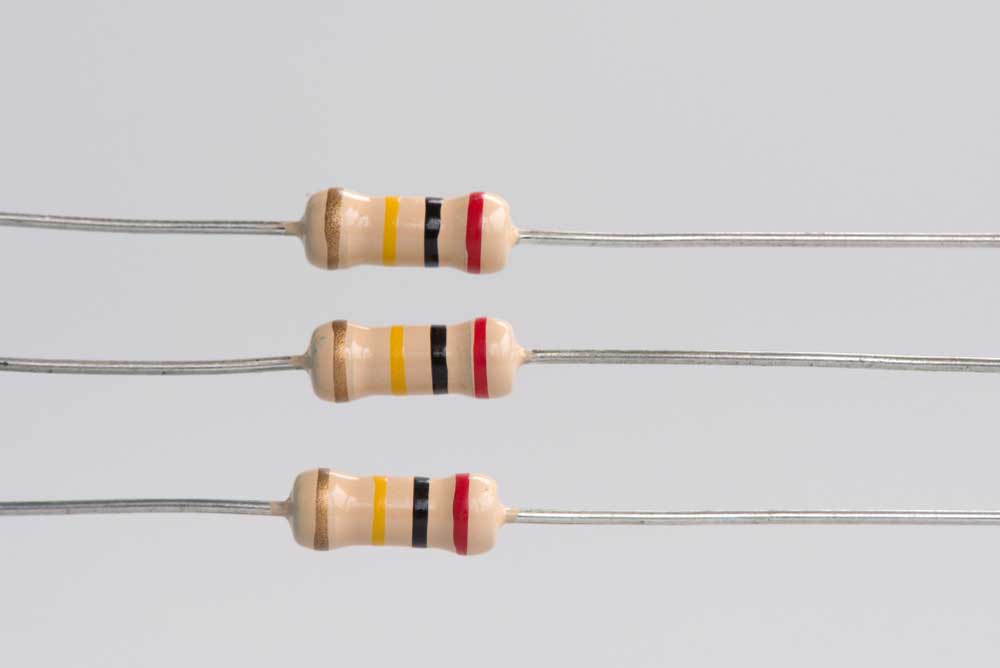
Ohms resistors ready for insertion
- IRFP260 Mosfets
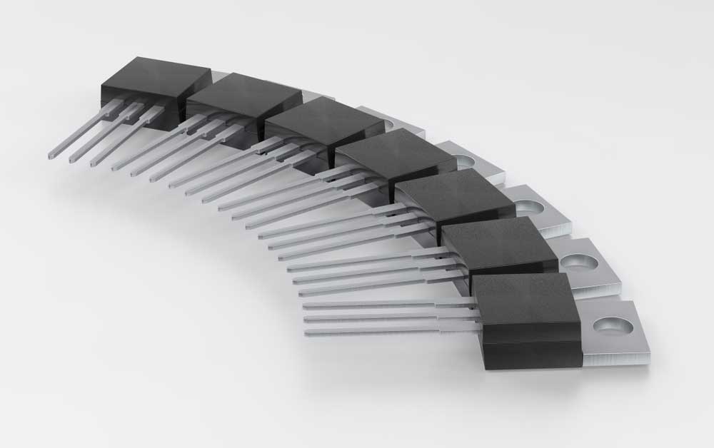
Mosfets package
- Capacitors (10x/.047uF)
- Inductors (2x50uH)
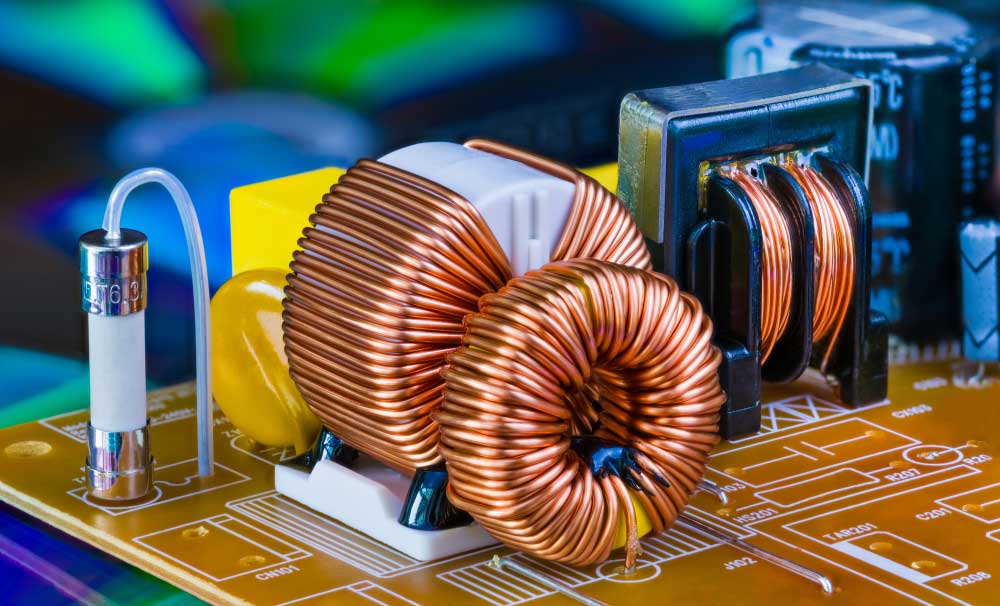
Toroidal Inductors
- Wood

- Two sealed lead batteries
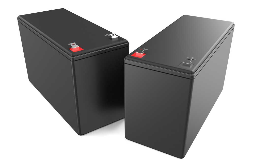
Sealed Lead batteries
Step 2: The Required Tools
Next, you need to get the tools required for this DIY project; the tools you need are:
- Wire cutters
- Multimeter
- Soldering iron
Step 3: Transistors and Cooling
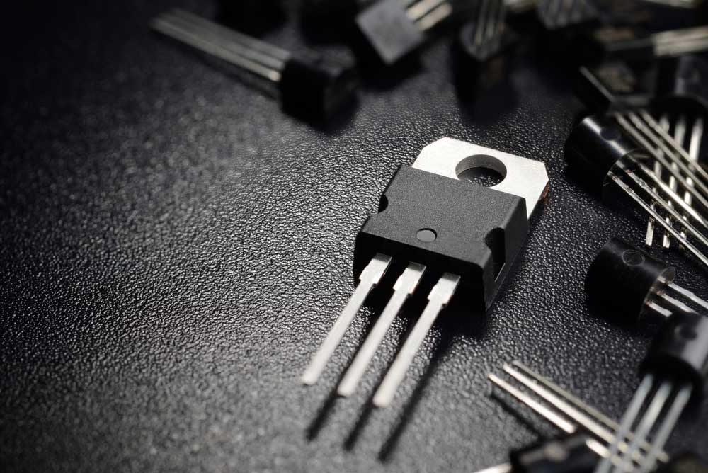
Power Transistor
Here, we’re using the ZVS concept (Zero voltage switching), so the transistors don’t have to get very hot. So, if you want to run this circuit for more than a minute, you need to mount the transistors on a single heat sink.
Ensure your FETs get the proper isolation they require—by checking them with your multi-meter. Also, make sure you isolate the metal backs of the FETs from the heat sink to avoid damages. Therefore, you’ll get continuity if they aren’t isolated.
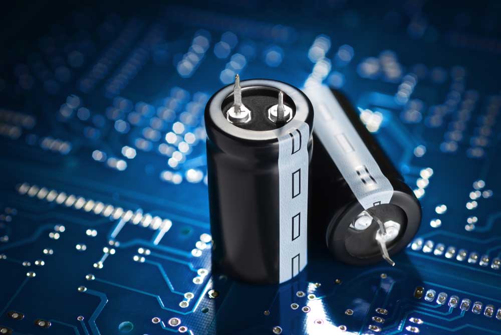
Step 4: The Capacitor Bank

Capacitors on a circuit board
Create a copper ring and add 10.047uF capacitors to increase the capabilities of your capacitor bank to .47uF and ensure to create enough space for cooling.
Why? Because the capacitor will always get extremely hot because of the constant current flowing through them. For the circuit to work correctly, the capacitors need a value of 0.47uF.
Therefore, place the capacitors parallel to the work coil.
Step 5: Making the Work Coil
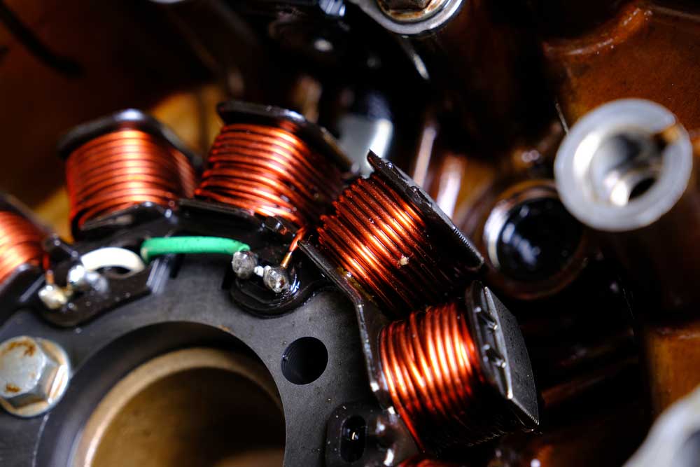
Magnet coil Unit
This step is the essential part of the circuit. So, here, the work coil generates the magnetic field for the induction heater circuit to work. Hence, you’ll need a copper wire to make this coil. To create it, wrap the copper wire around a PVC pipe nine times.
Step 6: Building the Circuit
First, twist the diodes with the 10K resistor and solder them between the gate and the base of the MOSFET. Next, solder the MOSFETS to a perf board and use the bottom to join two fast diodes amid the trench and the gates of your FET.
Afterward, attach the VCC wire of your power supply to the transistor gates through two resistors (220 ohms). Again, solder the capacitor bank and the work coil parallel to each other and join each end to a different drain.
Finally, run some power through each MOSFET drain with the inductors (2x50uH). You can also use toroidal cores with ten wire turns for your inductor. And your circuit is ready to go.
Therefore, you can use a piece of wood as a base to support all the components of your induction heater.
Final Words
There you’ve it: everything you need to know about induction heater circuits and how to create one.
We produced this article to help you understand the principles and secrets behind induction heater circuits. So, with the information delivered here, you can easily integrate it into your project.
If you require any help concerning this topic, feel free to contact us.
Special Offer: Get $100 off your order!
Email [email protected] to get started!