Contents
- What is a Frequency to Voltage Converter?
- Block Diagram of F-V Converter
- Frequency to Voltage Converter Circuits
- Frequency to Voltage Converter Circuit Based on TC9400 IC
- Frequency to Voltage Converter Using LM331
- Using the VFC32 Configuration
- Using IC LM2917
- Frequency to Voltage Converter Applications
- Summary
What is a Frequency to Voltage Converter?
As the name suggests, a frequency to voltage converter is an electronic device that converts the input frequency signal into a voltage output. The components responsible for the sinusoidal input frequency conversion include resistor-capacitor networks and operational amplifiers. Operational amplifiers do the signal processing while the capacitive network eliminates the ripple frequencies or frequency-dependent ripples.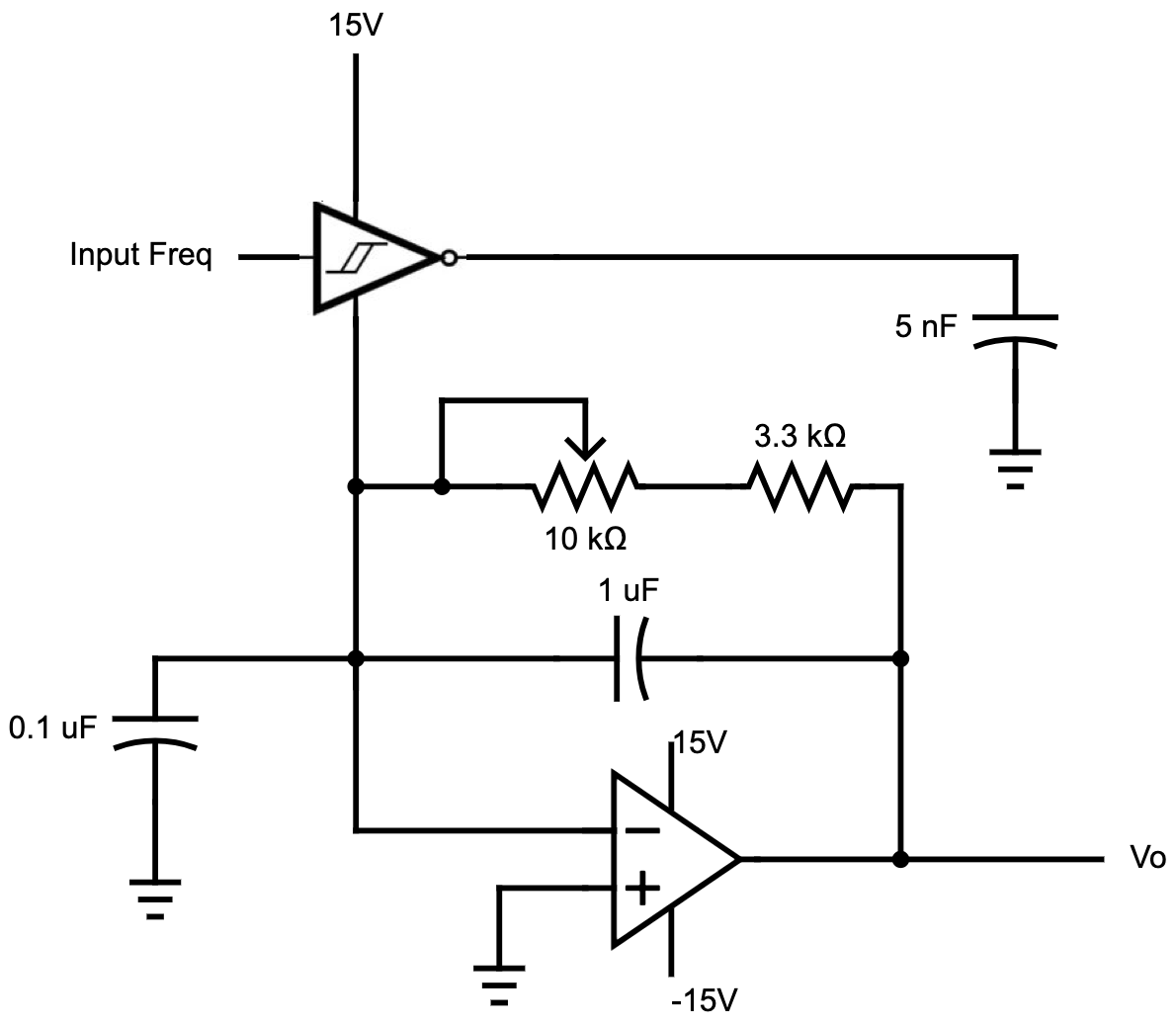
Op-Amp and RC networks circuit diagram
In most cases, the input signal frequency ranges from 0 to 10kHz, while the output is around 0 to -10V.Special Offer: Get $100 off your order!
Enjoy $100 off your order! No hidden fees and no minimum order quantity required.
Email sales@ourpcb.net to get started!
Email sales@ourpcb.net to get started!
Block Diagram of F-V Converter
The easiest way to explain the device is by using a block diagram.
A frequency to voltage converter circuit diagram
After the capacitor gets charged to a certain level, it discharges into the connected integrator or the low pass circuit. This charging-and-discharging process occurs at all the frequency cycles of the input signal. The one-shot multivibrator and the precision switch generate a frequency pulse up to a specific amplitude and period, which goes into the averaging network. After that, the output from this filter comes out as a DC voltage, making the conversion complete.Frequency to Voltage Converter Circuits
The following are the four primary frequency to voltage converter circuits.Frequency to Voltage Converter Circuit Based on TC9400 IC
You can wire the TC9400 IC in a voltage-to-frequency converter circuit or vice versa. To make the converter, you need the following components:- Nine resistors
- One trimmer potentiometer
- Two diodes
- Five capacitors
- One-shot circuit
- Charge discharge control unit
- Integrator op-amp
- 3uS delay circuit
- All the necessary drivers

A frequency to voltage circuit diagram based on the TC9400 chip
Frequency Conversion
Conversion begins at pin 11 (internal comparator's non-inverting input), where the signal input frequency flows in. The minimum frequency to trip the comparator should be +/-200mV. Any sine wave frequency below this value will not work. Once the frequency wave goes into the negative, the internal comparator switches to low. When low, the 3uS delay circuit activates the C4 charge/discharge circuit, connecting it to the reference voltage. Meanwhile, the integrating capacitor C5 also charges to a specific voltage amount. The potential difference between pin two and seven forms the reference voltage as this supply voltage operation occurs. On the other hand, when the frequency signal wave crosses to the positive side, the internal comparator's output goes high. This high output disables the C4 charge/discharge network, leading to a short circuit on the C4 leads. However, the voltage across C5 gets retained because the only available discharge path (R10) has a very high resistance (1M). Therefore, the voltage stored at C5 becomes the output voltage, while R9 sets the bias current in the chip. The divider network consists of R6 and R7, and it is responsible for ensuring the input signal's threshold tracks the supply voltage at all times. Diode D2 is the main component in the clamp circuit, and it prevents the input frequency signal from going too far in the negative to switch on the comparator. Thus, it acts as a level shifter. You can calibrate the circuit by adjusting the potentiometer R3 to get an output of 0V when there is no input signal.Frequency to Voltage Converter Using LM331
The LM331 is a high precision frequency to voltage converter that can also function as a voltage to frequency converter. It provides excellent linearity and a wide dynamic range, ideal features for several applications. The circuit is quite simple as you only need the following components:- Six resistors
- One trimmer potentiometer
- Three capacitors

A frequency to voltage converter based on the LM331 IC
Conversion begins by differentiating the input frequency using C3 and R7, then feeds the pulse into the chip via pin 6. In the negative cycle of the frequency sine wave, the built-in comparator activates the timer circuit (R1 and C1). At any time, the current flowing out of the IC is always proportional to the input signal and the timing circuit value. Similarly, the output voltage will be proportional to the frequency signal at R4 (load resistor).Using the VFC32 Configuration
When using the VFC32 configuration, the 500pF capacitor and the 12K & 2.2K resistors form the capacitive network of the input signal. These components make the comparator's input compatible with the 5V logic triggers. The comparator then switches to the associated single-shot stage at each falling edge of the input frequency wave.
A frequency to voltage converter based on the VFC32 IC
In this circuit, the reference threshold input set for the comparator is around -0.7V. Therefore, if the input signal is lower than 5V, you can adjust the divider network accordingly. Capacitor C2 is responsible for smoothing and filtering the output voltage waveform. Larger C2 values lead to better control over the voltage ripples in the output, although the response might be slow to the varying input frequency signals. On the other hand, low C2 values lead to poor ripple filtration, but the response is quick to the fast-changing frequencies. The system operates using the charge-and-balance theory using the output ramp to trigger the one-shot stage before changing direction.Using IC LM2917
The LM2907 and LM2917 are similar in many ways, and their electrical specifications include the following:- Can double low ripple frequencies.
- Tachometer input built-in hysteresis.
- The tachometer pin referenced to the ground can be directly compatible with all magnetic pick-ups with varying reluctance.
- The ground reference tachometer is safe from input signal frequency variations exceeding the supply voltage of the chip or -ve potential below zero.
- The output pin linked to the internal common collector transistor can sink up to 50mA. As such, it can operate solenoids directly, integrate with the output, or act as CMOS inputs.

The LM2917 chip pinout diagram
The maximum ratings for the chip are:- 28V supply voltage
- 25mA supply current
- 28V internal transistor collector voltage
- 28V differential tachometer input voltage
- +/-28V input voltage range
- 1200-1500mW power dissipation

A typical LM2917 frequency to voltage converter circuit diagram
Frequency to Voltage Converter Applications
The frequency to voltage converter circuit applications include the following:- Frequency to voltage converter in tachometers (digital tachometers)
- Frequency difference measurement
- Vibration-based touch switch sensors
- Vehicle engine measurement instruments
- Speed controllers and governors
- Car door lock control
- Horn, clutch, and cruise control
Summary
As you can see, a frequency to voltage converter is a critical device, especially in the automotive industry for speed measurement. However, there are different ways to build the circuit to suit various applications. If things get a little bit confusing, contact us for more information about the best IC and circuit for your project. We will also assemble the circuitry in a PCB at a reasonable price so that you can get your project running in no time.Special Offer: Get $100 off your order!
Enjoy $100 off your order! No hidden fees and no minimum order quantity required.
Email sales@ourpcb.net to get started!
Email sales@ourpcb.net to get started!