Top 10 Classic Car Wiring Harness Manufacturers | Full Guide
Finding the right wiring harness manufacturer for your vintage ride can be a real headache. Those beautiful old machines need special wiring that looks period-correct

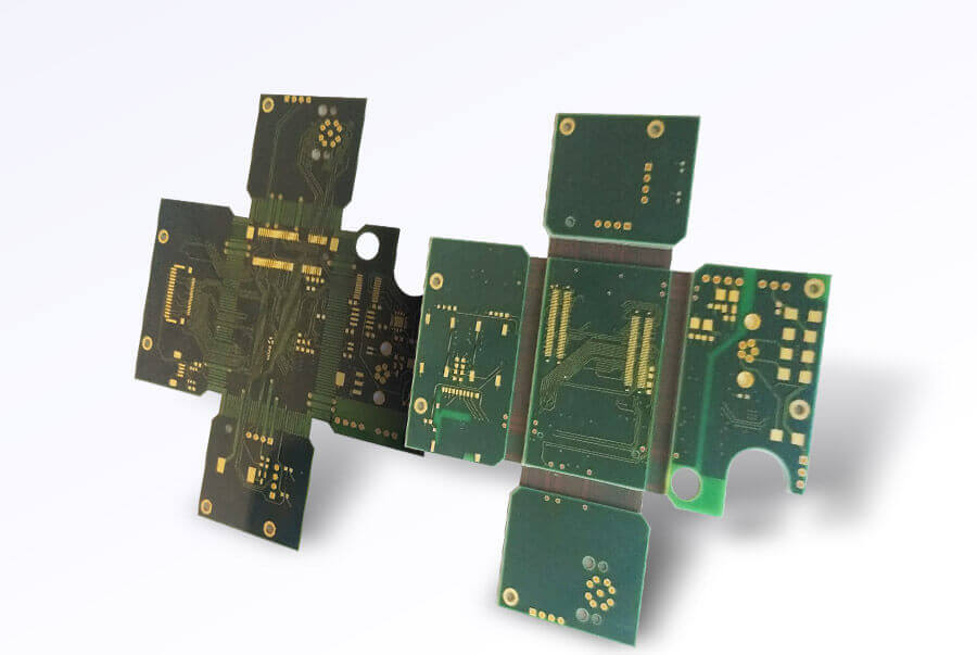
OurPCB provides high-quality rigid-flex PCB manufacturing and assembly services. Rigid-flex PCBs combine flexible and rigid layers, offering durability and space efficiency for complex electronic designs. We ensure precision engineering, strict quality control, and fast turnaround times to meet your requirements.


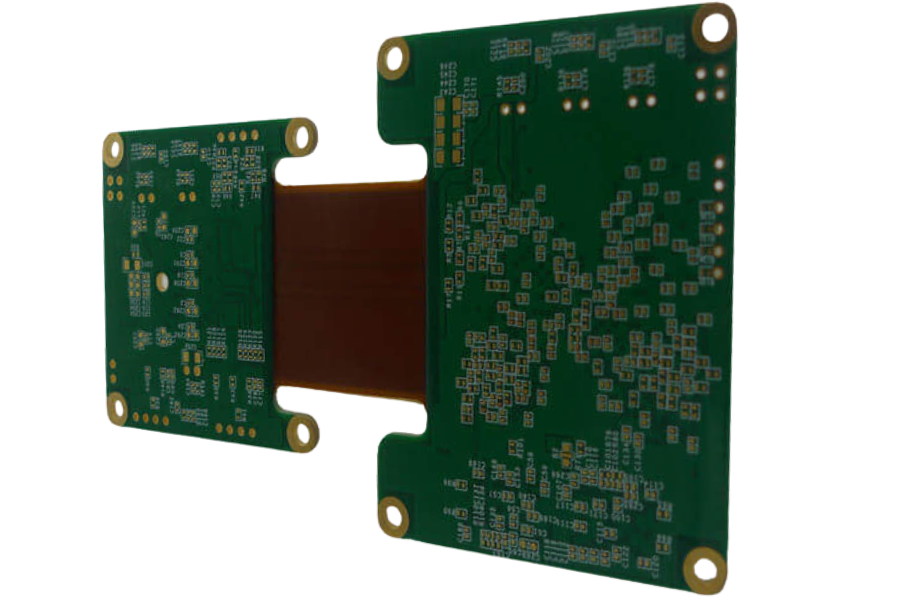

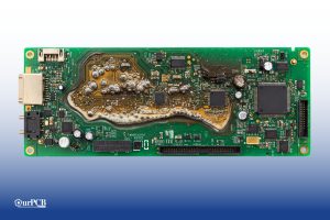
Rigid-flex PCBs are a hybrid circuit board combining components of rigid and flexible PCBs, and are used to connect electronic components in a variety of both consumer and non-consumer devices. This board type can be folded or flexed continuously on the flexible section, which usually joins two rigid parts.
| Project Item | Normal Capability |
|---|---|
| FPC Base Material (Adhesive) | ShengyiSF302:PI=0.5 mil,1 mil,2 mil;Cu=0.5 oz,1 oz ShengyiSF305:PI=0.5 mil,1 mil,2 mil;Cu=0.33 oz,0.5 oz,1 oz |
| FPC Base Material (Adhesiveless) | SongxiaRF-775/777:PI=1 mil,2 mil,3 mil;Cu=0.5 oz, 1 oz (Ultimate:PI=1 mil,2 mil,3 mil;Cu=2 oz) Xinyang:PI=1 mil, 2 mil;Cu=0.33 oz, 0.5 oz, 1 oz Taihong PI=1 mil, 2 mil;Cu=0.33 oz, 0.5 oz, 1 oz Dubang AP:PI=1 mil, 2 mil, 3 mil, 4 mil;Cu=0.5 oz, 1 oz (Ultimate:PI=1 mil,2 mil,3 mil,4 mil;Cu=2 oz) |
| Layer | 1-6 Layers (Ultimate:7-10 Layers) |
| Thickness of Finished Product (Flex part,no stiffener) | 0.05-0.5 mm (Ultimate: 0.5- 0.8 mm) |
| Size of Finished Products(Min) | 5 mm*10 mm (Bridgeless);10 mm*10 mm (Bridge) Ultimate:4 mm*8 mm (Bridgeless);8 mm*8 mm (Bridge) |
| Size of Finished Products (Max) | 9 inch*14 inch Ultimate:9 inch*23 inch (PI≥1 mil) |
| Impedance Tolerance | Single-Ended:±5Ω(≤50Ω),±10%(>50Ω) Ultimate:Single-Ended:±3Ω(≤50Ω),±8%(>50Ω) |
| Impedance Tolerance | Differencial:±5Ω(≤50Ω),±10%(>50Ω) Ultimate:Differencial:±4Ω(≤50Ω),±8%(>50Ω) |
| Tolerance of Finger Width | ±0.1 mm (Ultimate:±0.05 mm) |
| Min Distance to the Edge of Finger | 8 mil (Ultimate:6 mil) |
| Min Distance between Pads | 4 mil (Ultimate:3 mil) |
| Minimum Laser Hole | 0.1mm |
| Minimum PTH | 0.3mm |
| Min NPTH Tolerance | ±2 mil (Ultimate +0,-2 mil or +2 mil,-0) |
| Solder Bridge Min Width(bottom copper<2OZ) | 4 mil(Green),8 mil |
| Solder Bridge Min Width(bottom copper 2-4OZ) | 6 mil,8 mil |
| Overlay Colour | White、Yellow (printed character:White) |
| Type of Surface Treatment | OSP HASL, Lead free HASL, Immersion gold, Hard gold, Immersion silver, OSP |
| Selective Surface Treatment | ENIG+OSP,ENIG+G/F |
| Project Item | Normal Capability |
|---|---|
| FPC Base Material (Adhesive) | Shengyi SF302, Shengyi SF305 |
| FPC Base Material(Adhesiveless) | Songxia RF-775/777, Xinyang, Dubang AP |
| Low flow prepreg | Taiguang EM-37B; Ventec: VT-47N |
| Common rigid board material | Refer to standard rigid board materials |
| Special rigid board material | Arlon: 85N; Rogers: RO4000 series; Nelco: N4000-13 series; Ventec: VT-901 |
| Layer | 2-30 Layers; review required: ≥20 layers |
| Thickness of Finished Product | 0.3-4.0mm; review required: >3.0 mm |
| Size of Finished Products(Min) | 10mm*15mm (no internal positioning designs, panel size <50mm*50mm) |
| Size of Finished Products (Max) | 18inch*22inch; Ultimate:18inch*29inch |


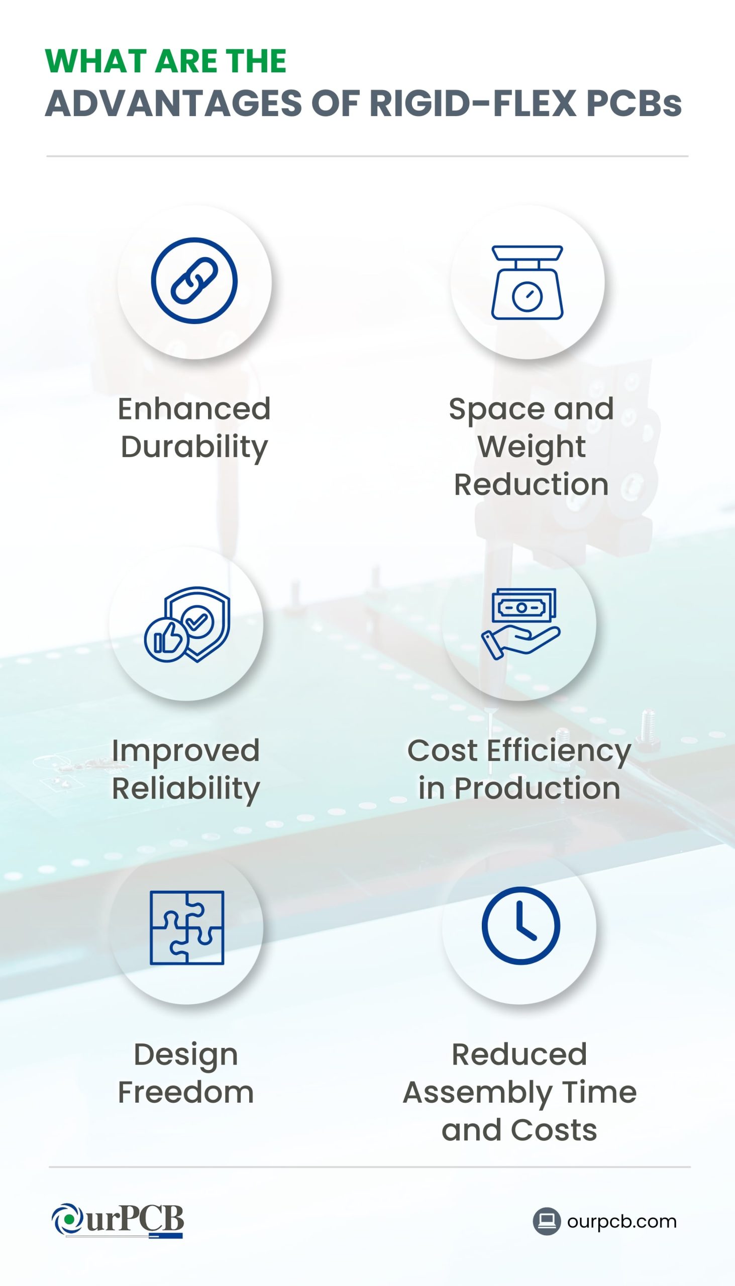

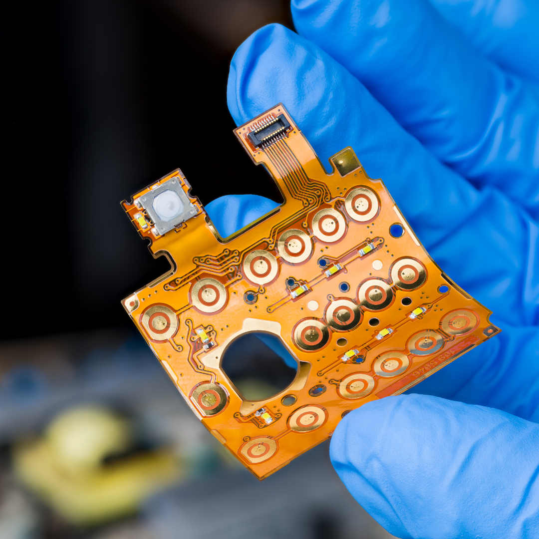
The flexible part of the circuit is vibration-and shock-resistant, meaning it can hold heavier components without cracking. These boards are also more resistant to high temperatures, radiation, and other harsh environments, making them suitable for rugged applications.
Rigid-flex PCB designs are more challenging to create because you have to use a 3D development space to have better spatial efficiency. But the result is a lightweight and space-optimized design that fits in compact electronics like wearables.
Compared to regular PCBs, the rigid-flex type has fewer connectors and interfacing materials. Interconnections are potential sources of failure, so this design makes the PCBs more reliable.
Manufacturing rigid-flex PCBs is more expensive than building their rigid counterparts, but the cost savings come during PCB assembly. Since they replace wired interconnects (harnesses and connectors) with conductive copper layers inside the board, the assembly costs and error risks are lower.
The ability of rigid-flex circuits to adopt complex shapes and compact sizes gives you the freedom to experiment with different device designs because the PCB will fit inside more easily.
With fewer interconnections and parts, assembling rigid-flex PCBs takes less time, minimizes wiring errors, and reduces costs because you won’t need manual labor to insert the connector wiring joints.
The cost of rigid-flex PCBs varies widely depending on the order quantity, complexity and number of layers. Here is a detailed cost comparison for low volume orders based on complexity and layers:
| Rigid-Flex PCB | Medium Complexity | High Complexity |
|---|---|---|
| 4-Layer | $50 – $200 | $200 – $1,000+ |
| 8-Layer | $100 – $500 | $500 – $2,000+ |
These prices are influenced by factors such as the order quantity, the number of layers, the complexity of the design, the materials used, and the specific manufacturing processes required. For example, military and aerospace applications often use more advanced materials and designs, which can increase costs significantly.
Rigid-flex PCBs are generally more expensive than standard rigid or flexible PCBs due to their complex manufacturing process, which involves combining rigid and flexible materials to create a single integrated board. This integration helps in reducing the overall size and weight of the device while improving reliability and performance in demanding environments.
For precise pricing tailored to your specific project requirements, please request a free quote by filling out our form.
We manufacture 2 to 30-layer rigid-flex PCBs with a 2-week lead time. Solder mask, silkscreen, and surface finishes match rigid PCBs, customized to your requirements.
We use polyimide, Rogers, and FR4. FR4 suits rigid boards, polyimide is for flexible circuits, and Rogers is ideal for high-frequency applications.
We ensure tight tolerances and controlled impedances using advanced equipment. Our expertise guarantees precise circuit wiring for all rigid-flex PCB applications.
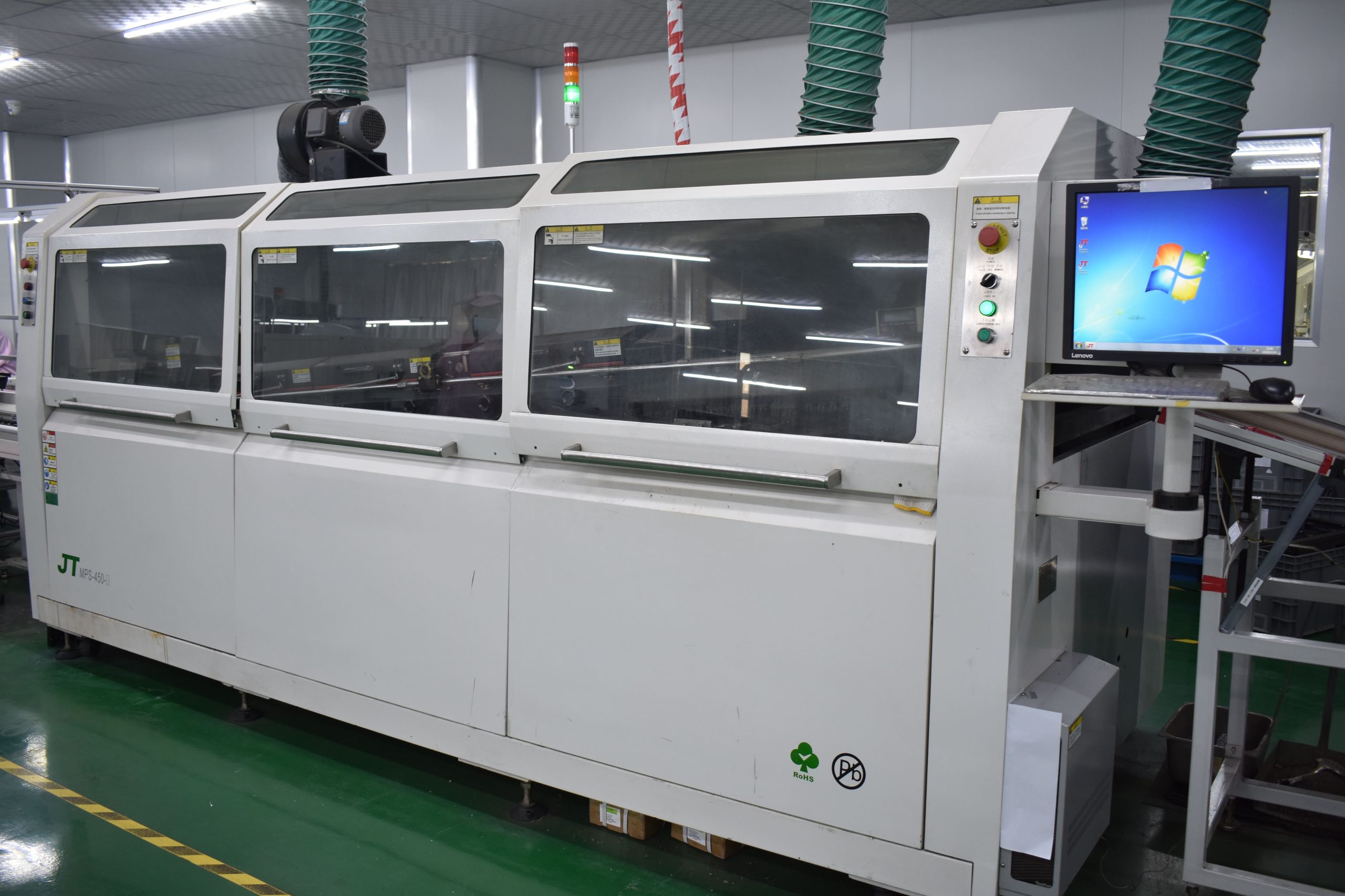
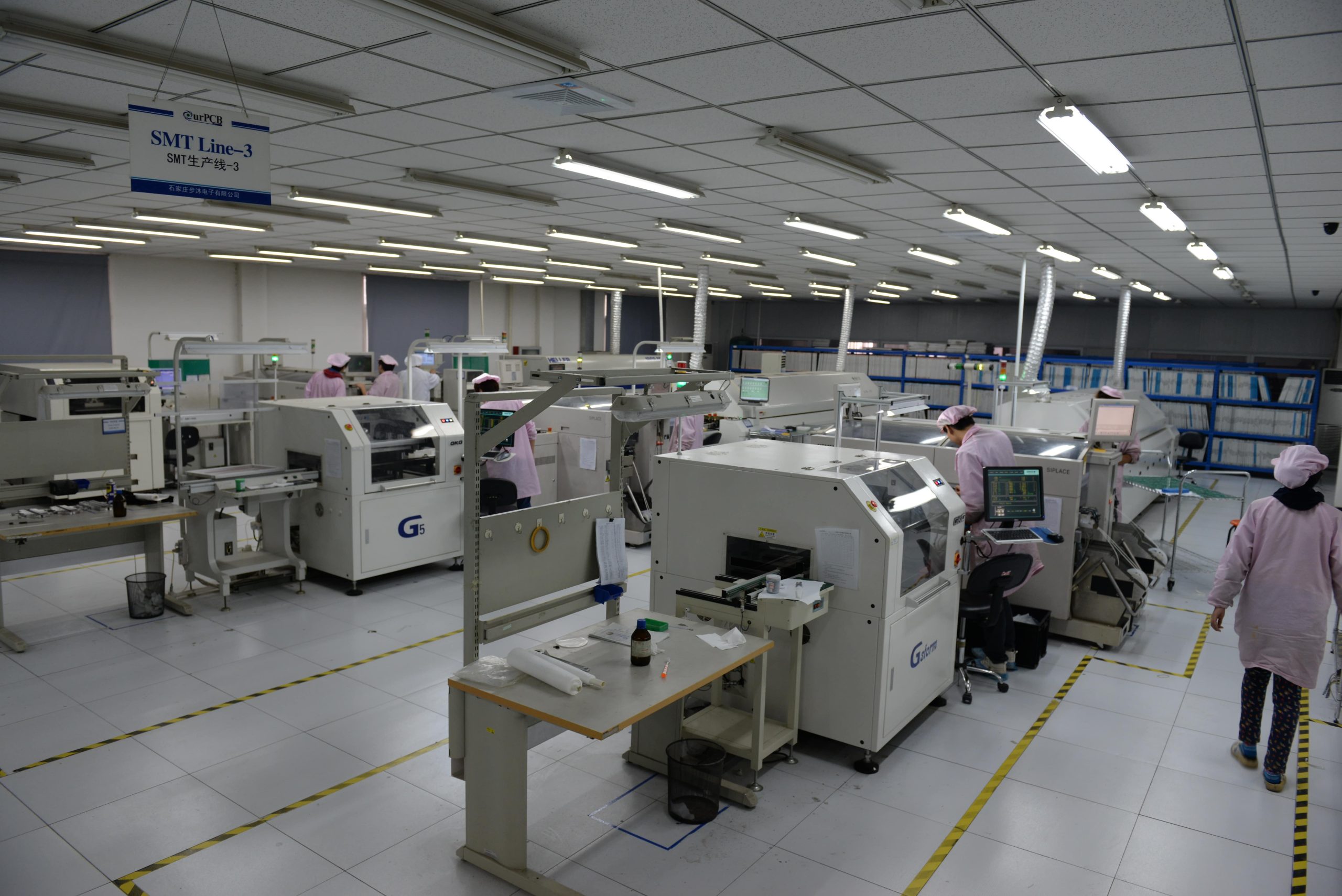
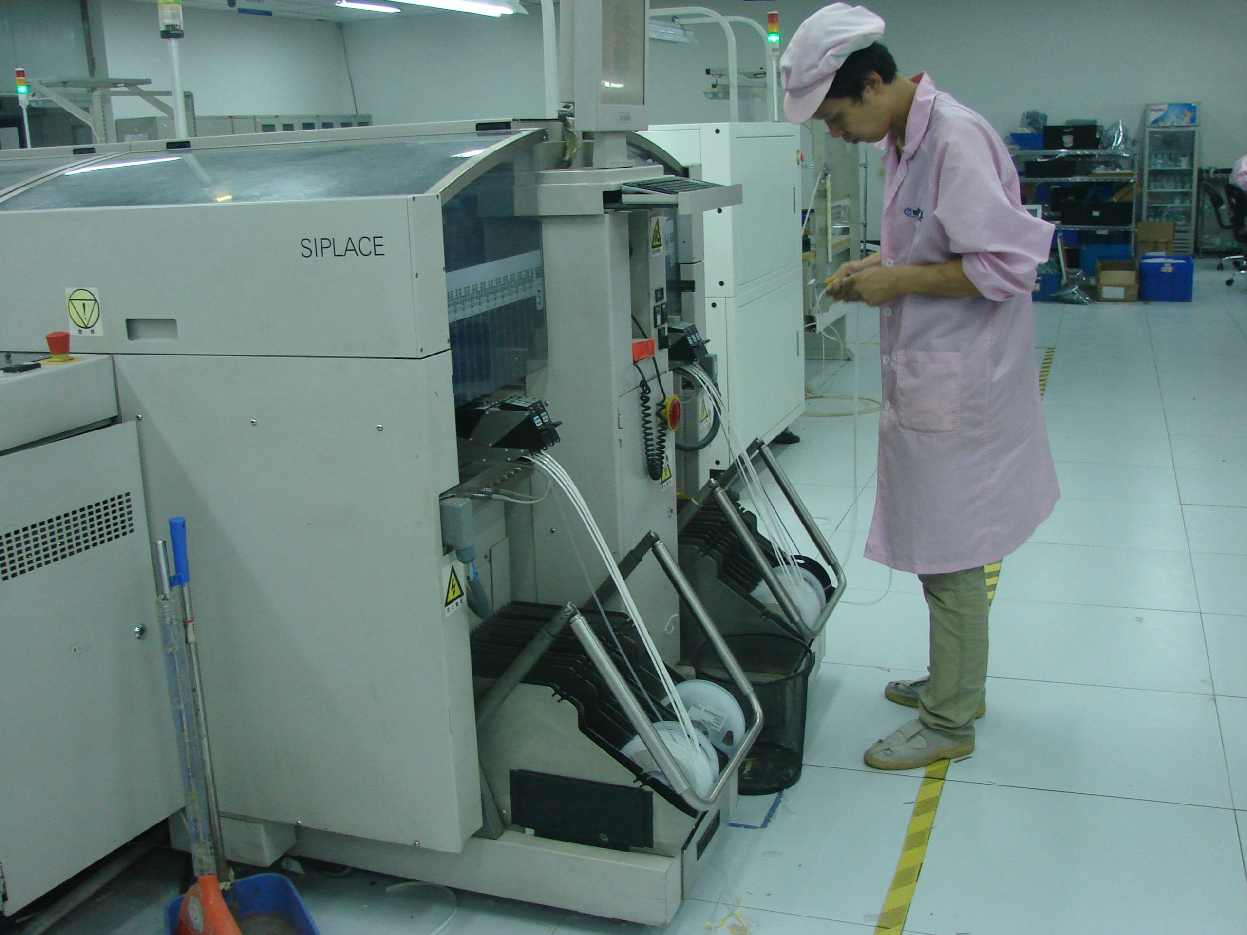
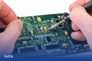
Our Shijiazhuang & Shenzhen factories assemble SMT and THT components, including BGA, QFN, SOP, leaded, and leadless carriers, even in mixed assemblies.
We manufacture buried vias, microvias, and high-density components. Our Shijiazhuang factory meets IPC 6012 Class 3/A standards for military, medical, and aerospace applications.
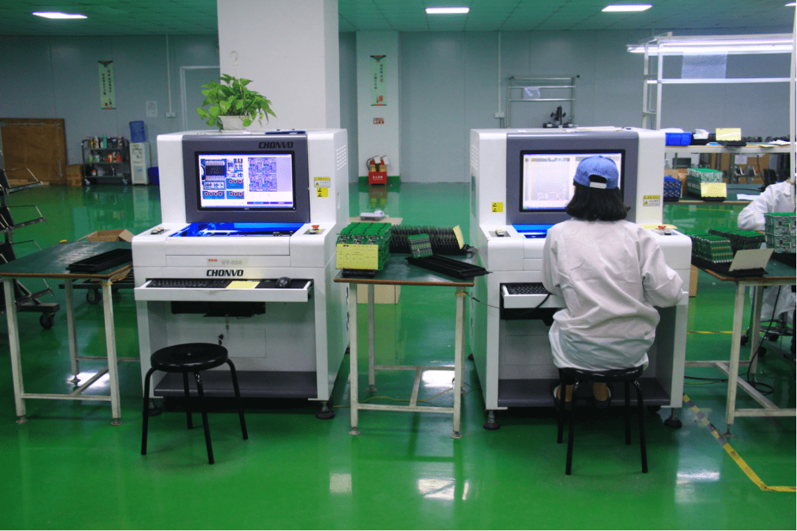
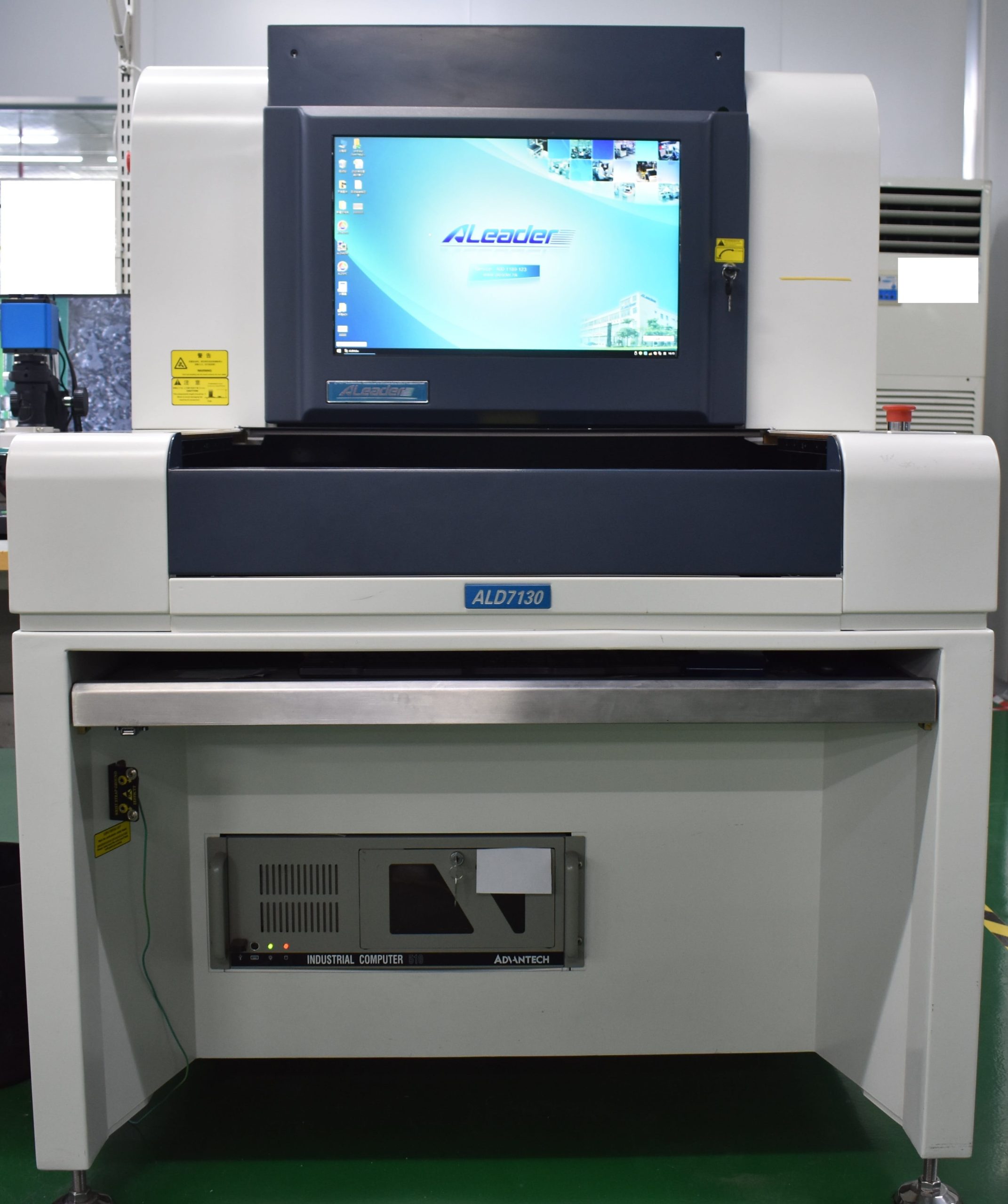
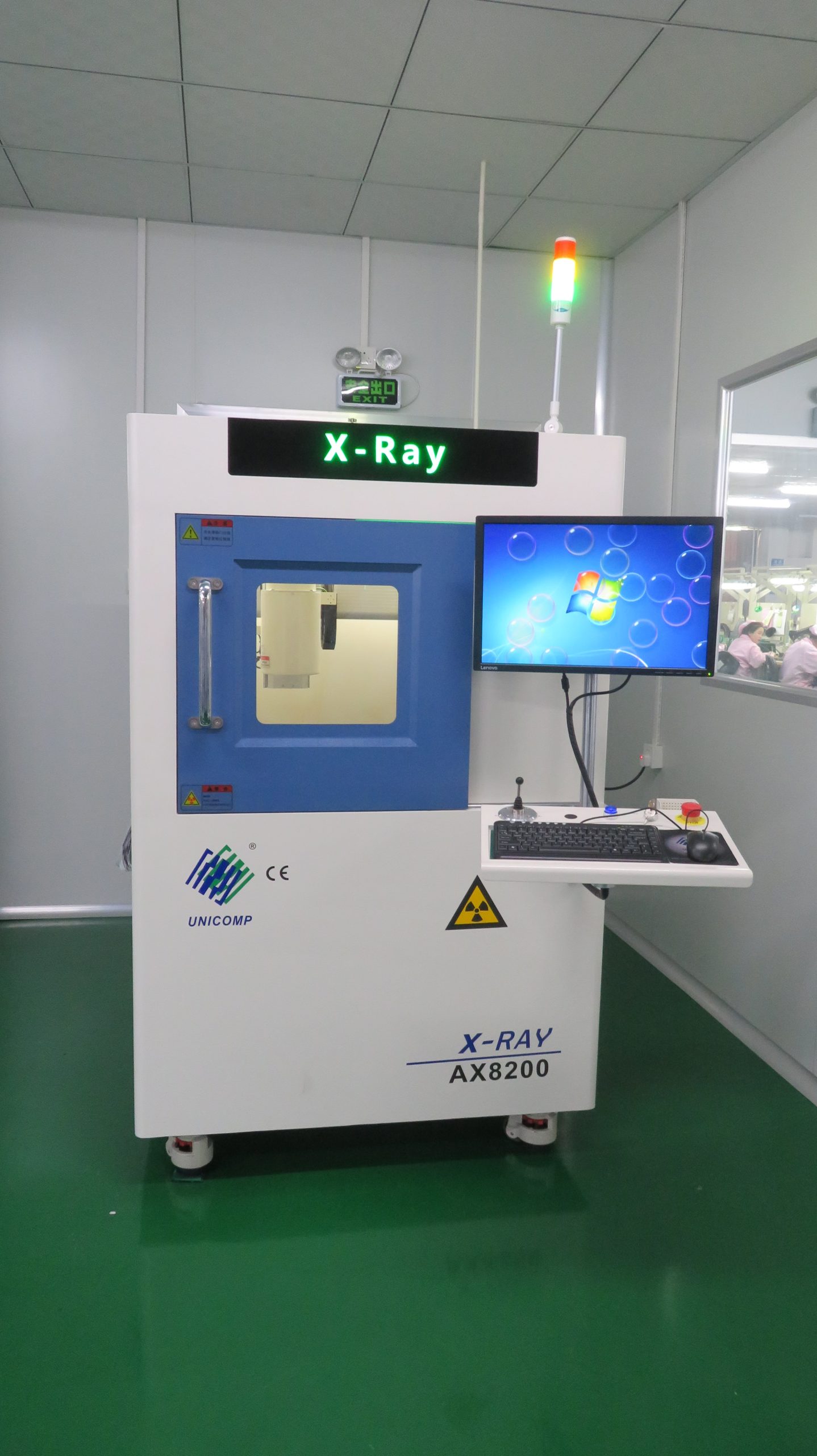
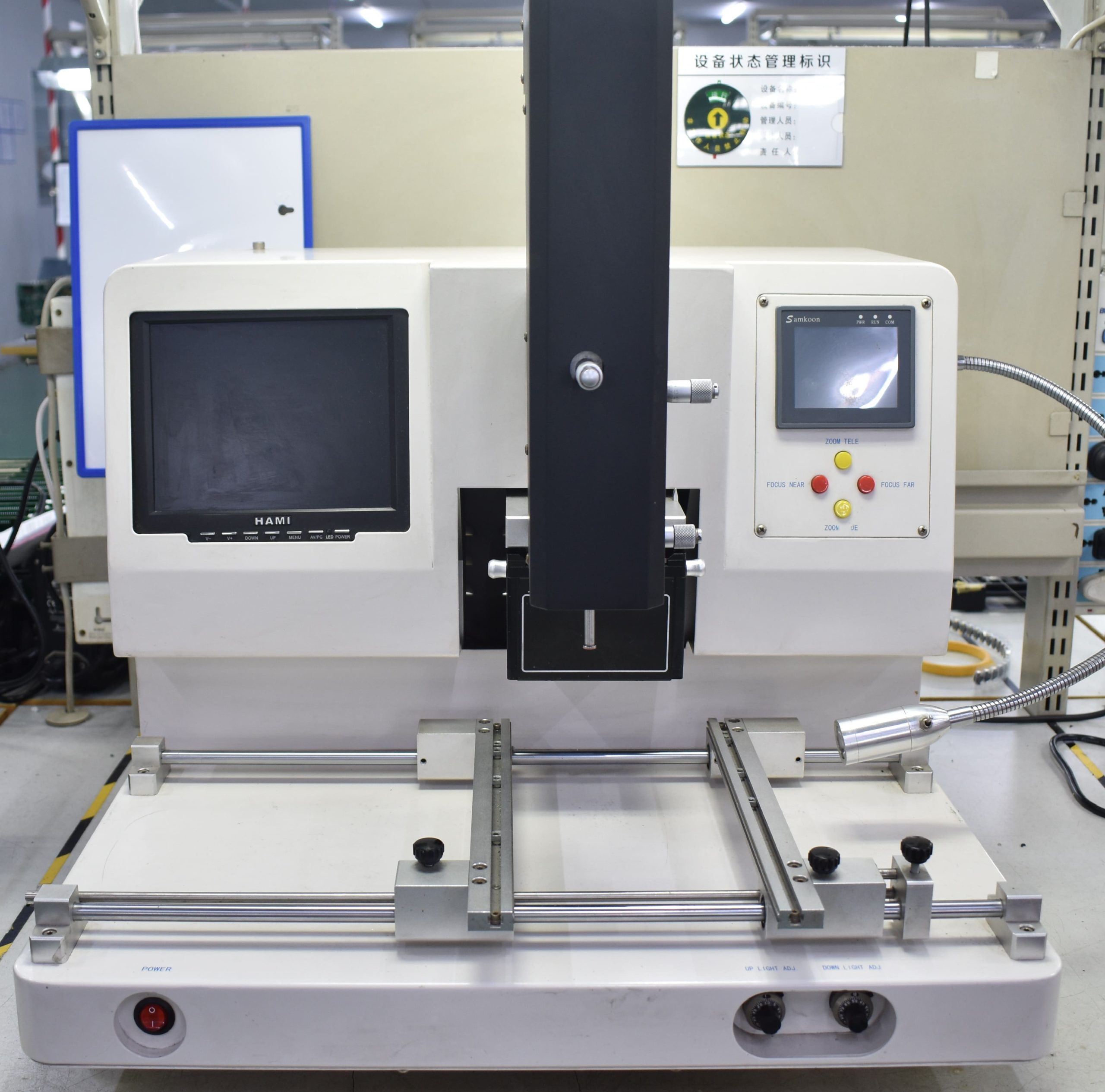
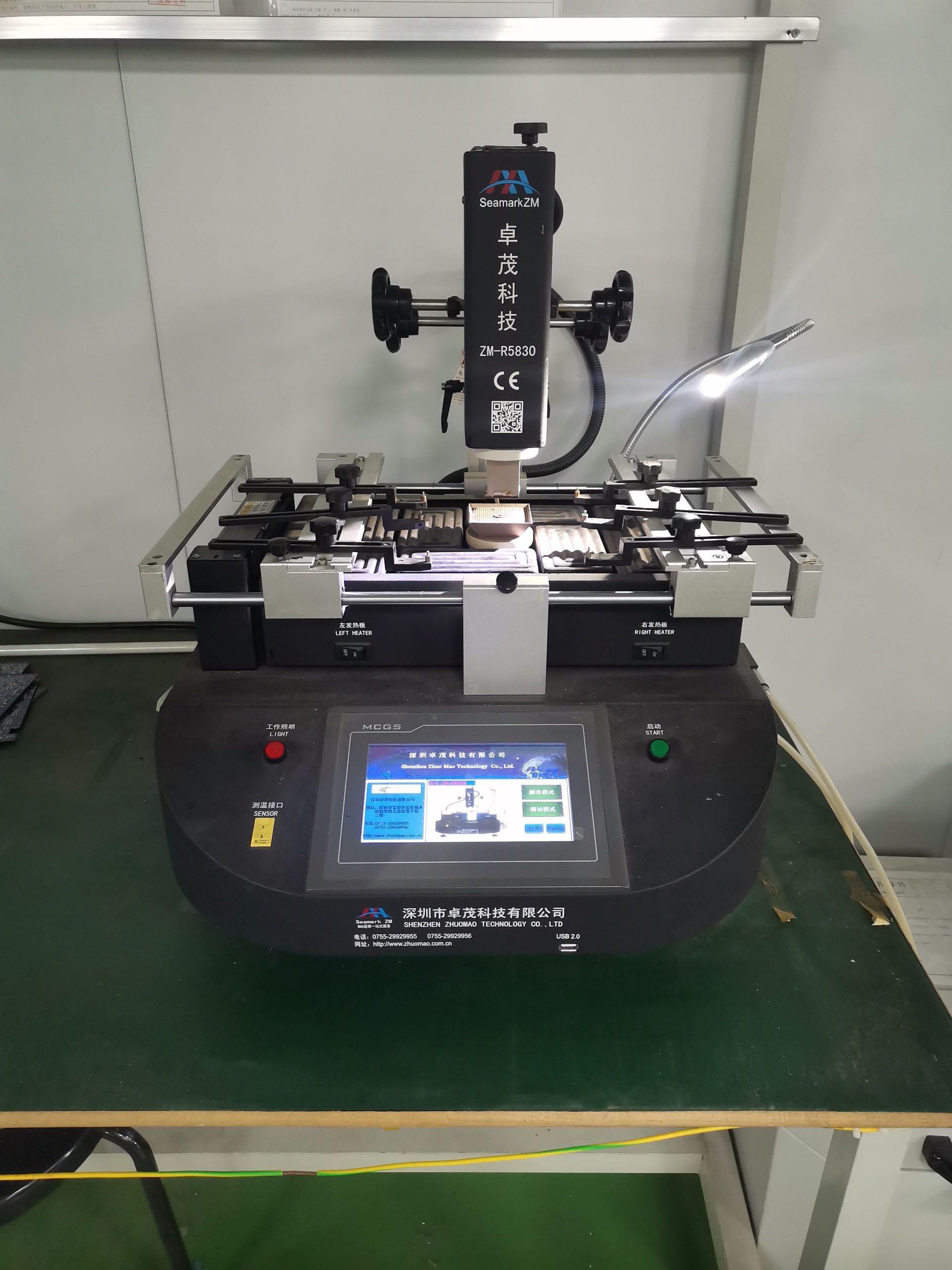
Quality control is a significant aspect of the rigid-flex PCB production process. It includes methods like ICT, FPT, AOI, automated X-ray, solderability, and burn-in testing.
Customize layers (2-30), materials (FR4, Polyimide, Rogers, Aluminum), dimensions, thickness, and finishes. Choose laminated or unlaminated designs.
Additionally, for any electronic device that requires additional protection or specific design needs, molding solutions such as custom injection molding services can help shape and house your rigid-flex PCBs to ensure they are durable and secure in their environment.
We handle everything from parts sourcing to final assembly, providing a hassle-free experience that ensures top-quality boards every time.
Whether you need a few prototypes or large-volume batches, our flexible assembly services adapt to your project’s scope and timeline.
Stay environmentally responsible with our compliant assembly processes, offering RoHS and lead-free options for safe, reliable builds.
No matter the complexity, we can assemble boards of all configurations—single-layer, multi-layer, or a mix—to match your exact specifications.
From one-off prototypes to bulk orders, we accommodate projects of all sizes without compromising on quality or turnaround time.
Join our growing community of satisfied clients who rely on our dependable assembly expertise and dedicated customer support.
Mon-Fri: 24 hours,
Sat: 9am-6pm, GMT+8
Reach us at
[email protected]
24 hours online
+86-199-30589219
Mon-Fri: 24 hours,
Sat: 9am-6pm, GMT+8
Standard PCBs are rigid, but rigid-flex PCBs combine rigid and flexible PCB properties into a single, lightweight, space-saving structure. The flexible board is also less susceptible to mechanical stress because it can absorb vibrations.
Yes. However, making these vias requires a different set of design rules because of the materials used and the manufacturing process.
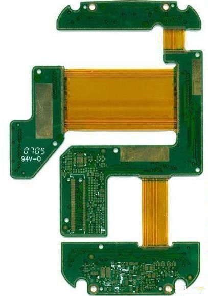
The flexible component of the Rigid-Flex PCBs can be bent, shaped, wrapped, or folded into any 2D or 3D shape. These features make Rigid-Flex PCBs perfect for use in medical and surgical equipment, consumer electronics, automotive and space applications, and smart wearable devices, that needs both properties of durable rigid boards and the flexibility of flexible circuit boards.
Yes, at OurPCB, you can conveniently order small quantities for rigid-flex PCB prototype development. We understand the unique needs of businesses, especially during product testing and validation phases, and that’s why we have no minimum order quantity (MOQ) requirement. This flexibility helps you manage costs effectively and accelerate your development process without unnecessary inventory or overhead.
Rigid-flex PCBs are essential in industries requiring durability, space efficiency, and reliability:
The main difference lies in their structure and applications:
Finding the right wiring harness manufacturer for your vintage ride can be a real headache. Those beautiful old machines need special wiring that looks period-correct
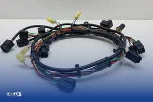
Would your car be able to run without wire harnesses? Not a chance. Wire harnesses connect all the electrical parts together. No harness means no
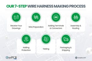
Making wire harnesses isn’t complicated. At OurPCB, we create custom wire harnesses for an expansive range of industries every day. While it’s a complicated process,

Prototype cable assemblies are the very important place in between PCB design ideas and interconnects. OurPCB brings prototype assemblies with PCB solutions to your tables.
PCB thermal management prevents component overheating through strategic heat transfer techniques. Without proper thermal control, electronics are at risk of electronic failures through weakened solder
ContentsKey TakeawaysWhat is a Multilayer-Printed Circuit Board?How do Multilayer PCB Boards Work?Multilayer PCB ApplicationsMultilayer PCB Manufacturing Process: StepsMultilayer PCB Manufacturing MachinesBenefits of Multilayer Circuit BoardsWhat
We use cookies to improve your browsing experience, which may include personal information. By clicking "Agree," you accept our Privacy Policy and cookie use. You can change your cookie settings in your browser anytime.
Agree
 Chat With Us
 Free Quote