Contents
What is Pulse Width Modulation (PWM)?
Pulse Width Modulation (PWM) is a digital signal often used in applications with sophisticated control circuitry. Other uses include measurement, conversion, power control, and communication.What is PWM output?
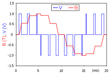
Example of PWM in an inductor
Source; Wikipedia PWM uses its digital output to drive analog devices (an analog input signal). In other words, you can operate an analog device using a modulating output signal from a digital device. Analog circuit devices include actuators, dimmable lights, speakers, and variable-speed AC motors.Duty Cycle
A duty cycle describes the amount of on-time or how high a signal is and measures in percentage. It also determines the output voltage level. The duty cycle percentage gives the time percentage whereby a digital signal is on over some time (complete cycle).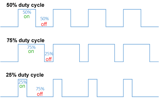
Illustration of the duty cycle
Source; Wikipedia Therefore, you’ll use the points below to interpret a duty cycle.- A 50% duty cycle shows that the digital output signal is more in the low state than a high state. The opposite is vital for a duty cycle of more than 50%.
- However, the signals spending half of the time off and the other half on results in a 50% duty cycle. It also becomes identical to an ideal square pulse wave.
- Finally, a 0% duty cycle describes a grounding/off signal, whereas a 100% duty cycle describes the signal's full scale.
Special Offer: Get $100 off your order!
Enjoy $100 off your order! No hidden fees and no minimum order quantity required.
Email [email protected] to get started!
Email [email protected] to get started!
Frequency of PWM Signal
A time period is proportional to when the digital signal completes one off-and-on cycle. Conversely, the frequency is the inverse of the period. It refers to the number of times the signal can complete a periodic change per unit. It determines the speed of signal switching between low and high states. Hence, continuously turning on and off the digital signal at high frequencies makes the output act like analog signals.PWM Application
Some of the PWM arrays of applications comprise the following;- Generating an audio signal,
- Adjusting the brightness of light emitted from a light source,
- Heating elements,
- Switching devices,
- Suitable inefficient voltage regulators,
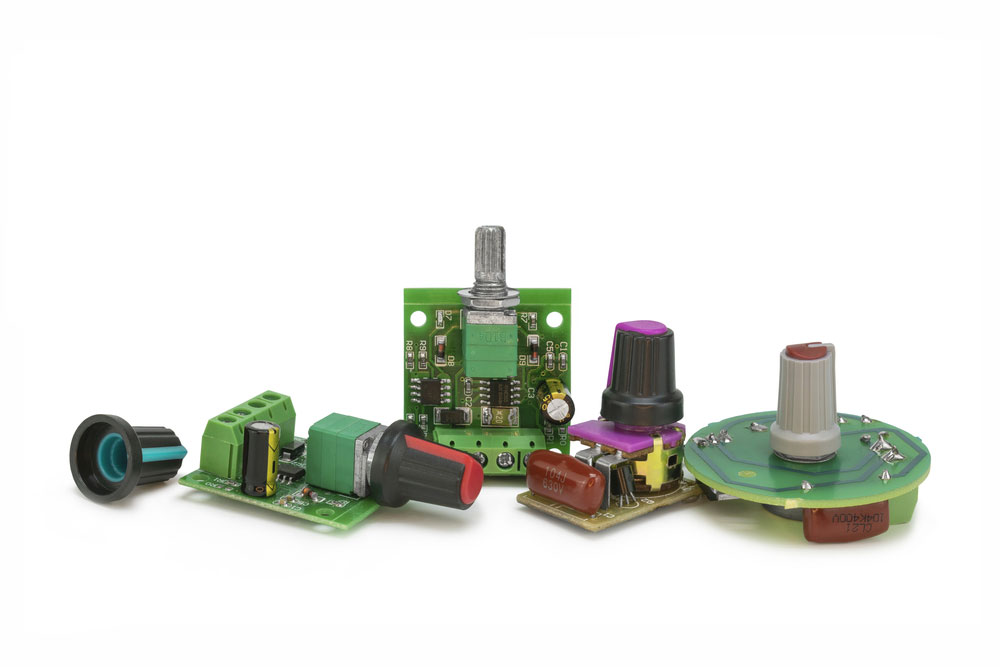
(adjustable voltage regulator and PWM speed controller)
- Communication systems by encoding messages,
- Servo motor control (inertial loads),
- Electric stove,
- Driving a buzzer with different loudness, and
- Providing an analog output.
Pulse Width Modulation Techniques
As we already know, modulation means regulating a system or device. Thus, you're bound to find the PWM process in most applications of the electronics field. PWM has a highly adaptive nature. Therefore, it is used extensively by engineers. The PWM technique lessens the power delivered to a particular electrical signal. The digital control method often works by chopping the signal into separate parts. Then, a PWM achieves its control operation by regulating the average power voltage and electric current a load receives. The method works out by repeatedly turning the switch between the source and cargo on and off. During the off- and on-periods, an increase in off-time versus on-time decreases the total load power supply and vice versa. In terms of application, you can, for example, pair a maximum power point tracking (MPPT) with a PWM. The pairing up reduces the output in a solar panel, therefore easing its battery use.PWM Function
PWM encodes a signal’s amplitude into the duration or pulse width of a different signal (carrier signal) before transmission. It’s no surprise that factories are equipping mainstream motherboards with 4-or-6 pin PWM headers since the PWM system is resourceful.How to use PWM Technology?
PWM transistor
Our first project involves using transistors to build a PWM motor controller.Materials needed
- 22k resistors,
- 10k pot,
- BC338 and BC557 transistor,
- 220ohm resistor,
- 47ohm resistor, and
- 100 uf capacitor 60V.
Circuit diagram
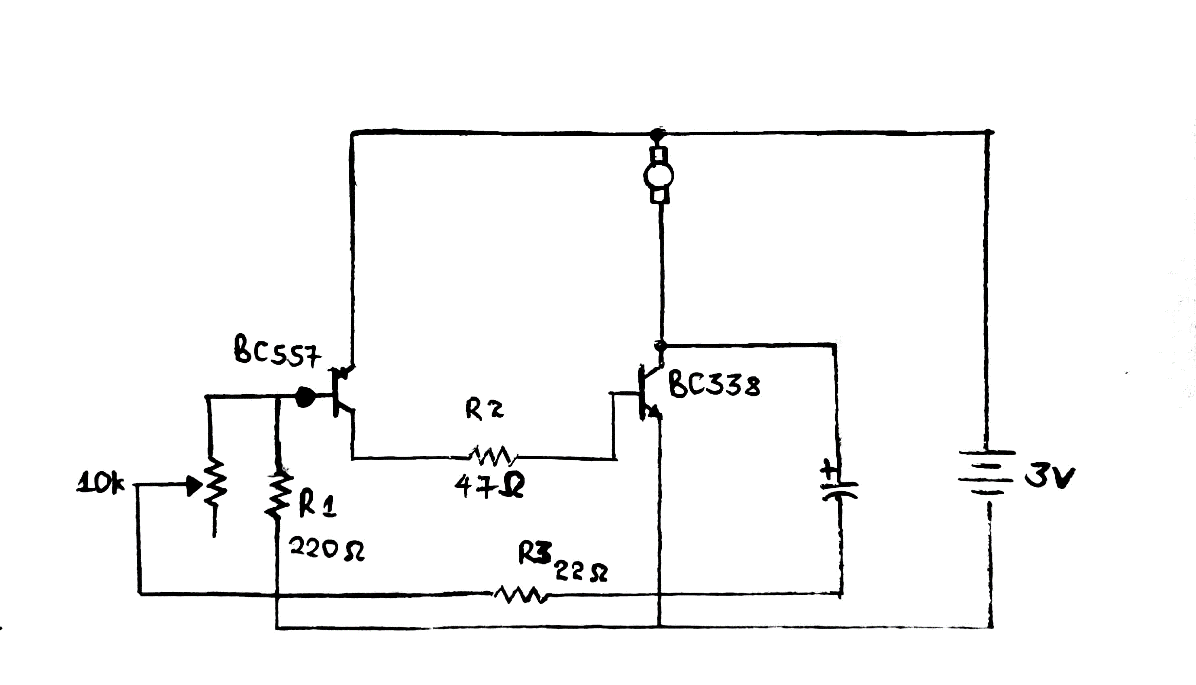
A PWM transistor circuit diagram
Designing the circuit diagram of the speed motor controller is simple and often done on a breadboard. Our digital circuit here is suitable for three motors. In addition, it gives the motor controller a series of pulses whereby the width regulates the motor running speed.Speed control
You’ll need to vary the 10k variable resistor to control the motor’s speed for the last bit. The variation also affects the pulse width sizes. Therefore, the results will be a motor speed decrease or increase depending on the direction you’ve turned the resistor.Note;
At this point, you can further implement your circuit into a breadboard, then add components or sensors for future projects.i2c PWM driver board
An i2c-controlled PWM driver board helps by increasing the number of PWM outputs you control. For example, you can have a two-pin i2c driver controlling up to 16 free-running PWM outputs.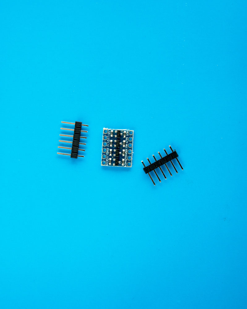
(four communication channel i2c logic level chip)
Some of its features include the following.- It has an inbuilt clock signal meaning it’s free-running and won’t need a continuous signal input via a microcontroller.
- Secondly, it has a configurable open-drain or push-pull output.
- Then, you can adjust the frequency PWN up to around 1.6KHz in an i2c.
- Also, it is 5V compliant. In other words, you can use a 3.3V microcontroller to regulate it while carefully driving up to 6V outputs.
- Fifthly, its output ensures the pin deactivates all outputs.
- Additionally, it’s RoHS compliant.
- It has six address pins. As such, you can wire approximately 62 breakouts on one i2c bus.
- Lastly, each power output has a 12-bit resolution. For instance, when using servos, it’ll mean an update rate of 4us resolution at 60Hz.
- LED light output power(green),
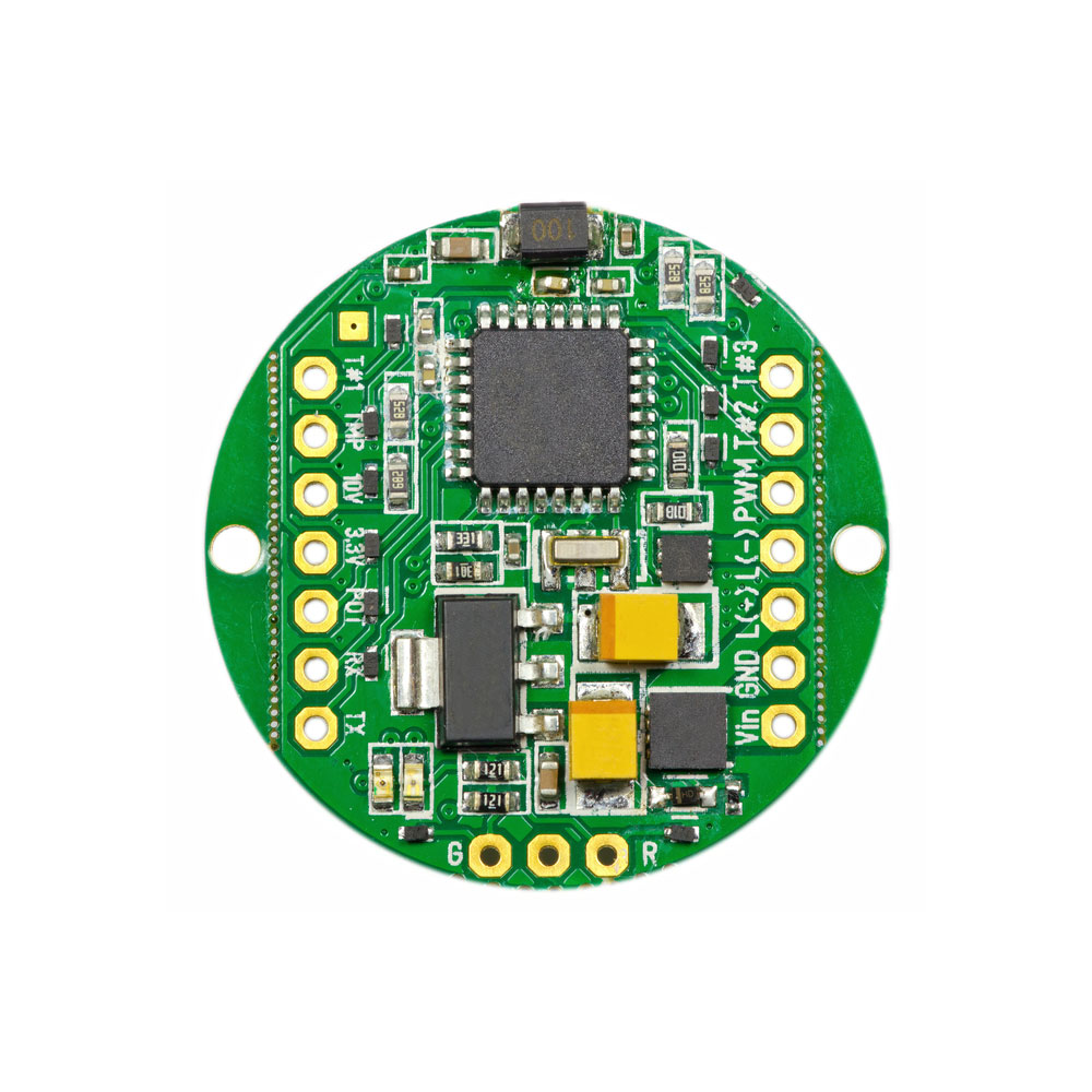
(green LED PWM PCB)
- A chainable design,
- Terminal block for power input,
- Solder jumpers for the address pins,
- In case needed, there’s a place for a big capacitor situated at the V+ line,
- 220ohm series resistors on all output lines,
- The terminal block input has reverse polarity protection,
- 3-pin connectors in groups of 4 to help plugin sixteen servos at a go.
Arduino PWM charge controller
The last project is a PWM solar charge controller. A charge controller performs current and voltage regulation from solar panels. Any rise from the solar panel’s input voltage causes the controller to regulate battery charges hence avoiding overcharges.Components required
- MOSFETs like IRF540,
- 10, 4,7k, 1k, and 330ohm resistors,
- 100uF, 35V capacitor,
- Transistors – 2N3904 or an equivalent NPN transistor,
- Breadboard,
- 16×2-character LCD,
- Red and green LEDs,
- Zener Diode 11v – 1N4741A,
- Diode – IN4007,
- Arduino UNO,
- Pin screw terminal,
- Jumper wires,
- Perforated board,
- 5A Fuses and fuse holder,
- Project box,
- Scotch mounting squares.
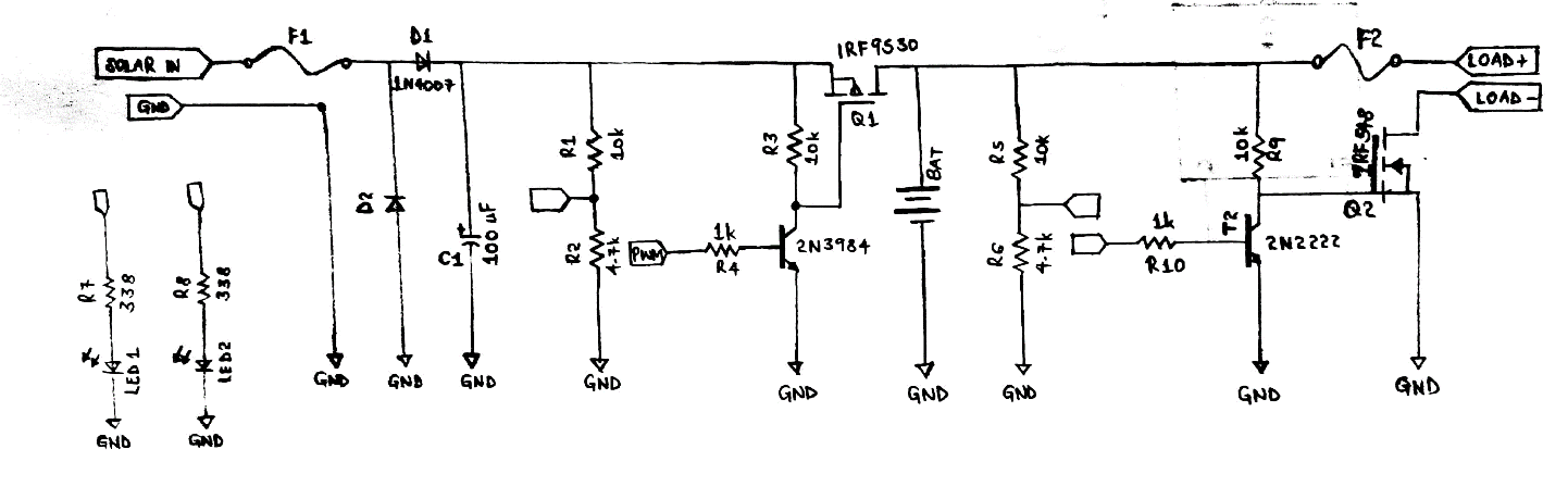
Circuit diagram of an Arduino PWM charge controller
How the electronic circuit works- Power enters the circuit through D1 from a solar panel.
- Then, the D2 Zener diode is at the input terminal to limit any overvoltages.
- C1 capacitor eliminates unwanted spikes or noise while R2 and R1 voltage dividers sense the voltage in solar panels.
- Next, Arduino analog pin AO (output pin) receives the output from the voltage dividers.
- Arduino Pin-6 then releases a PWM signal that switches on the MOSFET (Q1). Then, resistance R4 and T1 transistor drive the turned on MOSFET Q1.
- R3 functions as the pull-up resistor of the circuit gate.
- Now that the MOSFET is on, the charging process begins since power proceeds to the battery.
- R5 and R6 in the second voltage divider circuit sense the battery voltage. Later, Arduino analog pin A1 receives the voltage divider output.
- T2 transistor Q2 MOSFET, while Q2 drives the load. You can also use a relay in place of the Q2.
- F2 and F1 fuses have an overcurrent protection mechanism.
- LED 2 (green) and red LED 1 act as indicators, and you'll attach them to Arduino’s pin8 and pin7.
Conclusion
Briefly, PWM controls the amplitude of digital signals, thereby helping in regulating applications and electronic devices requiring electricity or power. It does so by quickly cycling the off-and-on phases of digital signals while having minimal power loss. For more information, don’t hesitate to contact us.Special Offer: Get $100 off your order!
Enjoy $100 off your order! No hidden fees and no minimum order quantity required.
Email [email protected] to get started!
Email [email protected] to get started!