Are you seeking the best option to differentiate and amplify two input signals in an integrated circuit?
If your answer is yes, then you need a BJT differential amplifier.
No doubt, other devices—like an Op-Amp, can work.
But this particular amplifier stands out.
It uses identical transistors, supply rails, and a collector resistor. Why?
So, we’ll compare both differential amplifiers later in the article.
So, in this article, we shall discuss the BJT differential amplifier, also known as the Bipolar junction transistor.
Interestingly, you’ll see its definition, the working process of the BJT differential transistor, its differential input signal, and many more.
So, hang in there!
Contents
What Is a Differential Amplifier?
This device is an electronic amplifier called an op-amp subtractor or difference amplifier.
It works by cutting off any voltage that two input terminals have in common.
Then, it boosts the difference between the two input voltages.
The analog circuits usually have one output Vout and two (Vin+ and Vin-) input modes.
Interestingly, both are inverting and non-inverting inputs, respectively.
Also, the output is proportional to the difference between the two input offset voltages.
So, regardless of the signal input voltage, you can represent it like this: Vout = A(Vin+ - Vin-)
Where:
A – differential amplifier gain
So, the equation above means that if both inputs have different single input values, the output voltage increases or amplifies.
But when both voltages have the same value, the output will be zero—causing a suppression.
Special Offer: Get $100 off your order!
Email [email protected] to get started!
Working Off a Differential Amplifier
If you drive the diff amplifier stage at one of the inputs, the output appears at the two collector outputs.
Also, if the input signal applies to the transistor, the circuit will have an increased voltage drop across the collector resistance.
Hence, the value will be less favorable at the transistor (T1) collector.
But if T1 goes off, the I/P1 will be negative.
And there will be a decrease in the base voltage drop across RCL1.
So, T1’s collector will have a more positive value.
On that note, we can say that applying the signal at I/P1 reveals the inserted output at the T1’s collector.
Further, when the positive I/P1 initiates the T1, current flows through the emitter resistance (REM).
And the current keeps increasing as the collector current (IEIC) and emitter current are almost equal.
Consequently, there will be a boost in the voltage drop across REM, and the two emitters of the transistors will move in a positive direction.
As a result, the T2’s emitter will be positive with a negative base.
So, the T2 will conduct little current, causing a reduced voltage drop in RCL2.
And the T2’s collector will move in a positive direction for the positive input signal.
So, we can say that the non-inverting output terminals show at T2’s collector for input at T1’s base.
Hence, you can drive the amplification differentially.
All you need to do is get the output between the collector of T2 and T1.
Equations
If the voltages of T1 and T2 are the same, the voltages are equal, i.e., V1 = V2. Also, it means that the emitter current is equal: IEM1 = IEM2.
So, the total emitter current is: IE = IEM1 + IEM2
VEM = VB – VB EM
IEM = (VB – VB EM)/REM
But it’s vital to note that the emitter current will remain constant irrespective of the transistor’s hFE value.
In addition, VCL1 = VCL2 = VCC – ICL RCL (if the resistance collector is RCL1 = RCL2 = RCL).
The diff amplifier is pretty helpful for instrumentation systems.
And it’s because it’s a closed-loop amplifier circuit that increases between two signals.
Further, the amplifier differential has high input impedance and CMRR (common-mode rejection ratio).
Differential Amplifier Circuit
We have two types of differential amplifier circuits:
BJT differential amplifier – you can build this device using BJTs (Bipolar Junction Transistors), transistors, or FETs (field-effect transistors).
Op-amp differential amplifiers – you can build this amplifier with operational amplifiers.
BJT Differential Amplifier
The schematic of the BJT differential amplifier circuit consists of the following:

Schematic of the BJT Differential Amplifier
Two BJTs (F1 and F2)
Power supplies with opposite polarity (-VEE and VCC)
And the power supplies use three input pin resistors—where one resistor is the RE (emitter resistor common to both resistors) and the other two (RC1 and RC2), one for each transistor.
Then, the circuit applies the input signals (V1 and V2) to the transistors’ base while it collects the output across their collector terminals (Vo1 and Vo2).
So, if the V1 at F1 is sinusoidal, V1 will continue increasing. Consequently, the transistor will start conducting, which causes IC1 (heavy collector current) to boost the voltage drop across the RC1 and decrease Vo1.
As a result, the common-emitter current (IE) will increase because IE1 increases—which boosts the voltage drop across RE.
Hence, the transistors’ emitters will move positively, and the F2 base will become more negative.
So this will result in the collector current (IC2) reduction.
Also, it declines the voltage drop across the RC2 and inhibits the increase in Vo2.
Further, it means sinusoidal signal changes at F1 (input transistor) reflect across F2 (collector terminal).
Also, the signal changes appear across F1’s collector terminal. And it comes with a phase difference of 1800.
That said, you can drive your differential amplification by considering the output within the collector terminals of F1 and F2.
Op-Amp Differential Amplifier
This amplifier acts like a subtractor amplifier, so the output voltage is:
Vo = Ad (V1 – V2)
As mentioned, if the voltages applied at the terminals are equal, the op-amp output will be zero.
But in reality, it’s almost impossible to have a similar gain for both inputs with a constant current.
Hence, the expression for the op-amp differential amplifier is:
Vo = Ad(V1 – V2) + AC (V1 + V2 /2)
Where:
AC – common-mode gain
So, if your difference amplifier is functionally sound, it should have a high impedance and a common-mode rejection ratio (CMRR).
But it’s vital to note that you can suitably configure the op-amp to have a more practical differential amplifier.
Also, if you look at the circuit closely, you’ll notice that it combines inverting and non-inverting amplifiers.
Consequently, your output difference voltage will equal the total of the output voltages that the op-amp circuit produces, working like a non-inverting amplifier and inverting amplifier.
Equation
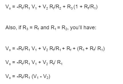
In addition, it’s crucial to note that you can modify this circuit to produce different designs like an instrumentation amplifier, Wheatstone bridge differential amplifier, etc.
And you can use these devices as servo controllers, automatic gain controllers, analog multipliers, amplitude modulators, etc.
Furthermore, you can cover various applications like myriad applications, instrumentation systems, and analog-to-digital converters.
The Bottom Line
In closing, we’ve seen the effectiveness of the BJT differential amplifier in an integrated circuit.
The device is perfect for amplifying tiny signals between two inputs.
Plus, it does a great job stopping common-mode calls for both inputs.
Interestingly, the BJT and OP-amp differential amplifiers can achieve the same results. But they work with transistors and resistors, respectively.
With the schematic design of the Bipolar junction transistor shown here, you can easily design your circuit.
So, tell us, could we answer all your questions concerning the subject? Let us know!
But if you still have challenges understanding the BJT, please reach us.
Special Offer: Get $100 off your order!
Email [email protected] to get started!