Making a transistor radio circuit is undoubtedly easy. With the PCB design and other components, you can assemble portable radios in a few minutes. Besides, if you don't have all the features of transistor radios, you can use simple materials in the home. Generally, to receive radio reception, you'll need a band selector, an antenna stage, a receiving entity, and of course, an amplifier stage.
The circuit of the commercial transistor radio in this article is quite simple. But, it has all stages to make a radio shack receive a signal. However, the simplicity of the radio circuit construction allows it only to receive and select strong stations. No doubt, you may find it annoying, especially if several active stations are jamming around the electronic communication device.
Contents
- 1. What is Transistor Radio?
- 2.How to make a transistor radio?
- 2.1 Materials
- 2.2 Circuit diagram design
- 3. Steps for Make a Transistor Radio
- Step 1: Prep your materials
- Step 2: Create the primary tuning circuit
- Step 3:
- Step 4:
- Step 5:
- Step 6:
- Step 7:
- Step 8:
- 4.How A Transistor Radio Circuit Works
- Note:
- Circuit Operation skills
- Headphones as both the switch and load
- Conclusion
1. What is Transistor Radio?
A transistor radio is an actual radio that uses transistor-based circuits. Just like any audio amplifier, it picks up signals and plays music. Moreover, you can listen to the compact transistor radio over headphones. After the invention of transistors in 1947, radio manufacturers made Regency TR-1 radios as the 1st edition.
Today, people use the all-transistor car radio to listen to the news. However, over time, digital devices with better audio output replaced the cheap AM transistor radios. But in 1959, many Japanese companies began to mass-produce billions of transistor radios. Therefore, making them the first commercial transistor radio.
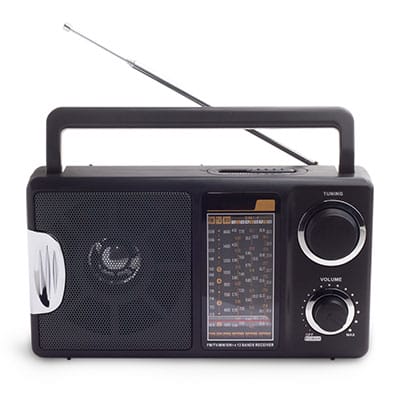
(transistor radio)
Special Offer: Get $100 off your order!
Email sales@ourpcb.net to get started!
2.How to make a transistor radio?
To build a transistor radio circuit, gather components such as an MW antenna coil, a 1-1.5V battery, a variable capacitor, an NPN transistor, a 10-ohm resistor, and connecting wires. Assemble the circuit by connecting the antenna coil and variable capacitor to form the tuning section, then integrate the transistor and resistor to amplify the received signals, allowing audio output through headphones.
Below is a circuit diagram as well as the materials of the simple TR-1 radio. It uses a single transistor as the active component.
2.1 Materials
- MW Antenna coil
- 1- 1.5 V Battery
- Variable capacitor
- Pine board
- Battery foil
- Battery holder
- Cable wires for electronic circuits
- Drill to make holes
- Safety pin
- 1- 10 ohms resistor
- NPN Transistor
- Penny (for a penny-powered radio)
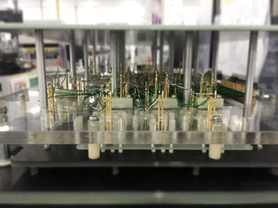
(antenna coil)
2.2 Circuit diagram design
The diagram shows the design of a typical antenna coil for receiving radio reception. It also shows the tuning capacitor at the upper end. Plus, there’s a transistor at the center. In the figure, you’ll further see the battery clip and coil wires connected to the variable capacitor at the sides. Finally, you’ll notice the open speaker at the bottom with the earphone jack.
With a closer look, you’ll again see the measurement of each piece of wire connecting. The penny-powered radio circuit is undoubtedly similar to the regular transistor radio circuit. However, it has a penny connected to the earphone.
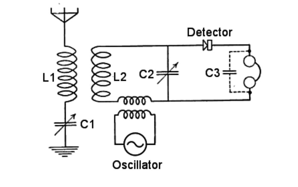
https://en.wikipedia.org/wiki/Radio_receiver#/media/File:Heterodyne_radio_receiver_circuit_1920.png (transistor radio circuit)
3. Steps for Make a Transistor Radio
Follow these steps to build a prototype transistor radio.
Step 1: Prep your materials
Get a section of PCB board for your wooden base. Assemble the other components of transistor radios, such as copper 28-AWG wire, with an electronic communication device. But if you're not familiar with the 28-AWG wire system gauging, it's 0.013 inches in diameter.
Step 2: Create the primary tuning circuit
Make a hole in the tube at ½ inch from one end to another. Thread the free side of the blue wires through the other end of the line. Next, wrap the piece of wire around the tube without it overlapping. Continue the process for about 120 turns before making two holes again— at the opposite ends. To finish this stage, solder a few short wires. And use the appropriate diameter length of the hole to the variable capacitor and coil.
Step 3:
Fabricate the tuning capacitor. Then carefully save the aluminum foil and cellophane. Flatten these materials by trimming them to a small size. Place them at the center of the wood and tape each side to it.
Step 4:
Place the antenna coil at the actual 2- 0.1 uF ceramic capacitor. Hold it to the board with pins. After that, remove the enamel insulation on the wire and pin it to the foil edge.
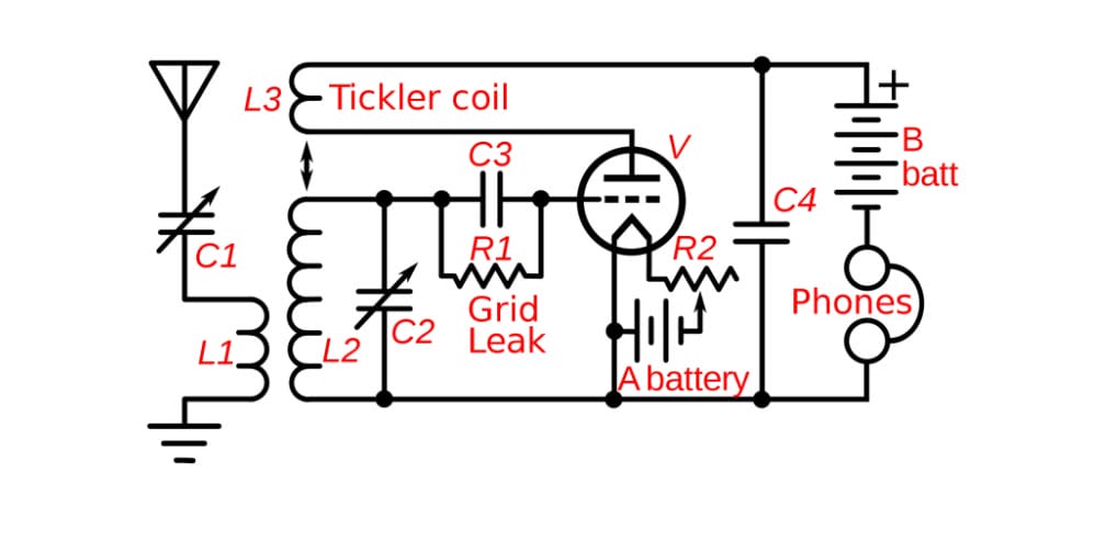
https://en.wikipedia.org/wiki/Radio_receiver#/media/File:Armstrong_regenerative_receiver_circuit.svg (Regeneration receiving circuit)
Step 5:
Ensure you have an excellent electrical connection before overlaying the foil with the cellophane. Then hold it in place and insulate the iron.
Step 6:
Complete the variable capacitor by pulling apart the second cigarette. Save the foil and pin it over a different pine board piece. Then place a tip of the wire under any of the four safety pins and anchor the opposite sides to the remaining coil wire.
Step 7:
Mount the antenna coil and the variable capacitor on the board. Next, power it using a single 1.5V battery. Then place the battery holder on the board to work as an on/off switch or headphones.
Step 8:
The audible output will be available at the variable capacitor. With it, you can listen to music using high impedance headphones. Keep in mind that the radio will not work in places with extreme shortwave radio signals.
4.How A Transistor Radio Circuit Works
Note:
- You can power the primary tuning circuit from a 3V or 22-volt battery.
- The antenna coil can be 2m long.
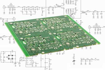
- Ideally, you construct the circuit on a PCB board.
- Ensure the headphone has a high impedance (2k to 3k type).
- You can tune these portable radios by regulating the variable capacitor.
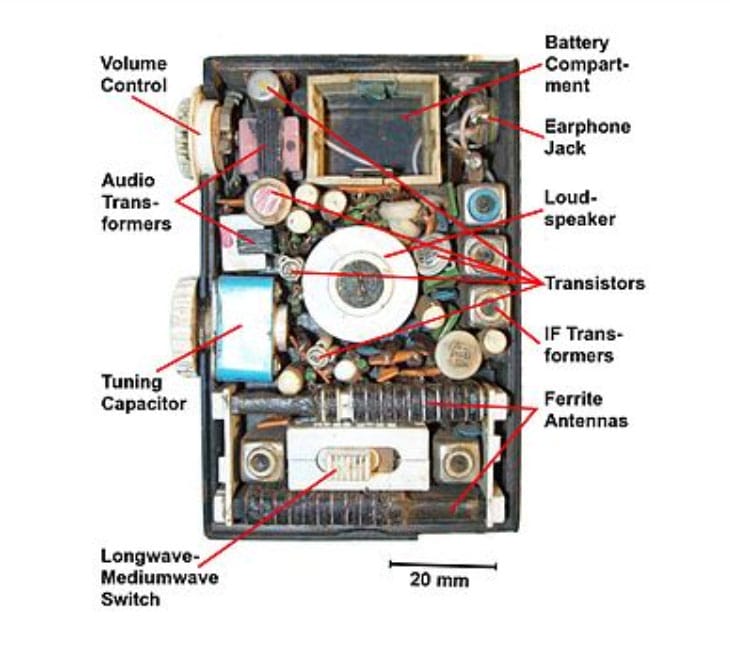
https://en.wikipedia.org/wiki/Transistor_radio#/media/File:Pocket_radio_open_english.jpg (Soviet radio orljonok back cover open, display parts)
Circuit Operation skills
From the circuit diagram, you’ll notice it has a single transistor alongside other passive components. Moreover, the coil also tunes with a GANG condenser or a 1-variable capacitor. These elements connect parallel to the coil wire. The loop alongside the capacitor also forms a resonant tank circuit. At a setting, the loop locks on to the resonant frequency.
An external power signal from the tuning capacitor then goes to the transistor base. The power works as both amplifier elements and demodulators. Furthermore, the air tuning capacitor at the bottom of the transistor ensures that only radio information passes through the transistor. At the same, it blocks the DC element from the supply.
Headphones as both the switch and load
When you apply the amplified signal and the demodulator, your headphones work as the collector of the transistor load. By connecting them, you'll distinctly hear calls from the radio shack over the headphones.
Plugging in the earphones begins the circuit operation. And whenever you unplug your earphones, it immediately goes off. By using the headphones as a switch, you bypass the need for additional control. Therefore, making the circuit compact.
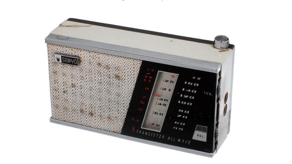
https://en.wikipedia.org/wiki/Transistor_radio#/media/File:Sanyo_Transistor.jpg (Transistor radio, receiving AM and short wave band)
Conclusion
Building a transistor radio is both an enjoyable and challenging process. At first, it may take you a while to find a good amplifier or an excellent reception. But, by following the circuit diagrams, you’ll eventually be able to listen to BBC radio and other stations.
Now, you can build a transistor radio that uses entirely cheap elements without external power. If you have other questions, please feel free to contact us.
Special Offer: Get $100 off your order!
Email sales@ourpcb.net to get started!