If you are conversant with the working of computers, you understand they use a binary digit system. Also, in a digital circuit, a binary digit system is made of adders.
Therefore, if you are keen on understanding the arithmetic circuits, you should know the workings of adders. Typically, we have two main types of adders that combine binary inputs, including the full adder vs half adder.
In this article, we'll compare full adder vs half adder circuits, and Additionally, we'll highlight their truth table and similarities. Hence, keep reading for more insights on adders.
Contents
- What is Full Adder?
- What is Half Adder?
- Truth Table of Full Adder
- Truth Table of Half Adder
- Carry Lookahead Adders
- Similarities and Differences Between Full Adder vs. Half Adder
- Similarities
- Differences
- Pros and Cons of Full Adder vs. Half Adder Full Adder
- Half Adder Pros
- Full Adder Pros
- Half Adder and Full Adder Cons
- Application of Full Adder vs. Half Adder
- Conclusion
What is Full Adder?

Figure 1: An illustration of a Digital Processor
It is a logic circuit with three inputs: an OR gate, 2 AND logic gates, and 2 EX-OR logic gates. It is a combinational circuit, which means it does not feature a storage property.
Nonetheless, it features additional logic gates that fit complex arithmetic operations.
It is also a multibit adder capable of adding two one-bit binary numbers. The multibit operation enables the addition of several input digits to create a series.
Hence, it is also a ripple-carry adder.
In the adder module, you will find the first two inputs as A and B in most circuits. The third input is an additional carry-in (Cin) input.
C-out represents the output carry for the outputs, while S or SUM represents the standard output.
In this case, the input carry represents what the circuit had in the previous carry.
Therefore, the complete adder circuit combines the three input bits to give two outputs, one of which is the standard output, while the other is the output carry.
You can also create a full adder using a single OR gate and two half adders.
Note that you will obtain the equation at the EX-OR gate when you add the binary digits.
On the other hand, the output from the AND gate is the effect of adding the carry.
Here is the Boolean expression of the C-out: AB + BC + AC.
The C in this equation represents the Carry-in input, ideally the previous carry input.
What is Half Adder?

Figure 2: A Man Using a Calculator
Like the full adder, a half adder is also a combinational logic circuit. However, unlike the full adder with three inputs, a half adder only comprises an EX-OR gate and an AND gate.
It is a 1-bit adder that will add the two input bits.
It comprises two input terminals, A and B, and two output terminals.
One gate output is the half-adder sum output, while the other is the half-adder carry output.
The EX-OR gate will provide an output, a sum of two input values.
Nonetheless, for the half adder, the carry-in one addition does not reflect in the next addition.
Ideally, the cause of this is a lack of a logic gate to facilitate the operation.
Hence, it derives the name half-adder circuit as it lacks the full-adder characteristics.
Here is the equation for the logical operation of the two-bit output circuit.
S = A + B. The sum is the addition of the two inputs.
On the other hand, the Carry (C) for the half adder is A x B.
Truth Table of Full Adder
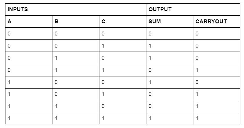
Figure 3: A Full Adder Truth Table
We can create the logical expression for sum and carry output from the above truth table.
We have already explained the two equations above.
Consequently, the final Boolean expression for the above truth table is
C (out) = AB + A(Cin) + B(Cin)
Here are the necessary deductions from the truth table:
- The combinations that result in ones will give a high sum output. Such varieties include 010, 001, and 100. The sum output is high when there is only one high at the second XOR gate.
- The result is a low sum and high carry-out for the combinations that lead to a two. They include 101, 110, and 011.
Truth Table of Half Adder

Figure 4: A Half Adder Truth Table
Special Offer: Get $100 off your order!
Email [email protected] to get started!
Carry Lookahead Adders

Figure 5: An Illustration of the Binary System
They are fast adders that improve the time of deciphering the carry bits in digital electronics. A carry-lookahead adder is different from the typical ripple carry adder.
In logic operations of the latter, the sum bit and carry bits require simultaneous calculation.
However, each calculation has to wait for the other to end so that the other one commences. The Carry lookahead adders seek to solve this lengthy process.
Carrying lookahead adders leads to a significant aggressive reduction in the wait time for calculations.
The reduction process is possible as these adders calculate more than one carry bit before the sum. Also, the bits to be added are available immediately.
Ideally, these adders do not have to await the arrival of the carry from the former black.
Hence, the carry-lookahead adders can handle 4-bit blocks faster than the typical one-bit full adder.
Similarities and Differences Between Full Adder vs. Half Adder

Figure 6: An Illustration of a Complex Mathematical Expression
Similarities
- Both the full adder and half adder are combinational digital circuits. Unlike sequential circuits, the two lack a memory perspective.
- They both provide a means of performing arithmetic operations. Any arithmetic circuit will, therefore, feature one of them.
Differences
- The half-adder will add two binary inputs to give out a carry and a sum. On the other hand, the full adder will add three binary inputs to generate the carry and sum. Hence, there is a significant difference in their hardware architectures.
- The carry from the previous addition is inconsequential in half adder as it does not add to the next step.
- On the other hand, in the full adder digital logic, the carry from the previous step is helpful in the subsequent addition.
- There are two logic gates in the half adder: the EX-OR gate and the AND gate. The full adder features three logic gates: an OR gate, three AND gates, and two EX-OR gates.
- The half adder consists of two input bits, A and B, while the full adder features three input bits. In addition to the A and B, there is an additional C input bit.
- The carry equations of the two adders are also different. For the half adder, the Sum = A + B, and C = A x B. For the full adder, the Sum = A + B + Cin and C A x B + Cin (A + B).
Pros and Cons of Full Adder vs. Half Adder Full Adder

Figure 7: A Calculator
Half Adder Pros
- The adder facilitates the addition of two single-bit numbers in digital arithmetic operations.
- It is also easy to design.
Full Adder Pros
- They facilitate adding the carry from the previous operation, and half-adders cannot perform such an action.
- The full adder is essential in creating critical circuits such as multiplexers.
- The power consumption by the full adder is relatively less than for the half adder circuits.
- Adding an inverter to the full adder will facilitate the creation of a half subtractor.
- A full adder will also give a higher output than the half adder, allowing more combinations to facilitate increased work.
- The speed of the full adder during applications is also relatively higher than that of the half adder.
- The full adder is also strong enough to support voltage scaling.
Half Adder and Full Adder Cons
- The half-adder is not fit for carrying the addition of the previous operation since it has two inputs. Hence, it will not apply in conducting multibit operations.
- When the full adder is in the form of a ripple adder, the output drive capability diminishes.
Application of Full Adder vs. Half Adder

Figure 8: A Binary Numbers Illustration
- The half adder can be applicable in the creation of complete adder combinations.
- Full adders are useful in Arithmetic Logic Unit (ALU) systems.
- The binary addition property of half adders is applicable in the working of calculators.
- Full adders are helpful in various forms of digital circuits and digital electronics.
- The adders are also helpful in carrying out multiplication.
- Full adders are applicable in the generation of memory addresses and the creation of program counterpoints.
- The Full adders are essential in creating complex circuits capable of adding numerous bits simultaneously.
- Full adders are critical for creating the graphical processing unit (GPU).
- Half-adders are helpful in digital measuring devices.
Conclusion
We have elaborated on the key features and differences between the full and half adder.
Both are significant in electronic digital circuits and serve different purposes, as we have explained.
We hope that you now understand every vital bit about the adders. For more information and queries, contact us; we will get back to you immediately.
Special Offer: Get $100 off your order!
Email [email protected] to get started!