Composition decides whether a solder alloy has one melting point or separate solidus and liquidus temperatures. Eutectic Sn63/Pb37 changes phase at 183°C (361°F), while Sn50/Pb50, often called 50/50 solder, starts melting at 183°C (361°F) and becomes fully liquid at 216°C (421°F). Between a non-eutectic alloy's solidus and liquidus, solid and liquid phases coexist, so the joint must remain still while cooling through that interval. Wire, paste, and bar made from the same alloy share these phase limits. See our lead vs. lead-free solder guide for broader composition and process tradeoffs.
What Temperature Does Solder Melt?
Solder does not have one universal melting point: Sn63/Pb37 melts at 183°C (361°F), while 50/50 Sn/Pb melts over 183–216°C (361–421°F).
| Alloy | Solidus °C | Solidus °F | Liquidus °C | Liquidus °F | Pasty range | Peak reflow or working guidance | Typical use |
|---|---|---|---|---|---|---|---|
| Sn63/Pb37 | 183°C | 361°F | 183°C | 361°F | 0°C / 0°F | 205–230°C / 401–446°F typical molten Sn-Pb working range | For soldering printed circuit boards where temperature limitations are critical and an extremely short melting range is required. |
| In52/Sn48 | 118°C | 244°F | 118°C | 244°F | 0°C / 0°F | Not stated in the cited sources | Step soldering |
| Bi58/Sn42 | 138°C; 139°C | 280°F; 282°F | 138°C; 139°C | 280°F; 282°F | 0°C / 0°F | Not stated in the cited sources | Step soldering |
| Sn42/Bi57/Ag1 | 137°C | 279°F | 139°C | 282°F | 2°C / 4°F | Not stated in the cited sources | Not stated in the cited sources |
| SAC305 (Sn96.5/Ag3/Cu0.5) | 217°C | 423°F | 221°C | 430°F | 4°C / 7°F | 230–250°C / 446–482°F typical SAC reflow band | Widely used lead-free PCB assembly alloy |
| SN100C (Sn-0.7Cu-0.05Ni-Ge; balance Sn) | 227°C | 441°F | 227°C | 441°F | 0°C / 0°F | Not stated in the cited sources | Not stated in the cited sources |
| Sn50/Pb50 (50/50 solder) | 183°C | 361°F | 216°C; 217°C | 421°F | 33°C / 59°F; 34°C / 60°F | Not stated in the cited sources | For general purposes. Most popular of all. Can be used for noncritical electrical soldering. |
| Sn60/Pb40 (60/40 solder) | 183°C | 361°F | 190°C; 188°C | 374°F; 370°F | 7°C / 13°F; 5°C / 9°F | Keep the joint still through the plastic range | Electrical and electronic connections and coating metals |
| Sn40/Pb60 (40/60 solder) | 183°C | 361°F | 238°C; 235°C | 460°F; 455°F | 55°C / 99°F; 52°C / 94°F | Not stated in the cited sources | For dip soldering and as a wiping solder for joining lead pipes and cable sheaths. |
| Sn96.5/Ag3.5 | 221°C | 430°F | 221°C | 430°F | 0°C / 0°F | Not stated in the cited sources | Not stated in the cited sources |
| Sn5/Pb95 | 308°C; 300°C | 586°F; 572°F | 312°C; 314°C | 594°F; 596°F | 4°C / 7°F; 14°C / 24°F | Not stated in the cited sources | For coating and joining metals. |
Equal solidus and liquidus values mark one phase-change point; a range is not reduced to its midpoint. Because both Fahrenheit endpoints are rounded, a calculated span can differ by one degree from subtracting those endpoints. A span printed by a source is transcribed rather than recalculated. The Welding Handbook forms each range from its own endpoints in each unit, so its 14°C span is paired with the 24°F it prints rather than the 25°F a conversion would give. Where a source prints one unit, the table converts the other and keeps the same reference. “Not stated in the cited sources” means that the listed references give no value or guidance for that field.


At Sn63/Pb37, the chart curves meet at 183°C (361°F); their gaps are 33°C at Sn50/Pb50 and 55°C at Sn40/Pb60. The chart plots the 2 to 70 percent tin entries in the ASTM B32-08 (R2014) table reproduced in Machinery's Handbook, 31st edition; the wider tin-lead system continues beyond 70 percent. Sn35/Pb65 is omitted because its printed 447°F liquidus falls below the neighbouring 460°F for Sn40/Pb60 and 491°F for Sn30/Pb70, while the Welding Handbook gives Sn35/Pb65 as 477°F. For Sn5/Pb95, the chart uses the 308°C converted from the Machinery's table, while the Welding Handbook prints 300°C.
What Is the Melting Temperature of Lead?
Pure lead melts at about 327.5°C (621.5°F), but lead solder is an alloy and melts much lower. Sn60/Pb40 solder starts melting at 183°C (361°F) and becomes fully liquid at 190°C (374°F). Do not substitute the pure-lead value for a lead-solder value.
| Pure element | Symbol | Melting point °C | Melting point °F |
|---|---|---|---|
| Tin | Sn | 231.9681°C | 449.5°F |
| Lead | Pb | 327.502°C | 621.5°F |
| Silver | Ag | 961.93°C | 1,763.5°F |
| Copper | Cu | 1083.4 ± 0.2°C | 1,982.1 ± 0.4°F |
| Bismuth | Bi | 271.3°C | 520.3°F |
| Indium | In | 156.61°C | 313.9°F |
What Is the Soft Solder Melting Temperature?
Soft solder is a category of filler alloys used below 450°C (about 840°F), not one alloy with one melting point. Electronics examples range from In52/Sn48 at 118°C (244°F) to high-lead soft solders above 300°C (572°F), but the alloy label still controls the actual solidus and liquidus.
| Joining process | What melts | Temperature discriminator | PCB meaning |
|---|---|---|---|
| Soft soldering | Only the filler alloy melts | Below 450°C (the handbook prints 840°F; exact conversion is 842°F) | Normal category for electronic assembly |
| Brazing | Only the filler alloy melts | Above 450°C (about 840°F; exact conversion is 842°F) | Often called hard soldering; generally too hot for PCB materials and parts |
| Fusion welding | The base-metal surfaces melt; filler is optional | Defined by melting the base metal, not by the 450°C / 842°F filler boundary | Not the process used to make an electronic solder joint |
What Is the Silver Solder Melting Temperature?
“Silver solder” can mean either a silver-bearing soft solder or a silver brazing alloy, and their temperatures are hundreds of degrees apart.
- Silver-bearing soft solder: eutectic Sn96.5/Ag3.5 melts at 221°C (430°F). It remains below the soldering-to-brazing boundary.
- Silver brazing alloy: TM 9-237-1, printed page 2, gives FS-BCuP-5 a melting point of approximately 1,200°F (about 649°C) and a melting-temperature span of approximately 300°F (about 167°C). It is a brazing filler, not PCB solder.
Always ask for the alloy designation. The word “silver” alone does not identify a usable iron, torch, or reflow temperature.
Working Temperature vs. Melting Temperature
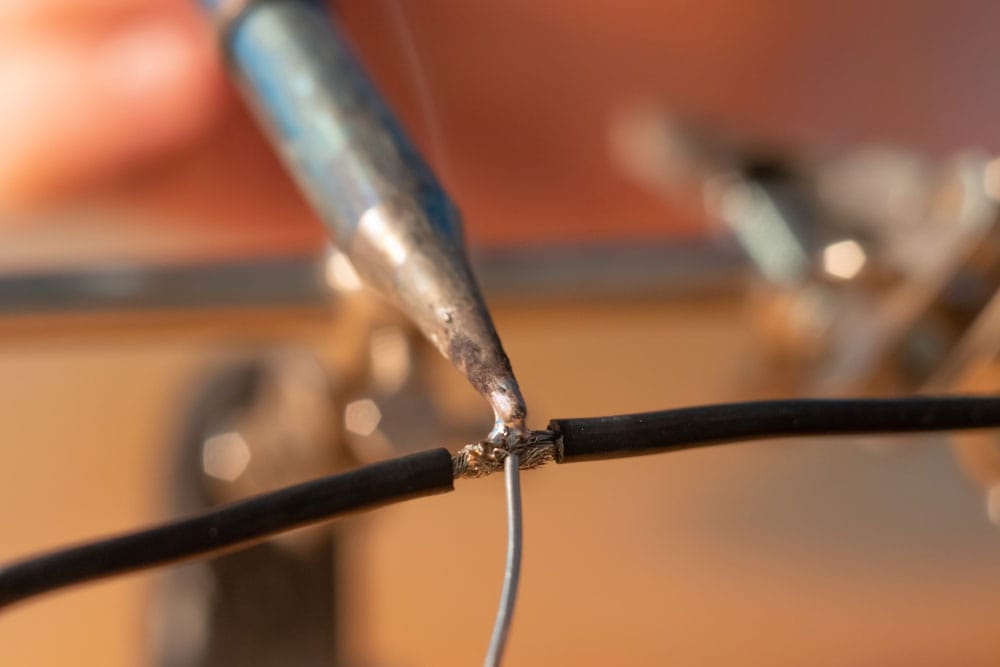
The melting temperature belongs to the alloy; the working temperature belongs to the process. A joint, iron, solder pot, or oven needs thermal margin above liquidus so every surface reaches a wetting temperature despite heat loss and different component masses. That margin is why an Sn63/Pb37 joint melts at 183°C (361°F) while an iron can be set near 350°C (662°F).
| MIL-STD-202H simulation | Condition °C | Condition °F | Exposure | Temperature refers to |
|---|---|---|---|---|
| Soldering iron, condition A | 340–360°C | 644–680°F | 4–5 s | Iron-tip temperature |
| Dip solder, condition B | 255–265°C | 491–509°F | 9–11 s | Molten-solder temperature |
| Wave solder, conditions C and D | 255–265°C | 491–509°F | 19–21 s topside; 9–11 s bottomside | Molten-solder temperature |
| IR/convection reflow, conditions I, J, and K | 210–220°C; 230–240°C; or 245–255°C | 410–428°F; 446–464°F; or 473–491°F | 90–120 s above 183°C; 25–35 s at the final condition; 3 heat cycles | Measured component temperature |
Choose the alloy first, then qualify the lowest process temperature that provides complete wetting without exceeding the board or component limits. Do not copy an iron setting into a reflow profile.
Sn63/Pb37 becomes liquid at 183°C (361°F). The Printed Circuits Handbook gives a typical molten Sn-Pb working range of 205–230°C (401–446°F). MIL-STD-202H Method 210, Table I, printed page 6, specifies a soldering iron at 350 ±10°C (662 ±18°F) applied for 4–5 seconds. That last figure is a resistance-to-soldering-heat test condition, not a recommended production setting, so qualify your own process.

Special Offer: Get $100 off your order!
Email sales@ourpcb.net to get started!
What Is Solder?
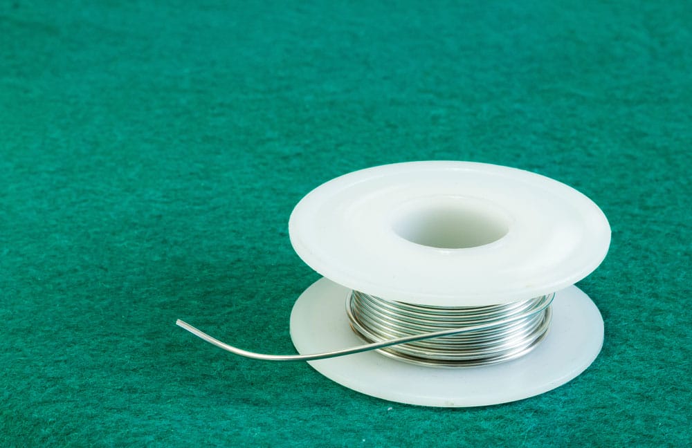
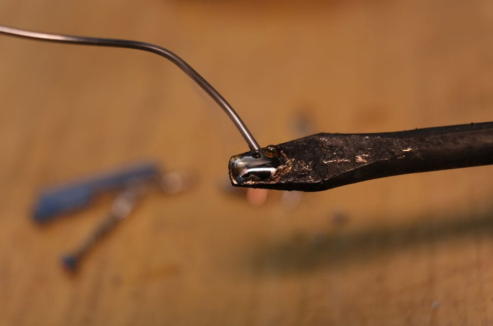
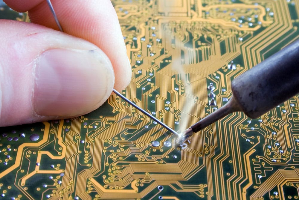
Solder is a filler-metal alloy that joins adjacent surfaces without melting the base metal. In electronics, the molten alloy must wet the component termination and printed circuit board (PCB) pad, then solidify into an electrical and mechanical connection.
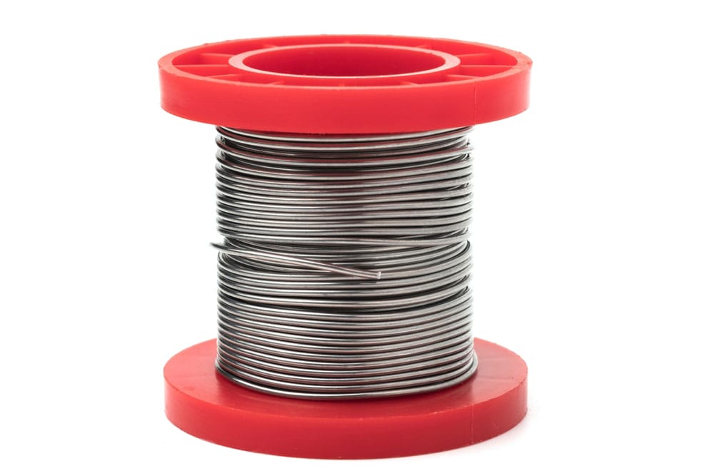
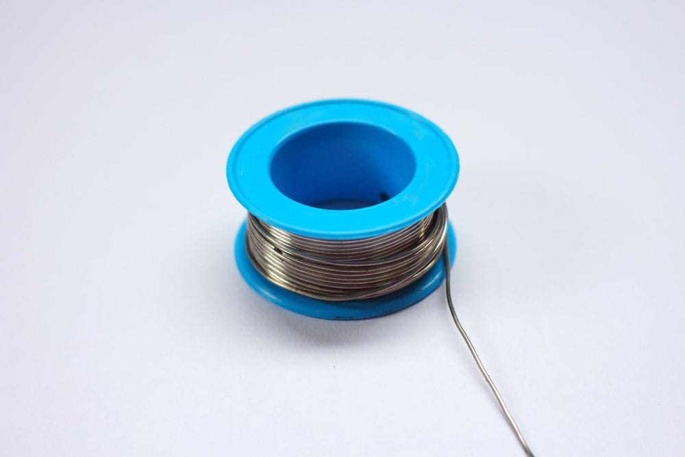
Composition determines whether the alloy changes phase at one temperature or across a solidus-to-liquidus range. Form does not change that alloy temperature: wire, bar, and paste made from the same alloy share the same phase limits.


Eutectic vs. Non-Eutectic Solder
Eutectic solder
A eutectic alloy has one transition temperature, so its solidus and liquidus are equal. Sn63/Pb37 changes from solid to liquid at 183°C (361°F) with no pasty range. That fast transition and predictable wetting made it the traditional reference alloy for PCB assembly.
Non-eutectic solder
A non-eutectic alloy first softens at its solidus and becomes fully liquid only at its liquidus. Between those limits, solid and liquid phases coexist as a paste or slush. For Sn60/Pb40, NEETS Module 14 prints a 183–188°C (361–370°F) plastic interval on printed page 2-20, while the ASTM B32 table reproduced in Machinery's Handbook prints 183–190°C (361–374°F) on printed page 1567. The 50/50 solder interval is 183–216°C (361–421°F) in that ASTM table.
Movement during this window can leave a damaged or disturbed connection. Hold the work still until it cools below the solidus. This practical penalty is why eutectic Sn63/Pb37 was preferred for hand soldering when leaded solder was permitted.

High-Temperature vs. Low-Temperature Solder
“High” and “low” are relative to the assembly and to the earlier soldering step. The exact alloy range matters more than the label.
High-temperature solder
High-lead alloys are used when a joint must survive a later, lower-temperature joining step or elevated service. Coombs's Printed Circuits Handbook, printed page 979, gives high-lead Sn10/Pb90 a solidus of 268°C (514°F) and a liquidus of 302°C (576°F).
Printed Circuits Handbook, printed page 979, gives 5Sn/95Pb as 301–314°C (574–597°F), while the ASTM B32 table reproduced in Machinery's Handbook, printed page 1567, gives 308–312°C (586–594°F). The sources report different phase ranges for this nominal alloy. High-lead reflow processing can damage organic PCB laminate, so qualify materials and the full thermal profile.
Select a high-temperature alloy against the actual service temperature, substrate, finish, and later joining steps. Not every solder contains tin, and a higher tin percentage alone does not guarantee better wetting; the alloy, flux, surface finish, oxide condition, and thermal process all matter.

Low-temperature solder
Verified electronics examples include eutectic In52/Sn48 at 118°C (244°F). For eutectic Bi58/Sn42, Coombs reports 138°C (280°F), while IPC-7095A reports 139°C (282°F). These alloys support step soldering and reduce heat exposure during assembly or repair.
Mixtures that melt this far below tin-lead sit among the fusible alloys, which are related low-melting alloys rather than a sharply separate family. American Machinists' Handbook, printed pages 91–92, says the exact point of separation between a fusible metal and a non-fusible one is very uncertain, and its table of solders and fusible alloys reaches down to an entry the handbook prints as 66°C and 150°F. Adding bismuth lowers the melting point, and adding cadmium lowers it further still. No very low figure selects a PCB solder on its own: you need the identified alloy and its supplier data sheet.
- Mounting components on flexible PCBs
- Mounting temperature-sensitive components
- Step or second-side PCB soldering to avoid disturbing standard lead-free solder joints or removing soldered components.
- Repair where a lower thermal load reduces the risk of pad or barrel damage
A lower qualified reflow temperature can reduce assembly heat exposure and energy use. It does not, by itself, prove that equipment will last longer; maintenance, duty cycle, and machine design also control service life.

For production help with alloy compatibility and thermal profiling, review OurPCB's PCB assembly capabilities.
Solder Blends
Solder is a metal alloy, and flux is a separate chemical aid rather than one of its metals. Alloys range from two metals, as in Sn63/Pb37, to three or more, as in SAC305. Alloy additions change phase behavior, wetting, strength, oxidation, and interactions with board finishes, but the effect depends on the complete composition.
- Bismuth and indium: enable verified low-temperature alloys, including Bi58/Sn42 at 138°C (280°F), per Printed Circuits Handbook printed page 982, and In52/Sn48 at 118°C (244°F), per IPC-7095A printed page 94.
- Copper: forms the 227°C (441°F) Sn-Cu eutectic near 0.7% copper, but excess copper can make a solder pot sluggish and raise its phase-change range.
- Antimony: can increase tensile strength in specific tin-antimony formulations, but the effect changes with concentration and service temperature. It is not a universal strength upgrade.
- Silver: appears in both 221°C (430°F) Sn-Ag soft solder and much hotter silver brazing alloys. In Sn-Pb solder, a small silver addition can slow dissolution of a silver finish and can improve wetting.
- Nickel and germanium: are trace additions in the supplier-specified SN100C alloy, per Recent Progress in Soldering Materials printed pages 95–96. Separately, nickel plating can protect underlying copper because nickel dissolves more slowly in molten Sn-Pb solder. That barrier role belongs to the surface-finish stack, not automatically to trace nickel inside every solder alloy.
See our lead vs. lead-free solder guide for the wider material-selection tradeoffs.
Other Factors To Consider When Choosing Solder
Besides composition (which determines the melting temperature), consider these two factors before buying wire solder.
Solder Wire Diameter and Selection
Soldering wire melts at the solidus and liquidus of its alloy, not at a temperature set by the wire diameter. Sn63/Pb37 wire melts at 183°C (361°F). For Sn60/Pb40, NEETS Module 14 prints 183–188°C (361–370°F) on printed page 2-20, while the ASTM B32 table in Machinery's Handbook prints 183–190°C (361–374°F) on printed page 1567. A flux core does not change those metal phase limits.
Electronics wire solder usually has a diameter ranging from 0.5-1.5mm (some are even narrower than 0.5mm). Always match this diameter to the contact and connector size you want to solder. If the wire is too broad, you'll have a difficult time trying to maneuver around components on a dense PCB. This difficulty will increase the chances of thermal stressing or welding parts that don't require soldering. On the other hand, if the wire is too thin, you'll burn through the solder quickly.
Solid Wire or Flux-Core Solder
Solid wire contains alloy only, so you apply a compatible flux separately. Flux-core wire carries rosin or another specified flux inside the metal wire. As the alloy melts, the flux removes oxide films, limits renewed oxidation, lowers interfacial tension, and helps the solder wet.
For electronics, use a flux intended for electrical assembly. A flux core does not eliminate initial surface preparation. The required residue cleanup depends on the flux specification. It changes application and cleanup, but the alloy designation still determines melting temperature.

Summary
Solder melting temperature always belongs to a named alloy. Sn63/Pb37 has one 183°C (361°F) transition. For 60/40, NEETS Module 14, printed page 2-20, gives 183–188°C (361–370°F), while the ASTM B32 table in Machinery's Handbook, printed page 1567, gives 183–190°C (361–374°F). The same ASTM table gives 50/50 as 183–216°C (361–421°F). Pure lead's 327.5°C (621.5°F) point is not the melting temperature of lead solder.
Read solidus and liquidus before choosing an alloy, then qualify the iron, pot, wave, or reflow profile separately. Keep a non-eutectic joint still throughout its pasty range.
Special Offer: Get $100 off your order!
Email sales@ourpcb.net to get started!