The truth is producing a flashing LED circuit is not difficult, and it is like a programmer's "Hello World." You are only looking at the electronic version of things instead. A flashing LED circuit is probably the simplest electronic circuit for beginners to build. For a simple flasher circuit diagram, you need a LED. Throw in a few other electronic components, and you're all set. The aim is to make the LED in the flasher circuit blink. Here, we look at some examples of the flasher circuit diagram and its applications. Also, you'll learn how to build various flasher circuit projects.
Contents
1. What Is The Use Of A Flasher Circuit?
A variety of applications use this simple circuit. With an electric lamp flasher, you can build several electronic circuits such as:
- Lightning detector.
- Low battery indicator.
- Micropower high supply voltage.
- Police Siren.
- Windscreen wiper controller.
- Off-line switching power supply.
- Capacitance probe.
- Lamp dimmer.
- Beeping capacitance probe.

(LED of Police Siren )
Special Offer: Get $100 off your order!
Email sales@ourpcb.net to get started!
2. How To Build an LED Flasher Circuit
There are various methods to build an LED flasher circuit. You have the option of using a relay or transistors, and other components like a microcontroller or 555-Timer chip or inverter are also viable alternatives.
Below is a step-wise guide on how to build a primary flasher circuit using the components mentioned above.
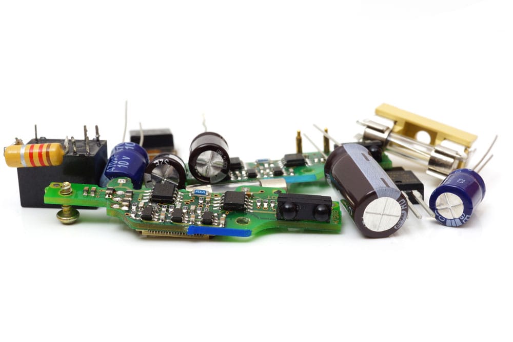
(Various components for building a PCB)
2.1 Blinking an LED Using Relays
In this type of circuit, applying power triggers the battery to charge the capacitor. Although this charge first passes through the resistor R2.
In this short time, the Relay goes into the opposite position, and this pull from the relay coil turns the LED into an ON state.
When the capacitor discharges, the Relay returns to its initial state. In effect, the LED goes OFF.
The cycle then goes on, over and over. This loop brings about the blinking effect.
This easy-to-build circuit needs a few components to set up. They include:
- (5-12)V power supply.
- A 6V Relay.
- A 1000 µF capacitor.
- 2.2KΩ resistor.
- Any LED of the desired color.
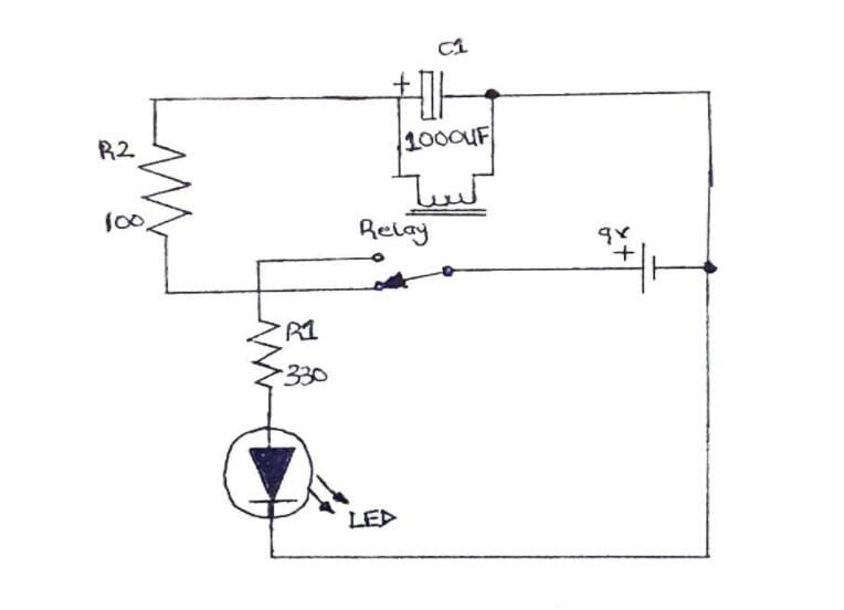
(Flasher Circuit Diagram using a relay)
The Steps To Follow
First, connect the LED to the resistor by soldering the metallic strips together. Make sure to solder the ohmic resistor to the negative terminal of the LED.
Next, you will be connecting the Relay's coil-1 to the standard pin by soldering.
Afterward, install the capacitor by connecting its positive terminal to the coil-2 of the Relay. The other end then goes to the standard pin on the Relay.
You now solder the positive terminal of the capacitor to the corresponding leg of the LED.

( LED )
Then solder the negative strip of the LED and the resistor to the open relay pin.
The final step is to connect your wire with a DC power supply to the LED circuit. The power supply is preferably set below 12V.
Connect the positive wire of supply voltage to the positive leg of the LED. The negative part goes to solder with the normally closed relay pin.
At this point, your circuit is ready. So, switch on the power source and observe the blinking LED.
(Blinking and Flashing a LED Using 6V Relay)
2.2 Blinking Two LEDs Using Transistors
Here is another type of flasher LED circuit. Engineers also call it the Astable Multivibrator.
The conventional transistor LED circuit is a "two-wire" flasher. You can set it up by connecting the battery and load in series.
To build a dual-LED flasher with transistors, you need to control current and voltage with capacitors, resistors, and diodes. Nonetheless, the parts you'll need for this dual-LED flasher circuit include:
- Two LEDs of desired colors.
- Two BC547B transistors.
- Two resistors of 100kΩ
- Two resistors of 470Ω.
- Two capacitors of 10µF (C1 and C2).
- A breadboard.
- Some jumper wires.
- A 9V power supply.
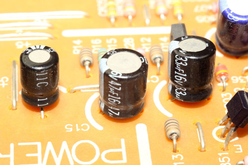
(Capacitors onboard)
The Steps To Follow
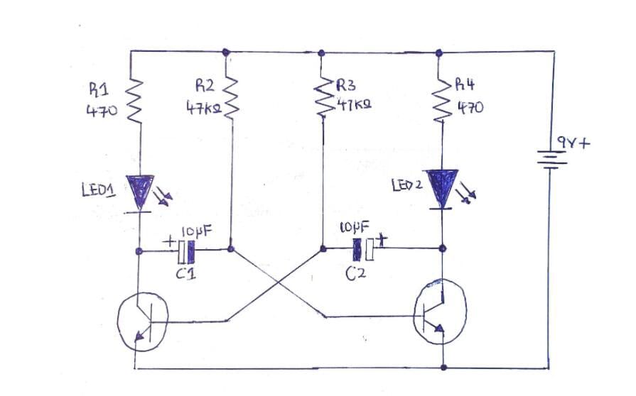
(Circuit Diagram for blinking two LEDs using transistors)
Getting started, you need first to install the transistors. You do this by connecting one end of each transistor to your power BUS jumper wires. The connection then goes to the transistors' emitters.
Next, install your capacitors. Connect the +ve end of C1 to the collector end of T2. Then, solder the -ve terminal of C1 and the base of T1 together. Repeat this same process for C2.
Then, input your 100k ohm resistors by connecting to T1 and T2. The bi-metal strip from one end of the resistor connects to the transistor's base terminal. Then you connect the opposite lead strip to the Ground. Repeat the same process for the two transistors.
Adding the LEDs comes next. You now solder the LEDs to the 470 Ohm resistors.
One wire from the first resistor goes to the collector part T1. The second resistor, you then connect to the +ve wire terminal of the first LED. After, you run the -ve end of the LED to the Ground.
Repeat the step mentioned above for the LED and the other resistor.
The last step is to supply power to the circuit. Connect the 9V supply to your LEDs and observe the flashing pulses.
At this stage, you may decide to change your capacitor ratings. With that, you can modify the dual flasher rate.
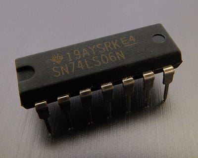
2.3 Building LED Flasher Circuit using a 555 Timer Chip
A 555 timer chip is a kind of IC that is very versatile. Using it in an appropriate connection, you can generate current pulses at different time intervals, and you specify the pulse rates with the aid of a resistor-capacitor network.
You first need to put the 555 timer chip in astable mode. That way, it can generate pulses.
The chip then switches between ON-OFF or HIGH-LOW states. This behavior is also the reason we call it Oscillator Mode. The 555 timer oscillator creates signals of square waves.
You will need a few components to set up this unique LED flasher circuit. The parts you'll need include:
- A 555-timer chip.
- A 9-volts battery or DC power source.
- Battery clip.
- Light-emitting diode (any color of choice).
- 2 Resistors of 47KΩ.
- The resistor of 470KΩ.
- A 1µF capacitor.
- Some jumper wires
- A PCB.
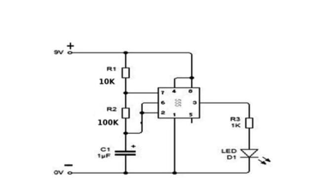
(LED circuit diagram using a 555 timer chip)
Source: https://www.youtube.com/watch?v=t8p3o5LPMOg
The Steps To Follow
The first step is to install the 555-timer IC in the PCB. Take precautions to install it right. Otherwise, connecting it to a power supply will burn the chip.
Then, use a jump wire of short length and connect the -ve IC pin ( Pin 1) to the Ground.
Next, run a connection from pin 8 to the breadboard's top row (VCC). In like manner, run a jumper wire connection between Pin 8 and Pin 4.
On the capacitor's positive terminal, connect Pin 2. Then, run the negative terminal to the Ground.
Next, use another jumper wire to connect Pins 2 and 6.
Your next step is to connect the Pins to the resistors. Connect Pins 6 and 7 to the 470k ohm resistor. Afterward, link the second resistor of 47k Ohms to Pin 7 and run it to the VCC.
One strip of the other 1k Ohm resistor goes to the Output Pin 3, and the other end goes into an empty row of the PCB.
You will then connect the resistors to the LED. The +ve terminal of the LED connects to the resistors. Then the -ve part goes to Ground.
Finally, use the battery clip to hold the battery in place. The red wire of the battery goes to the VCC, while the black goes to the Ground.
When power is supplied to the circuit, your LED will blink.
There are other ways to build LED flasher circuits. Some use the help of a microcontroller such as Arduino. Connecting blinking LEDs on an Arduino board is called an Arduino LED flasher circuit.
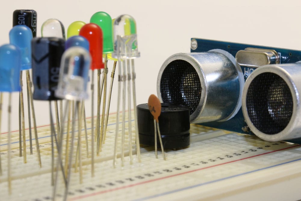
(Arduino board and other LED components)
Conclusion
There are several configurations of a lamp flasher LED circuit. The primary composition of those circuits uses passive electronic parts, including transistors, resistors, capacitors, and an LED.
However, they all work in the same principle – to cause a continuous flashing of the light-emitting diode. You can adjust the speed of the blinking light by manipulating the value of the capacitors. Or in some cases, with the help of a 555-timer IC. Thinking about building one and not sure of how to get started? Contact us for all your electronic component needs.
Special Offer: Get $100 off your order!
Email sales@ourpcb.net to get started!