The LM3914 is an integrated circuit. It is a microchip that offers a 10 step scale to expand to close to 100 segments eventually. Also, LM3914 displays an analog signal voltage.
In this article, we are going to discuss the LM3914 circuit. Our focus will be on how it works and how to use it.
Contents
What is lm3914?
Lm3914 is a monolithic integrated circuit. This circuit visually shows the magnitude of a linear analog input voltage. We get to visually see the importance of these signals from the lm3914 IC operating voltage. The IC's output can power LEDs, vacuum fluorescent lights, and LCDs.
Importantly, when using an lm3914, we need not use a single resistor. Since the current drive in the display LEDs is programmable and regulated, you need more than one resistor. This unique feature enables this IC to work with less than 3V.
Furthermore, using a single pin on the lm3914 allows you to switch the display mode from dot to graph quickly.
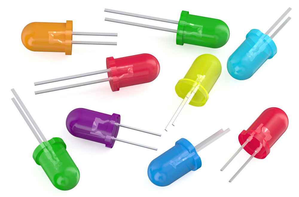
(a photo of LEDs)
LM3914 Pin Configuration
| Pin no. | Pin name | Description |
| 1 | LED 1, LED 2 up to LED 10 | You connect the 10 LEDs to these pins. |
| 2 | V- or the ground | Serves as the ground pin of the IC |
| 3 | V+ or the Vcc | This pin supplies voltage of between 3v to 18v |
| 4 | RLO | For an exact 10-step voltage divider, this pin serves as a low-level pin. |
| 5 | Signal | Serves as an analog signal input pin essentially based on the controlling of the LED. |
| 6 | RHI | This is a high-level pin for a potential divider voltage. |
| 7 | REF OUT | Pin REF OUT serves as the LED current limiting output reference voltage pin. |
| 8 | REF ADJ | Pin used to alter the voltage reference. |
| 9 | Mode | Switching between dot and bar modes is possible with this pin. |
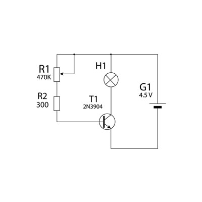
(a photo showing at-power divider)
lm3914 Specifications
- Firstly, this IC can display the output in bar and dot modes.
- Second, we can alter the voltage reference using this circuit.
- Thirdly, switching between dot and bar modes is possible with this circuit.
- Also, it has a programmable LED sink current of between 2mA to 30mA.
- In addition, we find this integrated circuit in an 18-pin DIP PLCC package.
- The IC can control 10 LEDs
- Moreover, the lm3914 IC can be advanced to drive up to 100 LED displays.
- Finally, the IC has a (3-18)v RLO low-level voltage.
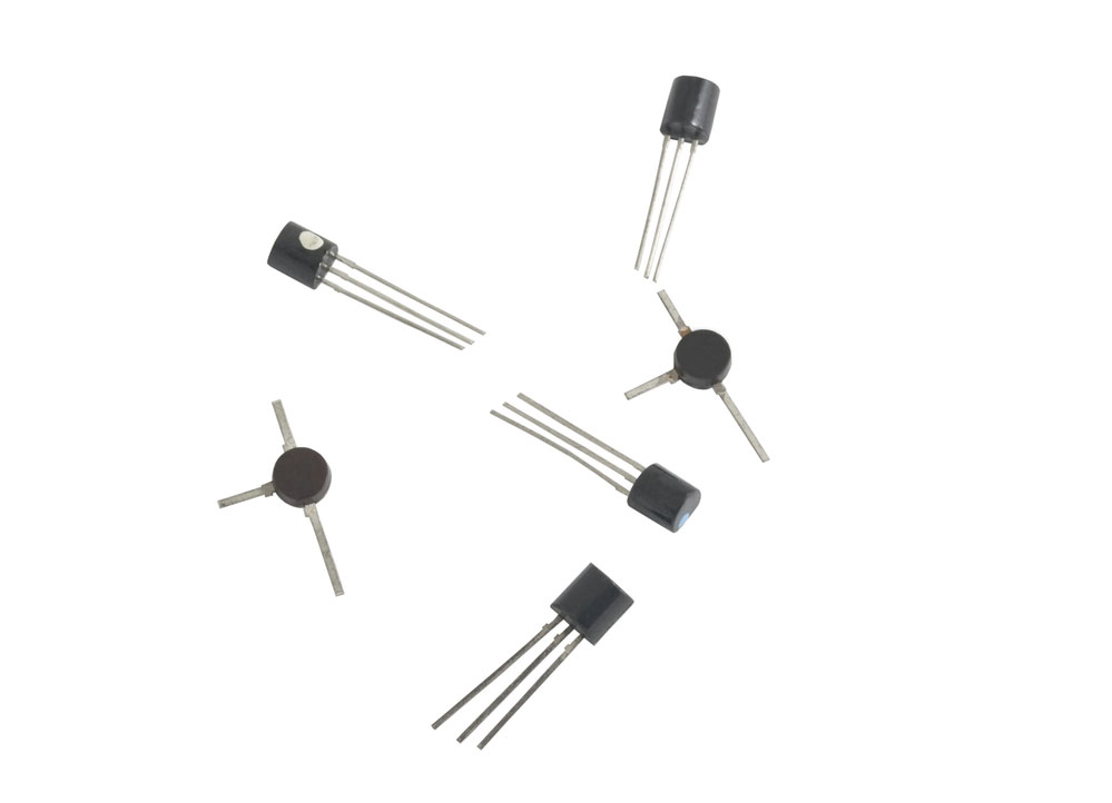
(a photo is showing transistors)
Special Offer: Get $100 off your order!
Email [email protected] to get started!
LM3914 Equivalent LED Driver
The equivalent integrated circuit to the lm3914 is the lm3916. The lm3914 integrated circuit, on the other hand, offers a variety of options. For example, these additional options might include the CD4511, MAX7219, and the CD4054.
How Does the lm3914 IC Work?
The lm3914 IC can turn on or turn off 10 LED light bulbs. This feature is why it is known as an analog-controlled LED driver. The analog input voltage determines the turning on or turning off of the ten bulbs.
There is limited use of the occasional programming and microcontroller when using the lm3914 IC. Moreover, the electronic components to control the 10 LEDs are also minimal. We have seen that the analog voltage levels are between 3v to a maximum voltage of 18v. Also, you can control the LED current by placing a single resistor on pin 7.
The interesting fact about the LM3914 circuit is that it has two electronic displays. Therefore, you can use it in either a bar or a dot display mode. Since the bar LED lights have brightness control, we use this circuit in visual alarm or monitoring applications. Additionally, do not forget that you can use more than one IC to control up to 100 light bulbs.
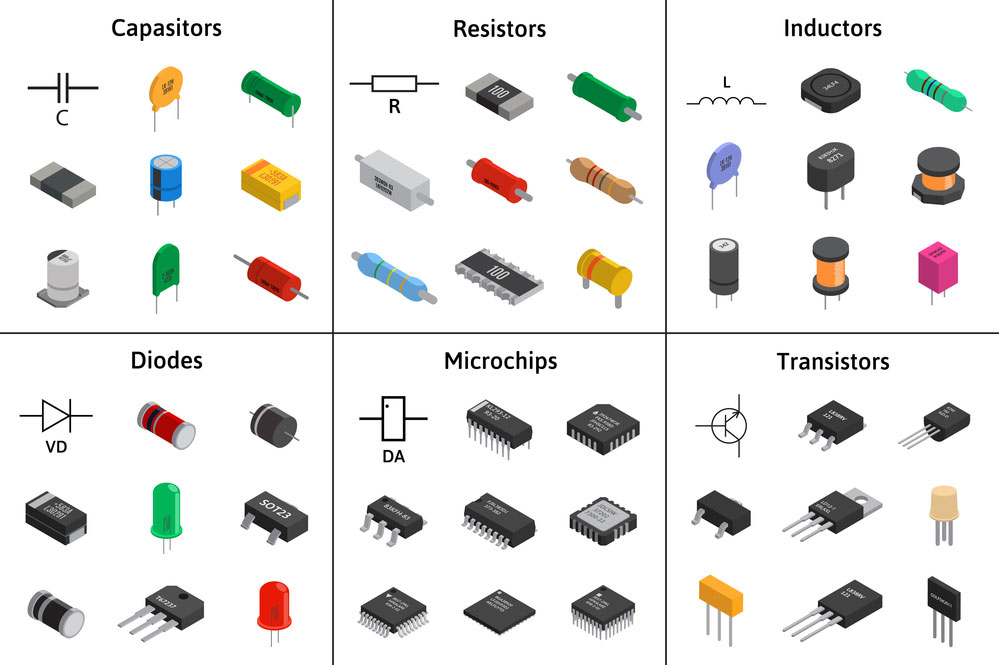
(electronic components.)
How to use LM3914 IC?
To efficiently use the lm3914 IC, you carefully connect the 10LEDs and the IC. After that, modify the reference voltages of the input signal and ensure the current flowing through the LED is under control. Next, you power the display circuit from pins 2 and 3. Then the course transfers the output analog signal voltage to pin 5.
To achieve proper circuit functioning, ensure that the single supply voltage is at least 1.5v more than the 5v monitoring voltage. Since the monitoring voltage has a wide range of 0-5v, pin four is set to 0v. Then, pin six is set on 5v.
Also, pay attention to connecting all the ten bulbs without any current limiting resistor. To clarify, you make this connection because an internal current limiter set from pin 7 exists in the IC.
Additionally, ensure you connect the cathode of the build to the circuit while the anode connects directly to the +5v. We make this connection because the output pins of the course cannot source current; however, it can sink current.
You also know that this lm3914 IC has two modes of operation. In the bar mode, you connect pin 9 to pin 3. The input voltage determines whether the bulb will go on or off when this happens. However, in the dot mode, pin 9 remains open, and this connection results in the bulb turning on. Additionally, the bulb turning on also depends on the input voltage applied.

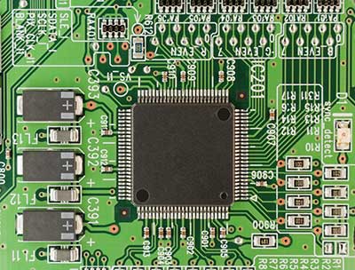
(a circuit board.)
Applications of the lm3914
- First, you can use lm3914 IC in both digital and analog gauges.
- We use this integrated circuit in a lead-acid battery charger monitor and crude battery level indicators.
- Thirdly, it is a crucial circuit in an automatic temperature controller.
- Also, we use it in electronic displays.
- Additionally, it is a critical component in low-cost monitoring devices, and we employ it as a soil moisture tester circuit.
- Lastly, we use the lm3914 as a temperature meter circuit.
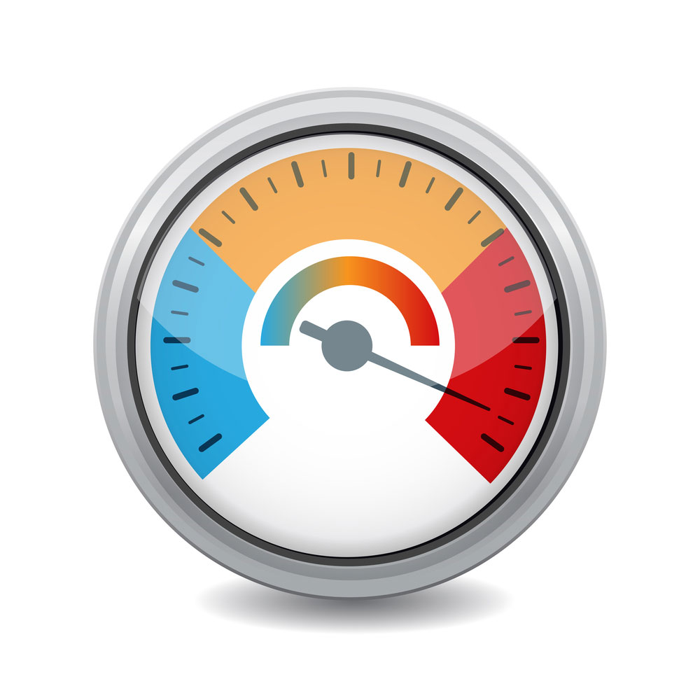
(a temperature(digital) gauge we use in cooking.)
Summary
The lm3914 circuit is a piece of crucial electronic equipment found in the ICs series. We also discussed ways to use the lm3914 IC in your projects and get the most out of them!
We hope this article has been of help to you. Consider sharing this article with friends and family who might be interested in making and learning more about circuit boards. For any queries or services on this or any of our articles, please do not hesitate to contact us.
Special Offer: Get $100 off your order!
Email [email protected] to get started!