Checking for faults and discontinuities by measuring impedance in PCBs is not a walk in the park. Why? Impedance is a property of AC that you cannot measure easily, like resistance. The best way to go about this process is to use TDR measurements. We have analyzed TDR measurements and the best instruments used for this PCB testing process in detail below. Let's get right into it!
Contents
- What are TDR Measurements?
- TDR Measuring Instruments
- Time Domain Reflectometer (TDR)
- Vector Network Analyzer (VNA)
- TDR vs. VNA: Which One Is Better?
- TDR Features
- Velocity Factor (Vf)
- Accuracy
- Output Pulse Level
- Automatic Fault Finding
- Range
- Factors Affecting TDR Resolution
- TDR Impedance Measurement Rise Time
- TDR Impedance Measurement Edge Speed
- TDR Impedance Measurement Ringing Effects/ Aberrations
- Factors Affecting TDR Measurement Accuracy
- Reference Impedance
- Incident Pulse Aberrations
- Baseline and Step Amplitude Corrections
- Noise
- Cable Losses
- Interconnect Accuracy
- How To Interpret TDR Tests
- Wrap Up
What are TDR Measurements?
Time Domain Reflectometry measurements are tests used to identify the location and nature of faults along cables. These tests involve sending a low-voltage electrical pulse into a transmission line, which gets reflected into the TDR by the cable fault.
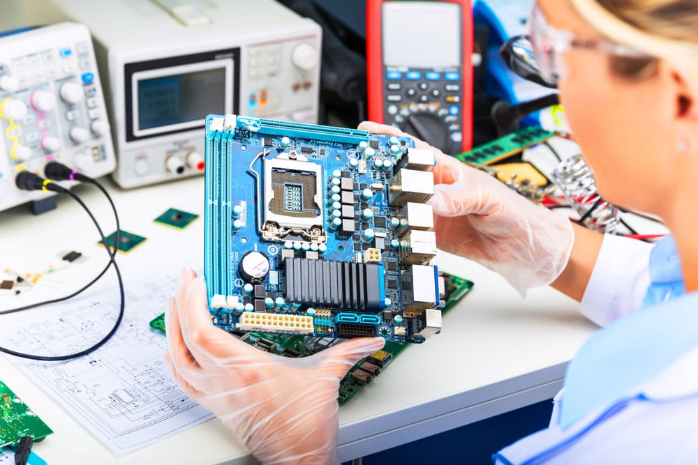
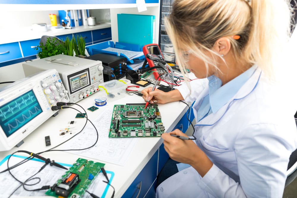
An electronics engineer is examining a computer motherboard. Note the TDR device in the background.
The reflection curves help technicians or engineers identify the issues, which could be either of the following:
- An open cable end
- Splice
- Short circuit
- Intruding water
- Bad contact
- Water in the cable
- Split/Resplit
TDR Measuring Instruments
Electrical engineers generally agree that there are two instruments for measuring TDR.
Time Domain Reflectometer (TDR)
As the name suggests, a Time Domain Reflectometer operates in the time domain. It is an electronic device that consists of a high-speed oscilloscope and a sampling module.
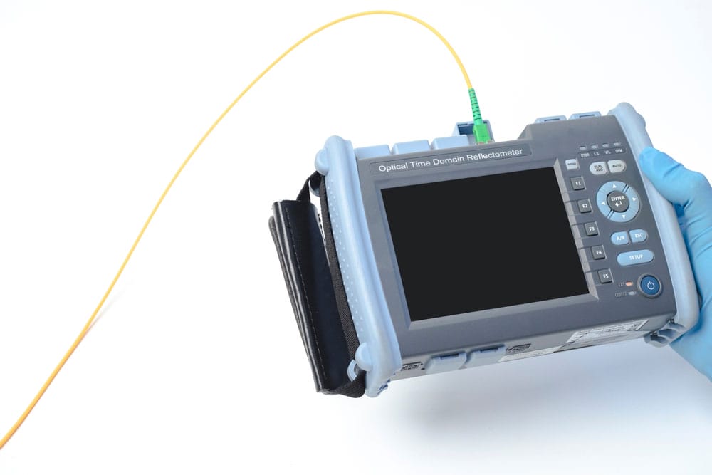
A TDR for checking for discontinuities in fiber optic transmission lines
The sampling module generates a voltage step signal, then propagates it into the transmission medium under investigation. On the other hand, the oscilloscope adds the incident step signal & reflected voltage algebraically. It then monitors these two parameters to determine the nature of the fault. Inductive, resistive, and capacitive faults give different responses. In a nutshell, the device determines line issues using reflected waveforms.
A digital oscilloscope
TDR measurements are not in absolute units, like volts. Instead, the reflectometer bases them on the ratio of reflected voltage to transmitted voltage, which is the reflection coefficient.
Vector Network Analyzer (VNA)
Compared to a TDR, a VNA operates in the frequency domain. The instrument measures the S-parameters of a microwave or RF device, then displays the results in the frequency domain. It runs like a scalar analyzer but with the extra ability to provide accurate measurement of a device's phase over a wide dynamic range.
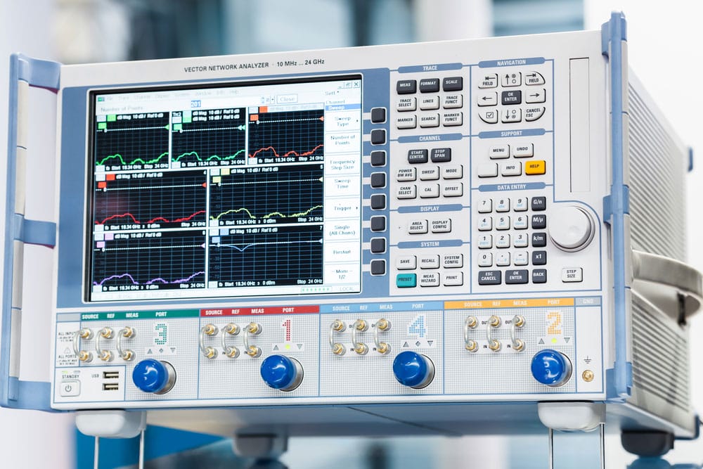
A Vector Network Analyzer in action
The device also features an inverse FFT (Fast Fourier Transform) to convert the frequency domain to a time domain. A VNA can use a low-pass or band-pass time domain processing technique.
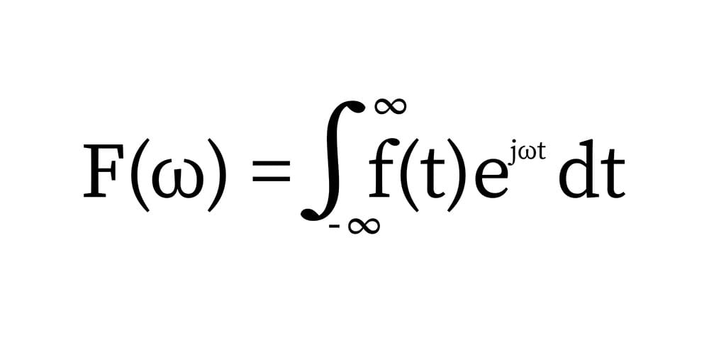
The Fourier Transform mathematical function
TDR vs. VNA: Which One Is Better?
A TDR does temporal analysis, which means it is easy to set up, features intuitive controls, and is a results-oriented instrument. On the other hand, a VNA excels in frequency domain analysis. Its measurements are stable, versatile, and precise.
But the VNA requires calibration and must use an inverse FFT to take time domain measurements. This uncertainty of the VNA's measurement makes it inferior to the TDR.
Special Offer: Get $100 off your order!
Email sales@ourpcb.net to get started!
TDR Features
A TDR contains these vital features.
Velocity Factor (Vf)
The velocity factor is the ratio of the pulse's speed on the trace to the speed of light. It is essential to know the velocity of the signal pulse propagating through the line for TDR operation.
A TDR measures the duration between the release and return of the low voltage pulse from fault location reflections. After that, it converts the time taken by the reflected pulse to distance using the Vf.
Accuracy
A TDR's accuracy depends on the Vf. Therefore, you should test the trace from both ends to "calibrate" it before use.
Output Pulse Level
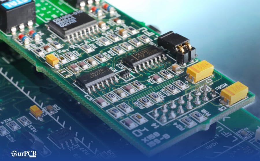
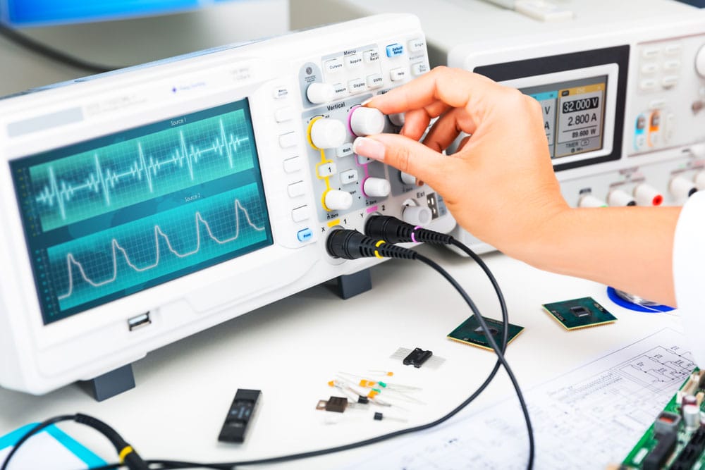
You can vary the pulse level at the output to help locate discontinuities. Small discontinuities and those on the far end of the trace require a high or strong pulse level. However, high pulse levels sent to near faults can distort a large section of the reflected waveform. Therefore, this adjustment is critical for accurate troubleshooting.
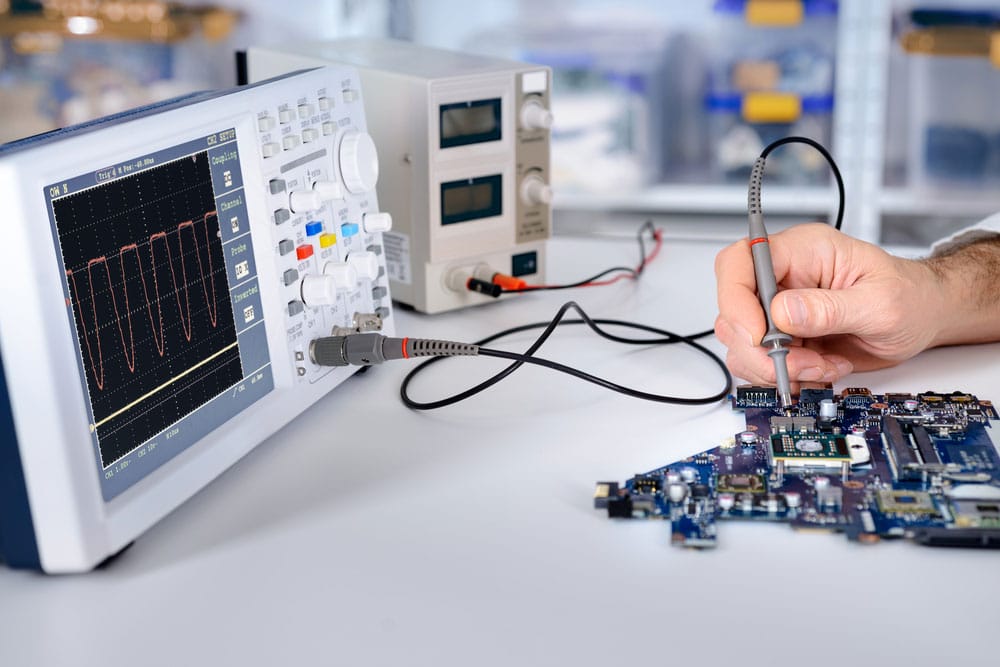
An engineer testing electronic components in a PCB
Automatic Fault Finding
Most TDRs can identify some faults automatically. But it is necessary to use the instrument manually to get the most from it.
Range
The range is adjustable, and it is best to set it above the expected trace length to give a complete picture of the situation. Otherwise, you can miss spotting significant faults because they might not appear on display.
Factors Affecting TDR Resolution
If a TDR does not have the maximum resolution, it can smoothen out tiny and closely-placed discontinuities into one aberration in the waveform. This effect can hide the faults and lead to inaccurate impedance readings & measurements.
TDR Impedance Measurement Rise Time
Reflections caused by discontinuities in the electrical path have rise times slower or equal to the incident signal's rise time. Spacings between two discontinuities in the transmission path can determine how close the positions of their reflections will be on the TDR waveform.
Quick rise times are usually desirable, but they can give confusing results on the TDR. You can rectify misleading impedance readings by compromising on the environment needed by real operational signals.
It is best to see the transmission medium's TDR response to rise-times match the circuit operation. Some reflectometers enable you to increase the incident signal's apparent rise time to match the two.
TDR Impedance Measurement Edge Speed
Impedance gets measured on the flat top of the pulse, not the edge. But edge speed is still relevant because it affects the measurement resolution.
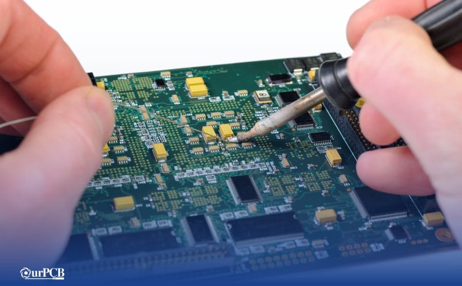
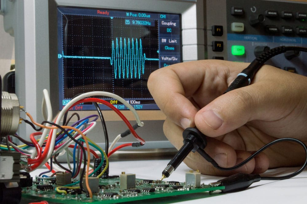
An engineer troubleshooting issues in a PCB’s electronic components
A fast edge reveals a short discontinuity. On the other hand, a slow edge can only highlight long discontinuities. But the response to small discontinuities also means fast edges can react to the signal injection pads, probe tip, vias, and the injection points of board test traces.
An example is when a differential signal pair spreads out to get to the probe pads. The resulting waveform aberrations can distort or mask the measurement waveform's test region.
TDR Impedance Measurement Ringing Effects/ Aberrations
Ringing is an aberration in the incident wave. Aberrations reach discontinuities ahead of the incident wave and begin generating reflections. This effect reduces the TDR resolution, creating closely-spaced discontinuities.
Factors Affecting TDR Measurement Accuracy
Reference Impedance
TDR impedance measurements occur by comparing reflected wave amplitudes to incident signal peaks, then providing the results in rho or ohms. But the measurement process depends on the accuracy of the reference impedance. Some TDR devices use connectors as stable impedance references to calculate reflection coefficients.
Incident Pulse Aberrations
As stated earlier, incident pulse aberrations affect TDR resolution by generating reflections. If these reflections don't settle quickly, they will create errors in the amplitude's accuracy.
A technician fixing a motherboard
Baseline and Step Amplitude Corrections
Modern TDR devices keep track of the incident step amplitude and baseline periodically, then compensates the TDR system automatically. This compensation can cause inaccuracies.
Noise
Modern TDR devices also use signal-averaging techniques to minimize the effects of random noises when measuring tiny impedance variations. Averaging reduces the system's processing speed, which affects measurement accuracy.
Cable Losses
Long cables affect the accuracy of the measured waveform by doing the following.
- Making the DUT impedance appear higher than the actual value
- Degrading the rise and settling time of the incident pulse
It is okay to ignore the amplitude inaccuracies if the DUT impedance is close to 50 ohms. But you must consider these inaccuracies if the impedance is larger or smaller.
Interconnect Accuracy
The probe-to-DUT interface and interconnect components can create inductive reflections that must settle to enable accurate measurement. Therefore, having short ground leads and probe tips is better.
How To Interpret TDR Tests
A TDR requires two parallel conductors to identify impedance changes. Any fault, trace break, connection, etc., will vary the impedance value, creating a different waveform effect on the display.
A signal waveform when assessing a circuit
Positive reflections mean high impedance values, while negative reflections imply low impedance values. Some typical measurement waveforms include the following:
- High positive trace (open conductor)
- Negative trace (short circuit)
- Tiny positive followed by short negative (cable joint or splice)
- Negative trace followed by a long positive (T joint)
- Negative trace followed by a stretched positive (split/resplit)
- Short positive, long flat, then short negative (bridge tap)
- Long irregular pulse (water ingress)
- Short positive/ short negative (wet splice)
Wrap Up
In conclusion, TDR measurements are critical for troubleshooting faults and discontinuities in circuit boards. You can use a Time Domain Reflectometer or Vector Network Analyzer for this job, but the former is better because it operates in the time domain. As shown above, the device has several features and factors that affect its resolution and accuracy. That's it for this article! If you have any questions or comments, contact us for more details.
Special Offer: Get $100 off your order!
Email sales@ourpcb.net to get started!