SPDT relays have one input and two output terminals. They can switch between two circuits, allowing current to flow through either one of the two output paths. This makes them ideal for applications where switching between two states is required. SPDT relays can be used in scenarios requiring simple switching, like changing the direction of a motor or toggling between two different power sources.
Contents
- Key Components of an SPDT Relay
- How does an SPDT Relay Work?
- Types of SPDT Relays
- Electromechanical SPDT Relays
- Solid State SPDT Relays
- How do SPDT Relays Compare to Other Relay Types?
- SPDT vs. SPST Relays
- SPDT vs. DPDT Relays
- Technical Specifications of SPDT Relays
- SPDT Relays in PCB Manufacturing
- Signal Switching
- Power Switching
- Isolation
- Control Systems
- Factors to Consider When Choosing an SPDT Relay
- Voltage and Current Requirements
- Temperature Considerations
- Humidity in the Area
- Switching Speed
- Contact Material
- Size and Form Factor
- Design Considerations for Integrating SPDT Relays in PCBs
- Efficient PCB Layout
- Manage Thermal Issues
- Minimise Electrical Noise
- Test Relay Functionality in PCB Prototypes
- SPDT Tutorial: How to Connect and Wire an SPDT Relay
- Stage 1: Use the Correct Connection Diagram
- Stage 2: Connect the SPDT Relay
- Stage 3: Wire the SPDT Relay in a Circuit
- Common Issues and Troubleshooting Methods for SPDT Relays
- Relay Contact Failure
- Incorrect Wiring
- Relay Not Switching
- Coil Failure
- Switching Reliability Issues
Key Components of an SPDT Relay
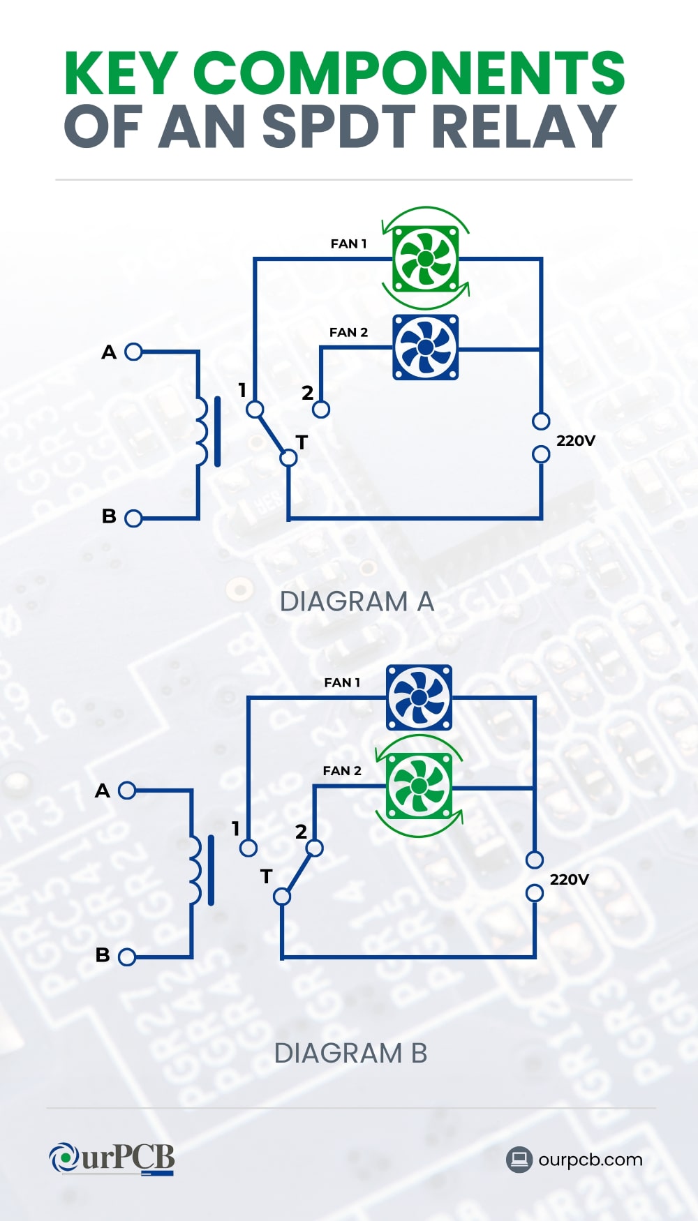
A single pole double throw (SPDT) relay is an essential component in many electrical systems. An SPDT relay, or SPDT relay switch, has several key parts that work together to control and switch electrical circuits while contributing to reliable SPDT relay output capabilities. Here are the primary components of an SPDT relay:
- Coil: The heart of the relay
- Armature: A movable iron part attracted to the coil when the relay is energized
- Contacts: Common (COM) contact, a normally closed (NC) contact, and a normally open (NO) contact
- Spring: Returns the armature to its original position when the coil is de-energized
- Frame: Provides structural support for the relay components
- Insulating Material: Isolate different parts of the relay from each other to prevent short circuits
How does an SPDT Relay Work?
When the coil of an SPDT relay is energized, it creates a magnetic field that pulls the armature. This movement changes the connection of the contacts, switching the circuit from the NC position to the NO position.
When the coil is de-energized, the spring returns the armature to its default position, reconnecting the COM contact to the NC contact. This simple mechanism allows SPDT relays to effectively control electrical circuits by switching between two different paths. Moreover, this SPDT relay function is ideal for managing SPDT signals in various applications.
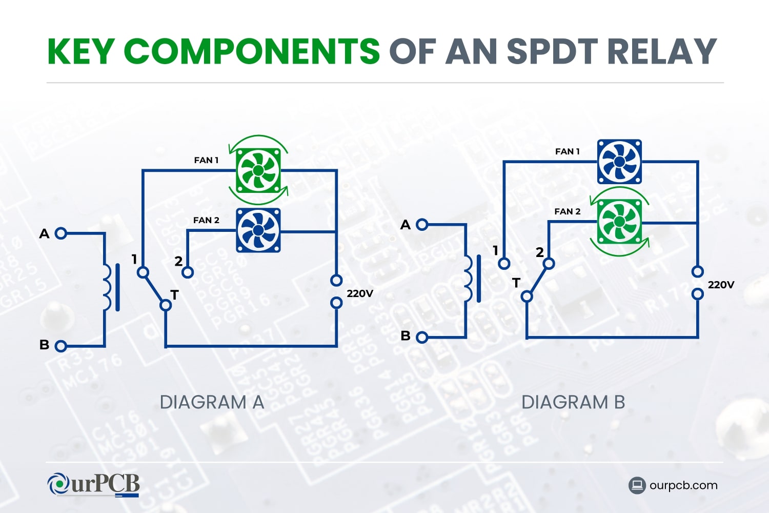
It’s always a good idea to visualize key components and functioning as an SPDT relay diagram and schematic, which helps to clarify the relay's operation as an electromagnetic switch that redirects current between two outputs.
Types of SPDT Relays
SPDT relays are a type of switch that can connect a common terminal to one of two other terminals. There are two main types of SPDT relays: electromechanical and solid state.
Electromechanical SPDT Relays
Electromechanical SPDT relays are the traditional type of relays that use a physically moving part to make or break a connection. They are commonly used in automotive systems (like power windows and headlights), industrial machinery, and home appliances. When integrating SPDT relays into vehicle electrical systems, partnering with experienced automotive wire harness manufacturers ensures proper relay integration and reliable electrical connections throughout the vehicle.
Solid State SPDT Relays
Solid state SPDT relays, on the other hand, do not have any moving parts. Instead, they use semiconductor devices such as thyristors or transistors to switch the circuit electronically. They are widely used in applications like HVAC systems, lighting controls, and electronic devices, where silent and rapid switching is important for effective functioning.
How do SPDT Relays Compare to Other Relay Types?
SPDT vs. SPST Relays
Single pole double throw relays and single pole single throw (SPST) relays are both commonly used in various applications, but they serve different purposes.
| Type | Functionality | Applications | Advantages |
| SPDT | One input, two outputs; switches between two circuits | Simple tasks like motor direction or power source switching | Versatile for multiple outputs, simpler than DPDT |
| SPST | One input, one output; simple on-off switch | Basic on-off control like lighting systems | Simple, reliable, and easy to implement |
| DPDT | Two inputs, four outputs; controls two circuits simultaneously | Complex tasks like reversing motor polarity | More control, reduces need for multiple relays |
SPDT Relays
- Functionality: SPDT relays are equipped with two output terminals and one input terminal. With their ability to switch between two circuits, current can pass through one of the two output routes. Because of this, they are perfect for uses requiring the transition between two states.
- Applications: Employed in situations that need for basic switching, such as reversing a motor's direction or moving between two power sources.
- Advantages: Versatility in switching between two circuits. They’re suitable for more complex control systems where multiple outputs are needed.
SPST Relays
- Functionality: SPST relays have one input and one output. They function like a simple on-off switch, controlling a single circuit. When the relay is energized, the circuit is completed, allowing current to flow.
- Applications: Commonly used in straightforward on-off control applications like lighting systems, where a single circuit needs to be opened or closed.
- Advantages: Simplicity and reliability. They’re easier to implement in basic applications requiring simple on-off control without the need for multiple outputs.
SPDT vs. DPDT Relays
Double pole double throw (DPDT) relays offer even more functionality compared to SPDT relays, making them suitable for more complex applications.
SPDT Relays
- Functionality: SPDT relays have one input and two outputs. They can switch between two circuits, providing flexibility in simple switching applications.
- Applications: Used for straightforward switching tasks, like toggling between two power sources or changing the direction of a device’s operation.
- Advantages: Versatility for applications needing two output paths. Simpler wiring and control logic compared to DPDT relays.
DPDT Relays
- Functionality: DPDT relays have two inputs and four outputs. Each input can connect to one of two outputs, allowing two separate circuits to be controlled simultaneously. This means a DPDT relay can perform the functions of two SPDT relays.
- Applications: Ideal for more complex switching needs, like reversing the polarity of a motor or controlling two different devices at the same time.
- Advantages: Greater control and flexibility. They allow for more intricate control systems, reducing the need for multiple relays in more complex applications.
Special Offer: Get $100 off your order!
Email [email protected] to get started!
Technical Specifications of SPDT Relays
SPDT relays have one input and two outputs, where one input can switch between two outputs. Key technical specifications include:
| Specification | Description |
| Contact Configuration | SPDT relays have one common terminal, one normally open terminal, and one normally closed terminal. |
| Coil Voltage | Voltage required to energize the relay coil, typically 5–48 V DC or AC, depending on relay type. |
| Contact Material | Common materials include silver alloy, gold, and other precious metals for low resistance and longevity. |
| Insulation Resistance | High insulation resistance (usually in megohms) ensures safe operation without leakage currents between contacts. |
| Operating Time | Time taken for the relay to switch from one state to another, usually 5 to 15 milliseconds. |
| Release Time | Time required for the relay to return to its default state after de-energizing, typically 2 to 10 milliseconds. |
| Dielectric Strength | Ability to withstand high voltage between the coil and contacts or between open contacts, often specified in kilovolts. |
| Typical Voltage Ratings | Maximum voltage the relay contacts can handle, with common ratings of 5 V, 12 V, 24 V, 48 V, 120 V, and 240 V. |
| Current Ratings | Maximum current the relay contacts can carry without overheating or damage, with typical ratings of 1 A, 3 A, 5 A, 10 A, 15 A, 20 A, and 30 A. |
| Physical Dimensions | Size ranges from miniature relays (15 mm x 10 mm x 10 mm) to standard relays (20 mm x 15 mm x 15 mm to 30 mm x 20 mm x 20 mm) and power relays (40 mm x 30 mm x 30 mm or larger). |
SPDT Relays in PCB Manufacturing
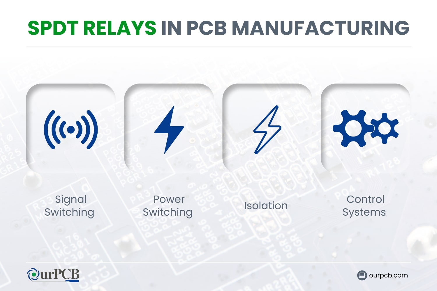
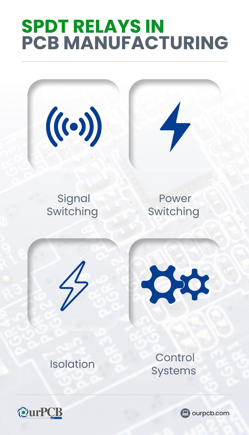
Signal Switching
SPDT relays route signals between different circuit paths. This is necessary where multiple signal paths are required, as in audio equipment, communication devices, and testing equipment. Using SPDT relays allows designers to create more flexible and adaptable circuits. Notably, effective SPDT signal routing can enhance the relay's versatility in electronics applications, particularly in PCB module configurations.
Power Switching
SPDT relays control high-power loads with low-power signals. The ability to handle different voltage and current levels makes SPDT relays ideal for power distribution and management in various electronic devices.
Isolation
SPDT relays provide electrical isolation between different parts of a circuit. This protects sensitive components from high voltages, prevents interference, and helps maintain signal integrity, especially in high-frequency applications.
Control Systems
In control systems, SPDT relays are used to manage and automate processes. They can control actuators, sensors, and other components, which enables precise and reliable operation of complex systems in industrial automation, home automation, and automotive systems.
Factors to Consider When Choosing an SPDT Relay
Choosing the right relay can make or break the efficiency and reliability of your electronic or electrical projects. Several factors must be considered, including:
Voltage and Current Requirements
Understand the requirements of your application first. Relays are designed to handle specific voltage ranges and current levels. Make sure the relay you choose can safely manage the maximum voltage and current of your circuit.
Temperature Considerations
Consider the operating temperature range of the relay and make sure it matches the environment where it will be used. High temperatures can affect the coil resistance and contact integrity, potentially leading to relay malfunction.
Humidity in the Area
Choose a relay with good sealing or a coating to protect against corrosion and electrical shorts caused by humidity. Some relays are specifically designed for harsh environments and can offer better performance under these conditions.
Switching Speed
This is the time it takes for the relay to switch from one position to another. Make sure the switching speed meets the needs of your project. Faster switching speeds are important in high-speed circuits and precise control systems.
Contact Material
Common contact materials include silver, gold, and various alloys. Silver is highly conductive but can tarnish, while gold offers excellent conductivity and corrosion resistance but is more expensive. Choose a contact material that balances performance, cost, and environmental conditions.
Size and Form Factor
The physical size and form factor of the relay should fit the space available in your project. Make sure the relay you select can be easily integrated into your existing design without any significant modifications.
Design Considerations for Integrating SPDT Relays in PCBs
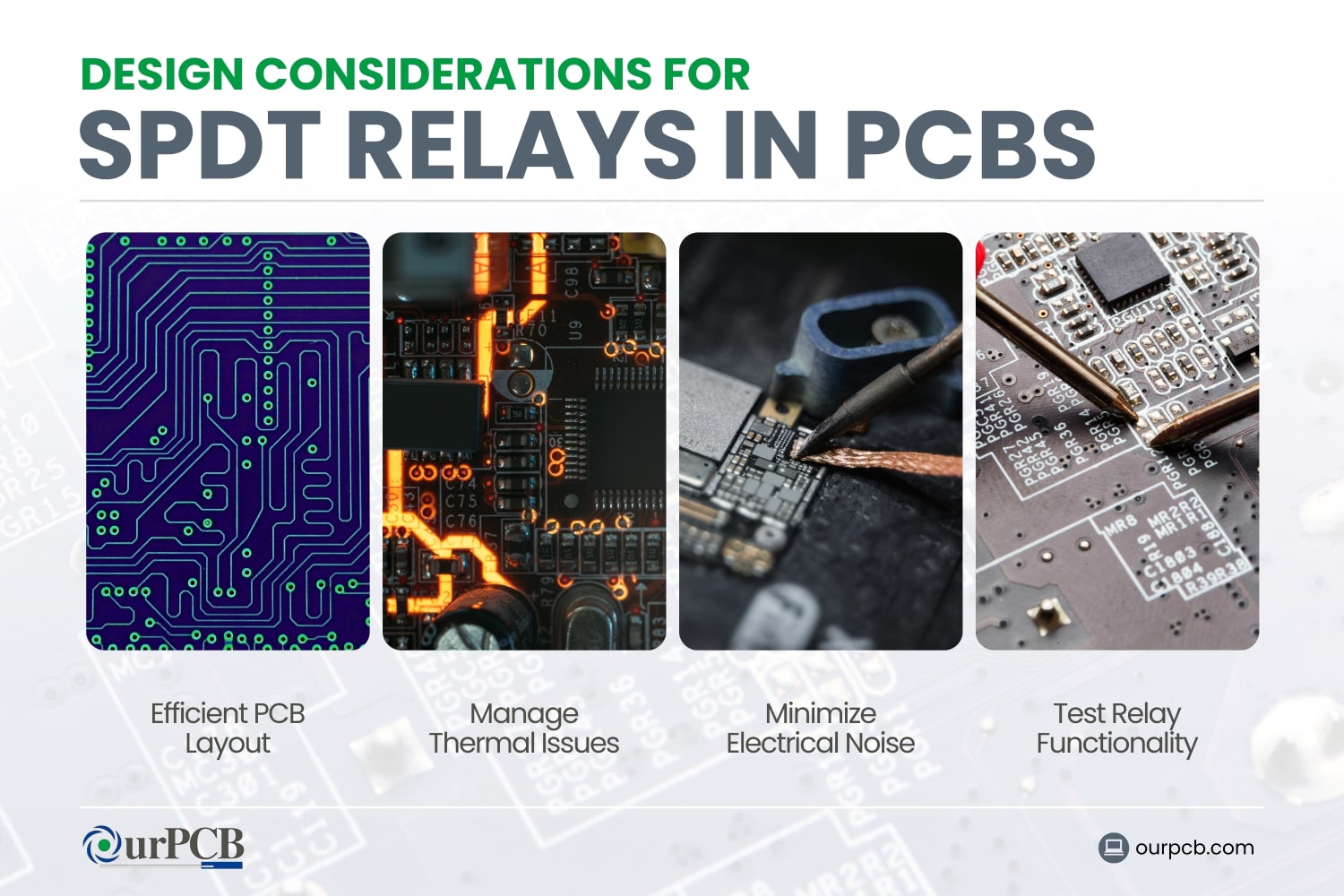
At OurPCB, we take designing efficient PCBs very seriously. Here’s what we recommend considering if you’re designing your own circuit boards with SPDT relays.
Efficient PCB Layout
An efficient PCB layout is non-negotiable for the performance and reliability of circuits using SPDT relays. Here are some tips to achieve this:
- Signal Traces: Keep signal traces short and direct to reduce resistance and potential signal degradation. Do not route traces near noisy power lines or high-frequency signals.
- Ground Planes: Use continuous ground planes to reduce electrical noise and provide a stable reference point for your circuit. Make sure the relay has a good ground connection to minimize interference.
- Component Placement: Group related components together to shorten trace lengths and simplify the routing process. Place the relay near the components it interacts with the most.
- Thermal Management: Design the PCB layout to distribute heat evenly and prevent hot spots. Consider using thermal vias and copper pours to enhance heat dissipation.
- Clearances and Creepage: Have sufficient clearances between high-voltage and low-voltage traces to prevent arcing and ensure safety. Follow industry standards for creepage distances.
Manage Thermal Issues
Excessive heat can lead to component failure and reduced reliability. Here’s how to manage thermal issues effectively:
- Heat Sinks: If the relay or other components generate a lot of heat, consider adding heat sinks to improve heat dissipation.
- Thermal Analysis: Perform thermal simulations during the design phase to identify potential thermal issues and address them before prototyping.
Minimise Electrical Noise
Electrical noise can interfere with the proper functioning of SPDT relays and the overall circuit. Here are some strategies to minimise electrical noise:
- Shielding: Use shielding techniques, like grounded metal enclosures or PCB shielding layers, to protect sensitive signals from external noise sources.
- Decoupling Capacitors: Place decoupling capacitors near the relay coil and other critical components to filter out noise and provide stable power.
- Grounding: Implement a solid grounding strategy with a low-impedance path to ground. This helps reduce noise and prevents ground loops.
- Trace Routing: Route high-frequency or high-current traces away from sensitive signal traces to reduce coupling noise. Use differential pairs for high-speed signals to cancel out noise.
- Filtering: Add filters, such as ferrite beads and LC filters, to suppress noise on power and signal lines.
Test Relay Functionality in PCB Prototypes
Testing the functionality of SPDT relays in PCB prototypes will help you make sure they are reliable. Here’s a step-by-step approach:
- Visual Inspection: Start with a visual inspection of the PCB to check for any obvious issues like solder bridges, missing components, or misalignment.
- Continuity Testing: Use a multimeter to check the continuity of the relay contacts and make sure they switch between the NO and NC positions correctly.
- Power Testing: Apply power to the relay coil and double-check that it activates as expected. Measure the coil voltage and current to make sure they are within the necessary specifications. Note, for circuits involving a diode or requiring a 12v input, ensure that your relay can handle these specifications.
- Functional Testing: Integrate the relay into the circuit and perform functional tests to confirm that it switches correctly under various operating conditions.
- Environmental Testing: Test the relay under different environmental conditions, such as temperature and humidity variations, to make sure it performs reliably.
SPDT Tutorial: How to Connect and Wire an SPDT Relay
Stage 1: Use the Correct Connection Diagram
Before starting, you’ll need to have the correct connection diagram for your SPDT relay. A typical SPDT relay has five pins:
- COM: The pin that moves between the NO and NC contacts.
- NC: The pin connected to the COM pin when the relay is not energized.
- NO: The pin connected to the COM pin when the relay is energized.
- Coil+: The pin where positive voltage is applied to energize the relay.
- Coil-: The pin where negative voltage is applied to complete the coil circuit.
Refer to the SPDT relay diagram and schematic or datasheet printed on the relay case to identify these pins accurately. This is particularly important if your setup includes a 12v power source or protective diode.
Stage 2: Connect the SPDT Relay
- Identify the Pins: Using the connection diagram, identify the COM, NC, NO, Coil+, and Coil-pins on your relay.
- Connect the Coil Pins: Connect the Coil+ pin to a positive voltage source (usually 12 V or 5 V, depending on the relay specifications), and the Coil-pin to ground.
- Connect the COM Pin: Connect the COM pin to the power source or the signal you want to control.
- Connect the NO and NC Pins: Depending on your application, connect either the NO or NC pin to the load. The NO pin is used if you want to power the load when the relay is activated, while the NC pin is used if you want to power the load when the relay is not activated.
Stage 3: Wire the SPDT Relay in a Circuit
To wire an SPDT relay in a circuit, follow these steps:
- Power the Relay: Ensure the relay coil is powered correctly. Connect the Coil+ to the control signal or power source, and Coil- to ground.
- Control the Load: Connect the COM pin to the input power source. This could be the positive terminal of a battery or a power supply.
- Connect the Output: Connect the load (e.g., a light, motor, or another device) to either the NO or NC pin. Your choice will depend on whether you want it to be active when the relay is energized or de-energized.
- Complete the Circuit: Make sure all connections are secure. If necessary, use a multimeter to check continuity and correct any wiring errors.
Common Issues and Troubleshooting Methods for SPDT Relays
Relay Contact Failure
Relay contact failure can happen when the contacts within this electromagnetic switch become worn, pitted, or contaminated, leading to poor SPDT relay output. This can be caused by wear and tear, contamination, or arcing, and may result in unreliable or no electrical connection.
Troubleshooting
- Inspect and Clean Contacts: Check for dirt or debris and clean with a contact cleaner.
- Replace Contacts: If worn or pitted, replace the contacts or the entire relay.
- Reduce Load: Make sure the relay operates within its specified load limits to prevent arcing.
Incorrect Wiring
Incorrect wiring can prevent a relay from functioning properly. This issue often arises during installation or maintenance, due to incorrect connections, loose connections, or wrong polarity.
Troubleshooting
- Check Wiring Diagrams: Compare the relay’s wiring to the provided diagram.
- Secure Connections: Make sure all wires are properly fastened.
- Verify Polarity: Double-check the power supply connections.
Relay Not Switching
A relay that doesn’t switch can prevent circuits from operating correctly. It could be caused by a damaged coil, a mechanical obstruction, or not getting enough voltage.
Troubleshooting
- Measure Voltage: Use a multimeter to make sure the coil receives the correct voltage.
- Inspect Coil: Check for visible signs of damage or burning.
- Check Mechanism: Make sure no debris or obstruction is inside the relay.
Coil Failure
Coil failure prevents the relay from activating, leading to circuit failure. It can happen due to overheating, overvoltage, or physical damage to the coil.
Troubleshooting
- Measure Resistance: Check the coil’s resistance with a multimeter; an open circuit indicates a broken coil.
- Inspect for Damage: Look for signs of overheating or physical damage.
- Replace Coil: If damaged, replace the coil or the entire relay.
Switching Reliability Issues
Switching reliability issues can lead to intermittent or unreliable circuit operation. It may be caused by an inconsistent power supply or vibrations that cause “contact bounce”, rapid uncontrolled switching.
Troubleshooting
- Stabilize Power Supply: Use a regulated power supply for consistent voltage.
- Secure Relay: Mount the relay securely to minimize vibrations.
Use Debouncing Circuits: Implement circuits to reduce contact bounce.
Back to Top: Single Pole Double Throw (SPDT) Relays
Special Offer: Get $100 off your order!
Email [email protected] to get started!