When you hear about the alarm clock circuit, the first thing that may come to mind is the alarm clock. No doubt, you're correct, but the device also works for other applications we'll discuss later in the article.
The circuit helps you shun your alarm clock for the weekend after a long week. And this is no surprise because the circuit has a real-time display, sleep timer, snooze functions, etc. Plus, it can turn your electrical appliance power supply off/on—at a set time.
In summary, it's a fun project to jump on if you're looking for a simple alternative that relates to time.
Let's get to work!
Contents
What is an Alarm Clock Circuit?
It's a simpleelectric circuit that notifies you of an intruder, system malfunction, detected condition, and other fundamental concepts regarding intrusions.
So, you can use the devices in different applications like:
- A timer for home electrical appliances
- Display of elapsed time
- Clock radio
- Alarm clock
- Digital clocks with LCD
Special Offer: Get $100 off your order!
Email [email protected] to get started!
What Components Do You Need for Your Alarm Clock Circuit?
Before we give you a glimpse of the alarm clock circuit diagram, here are the components that will get you started:
- C1 (470µF)
- R5 (10K)
- C2, C3 (10nF)
- D1, D2, D3 (IN4001)
- IC1 (LM 8560)
- C4 (10µF)
- R4 (91K)
- IC2 (LM 386)
- R3, R2 (120K)
- C5, C6 (100nF)
- Duplex LED display
- R1 (100K)
- C7 (100µF)
- T1 (0 to 12V / 500mA transformer)
- Switches (S1, S2, S3, S4)
- P1 (10K potentiometer)
- B1 (Buzzer)
Diagram and Design of The Alarm Clock Circuit
With the diagram in mind, let's take a look at the design.
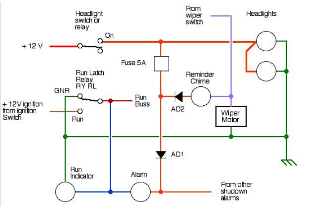
Circuit Diagram of the alarm clock
Source: Wikimedia Commons
IC1 (LM 8560)
The IC1 is one of the basic concepts of the circuit as its drivers help activate the duplex LED digital display signal that displays the time. So, the LM 8560 supports 12 and 24 HR time formats, and it shows snooze function, current time, and alarm support.
Duplex LED Display
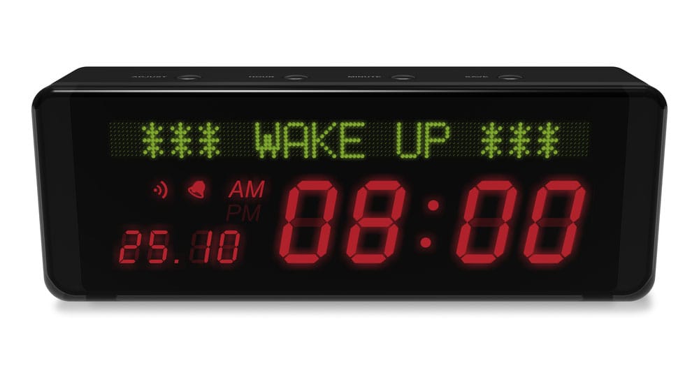
Digital LED display
This component comes in handy for showing different information like alarm notification, current time, etc. So, the LED display saves you the stress of using extra drivers with electronic systems to initiate the display unit. And it's because all the drivers you need are in the alarm clock IC.
IC2 (LM386)
The IC2 helps drive the alarm buzzer. Plus, the audio power amplifier (low voltage) gets power via apotentiometer that receives a signal from the LM 8560's alarm output.
S1-S4 (Push Button Switches)
With the (S1, S2, S3, and S4), you can do three essential things: turn off the alarm, set time, and set the alarm. Further, you can also use these components to set your alarm time in hours and minutes separately.
B1 (Buzzer)
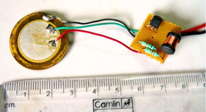
Alarm clock buzzer
Source: Wikimedia Commons
An audio power amplifier is responsible for initiating the buzzer. And it helps to signal an alarm at a set time.
Diodes (D1, D2, and D3)

Three diodes
Each of the diodes has a specific function. For instance, the D1 combines with the C1 (capacitor) to generate a direct current.
When this happens, the voltage goes to the LM 8560 (IC1). Also, the other diodes (D2 & D3) behave like a switch signal generator to the duplex display's cathode. Plus, they also contribute to the LM 8560's input.
T1 (Transformer)
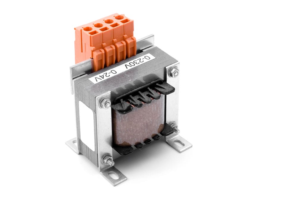
Transformer
Thetransformer is functional when stepping down a high AC supply (220-240V) to about 12V alternating current.
How Does the Alarm Clock Circuit Work?
First off, this alarm clock circuit is more like a simple one. When the mains' input moves to the transformer, the component helps to change the input voltage to a 12V AC signal.
When this happens, the diode (D1) and capacitor (C1) swing into action by changing the AC voltage to DC. Then, it supplies the IC1's Vdd (Pin 20). Since the IC1 works at a particular frequency (50/60 Hz), it can signal the mains. And it does this by using the resistor R1 to the IC1's Pin 25.
Further, the diodes (D2 and D3) give conforming inputs to the display's cathode. So, it's necessary to set a time when you switch on the power source. At this point, you should see the current time. And you can set it by using S1 & S2.
How Do You Set Time?
The first switch (S1) helps you set the hours, while S2 helps you develop minutes. With this, the IC will activate the display linked to it automatically. Also, you'll see the time on the duplex LED display.
You'll also notice that a colon separates the hour and minutes bits. And it's because the duplex LED display is a 4-bit seven-segment. Hence, two bits each will display for an hour and minutes.
What if you want to differentiate the alarm time from the current time?
To do that, you can use the S3 switch because it helps to initiate the LM 8560's alarm display internally. In addition, you can set the alarm time by holding S3. Then, you can select the hour with S1 and the minutes with S2.
Once you finish that, the IC will be on standby for the alarm time. So, when the alarm time is due, Pin 3 will produce an alarm output signal. With this, you can make a direct connection with a small buzzer for the alarm output.
The potentiometer P1 helps you control the alarm signal's pressure and volume from the buzzer. And the potentiometer allows you to receive the alarm output signal from IC1 and IC2's Pin 3. To cancel the alarm before it triggers, you can use the S4 switch, and plus, you can use the S4 button also to stop the alarm any time before it activates.
In addition, if you want the repeat and snooze facilities, use the extra IC1 in the circuit to enable the function.
Steps to Creating a Digital Alarm Clock With the Alarm Clock Circuit
Electronic Circuit of Digital alarm clock
- Reference the circuit diagram above. Then, upload the Arduino code. Afterward, your LCD will show the current date and time.
- Press the switch button to set the alarm. Consequently, it will enter the alarm mode and request two things: the hours and current time. When this happens, press the S1 switch to change the hours.
- When you set your alarm, press the S2 switch to get the minute's tab.
- All the information you entered in your alarm is stored in the Arduino's EEPROM. And your device will always compare the values with the present time. So, the buzzer of your notice will activate when the current value and stored values match. To stop the alarm, press the S4 switch.
Important Points to Note
- If you don't want your supply from the mains, switch things up by designing a battery-powered device. For this, you'll need to produce a 50Hz Sine wave with an oscillator. That way, the IC1 will work perfectly.
- You can explore other ICs, asides from the ones mentioned here, like MM 5387, LM 8361, and TMS 3450.
- Add two more switches to the LM 8560—if you want to use the repeat alarm function.
Wrapping Up
The alarm clock circuit is a valuable device when you're dealing with electrical appliances that require timing. And it helps you to control your alarm clock effectively.
Interestingly, it isn't a tasking project, and all you need to do is get your materials and start building. Do you plan on doing this project? Feel free to reach us—we'll be more than excited to help.
Special Offer: Get $100 off your order!
Email [email protected] to get started!