At OurPCB, we provide comprehensive solutions for integrating relays into your PCB designs. Whether you need electromagnetic, solid-state, or hybrid relays, our team ensures reliable and efficient relay circuits for diverse applications. Explore our PCB relay options to enhance your electronics projects with precision and performance.
Contents
- What is a PCB Relay?
- How PCB Relays Work?
- Protection and Control Functions of PCB Relays
- Types of PCB Relays Based on Operation Principle
- Electromagnetic Relays
- Solid State Relays
- Hybrid Relays
- Thermal Relays
- Types of PCB Relays Based on Throws and Poles
- SPST
- SPDT
- DPST
- DPDT
- How Does a PCB Mount Relay Operate?
- Relay Pin Terminals
- Common Applications of PCB Relays
- PCB Relay Design Considerations
- PCB Design Requirements for Electromagnetic Relays
- Types of Relay PCBs
- How to Solder a Relay on a Circuit Board
- How to Test a Circuit Board Relay
What is a PCB Relay?
A PCB relay, or Printed Circuit Board relay, is the small electronic device designed for controlling electrical current flow within a circuit. PCB relay is integrated directly onto a printed circuit board, enabling efficient control of low-power signals over high-voltage circuits. PCB relays provide galvanic isolation, a crucial feature that prevents high-voltage spikes from affecting the low-power components.
How PCB Relays Work?
PCB relays use an electromagnetic coil to move an armature that opens or closes electrical contacts, controlling large currents with small signals. When activated, the coil's magnetic field shifts the armature, altering the circuit's state. A spring resets the armature when deactivated, making PCB relays crucial for managing power in electronic devices efficiently.
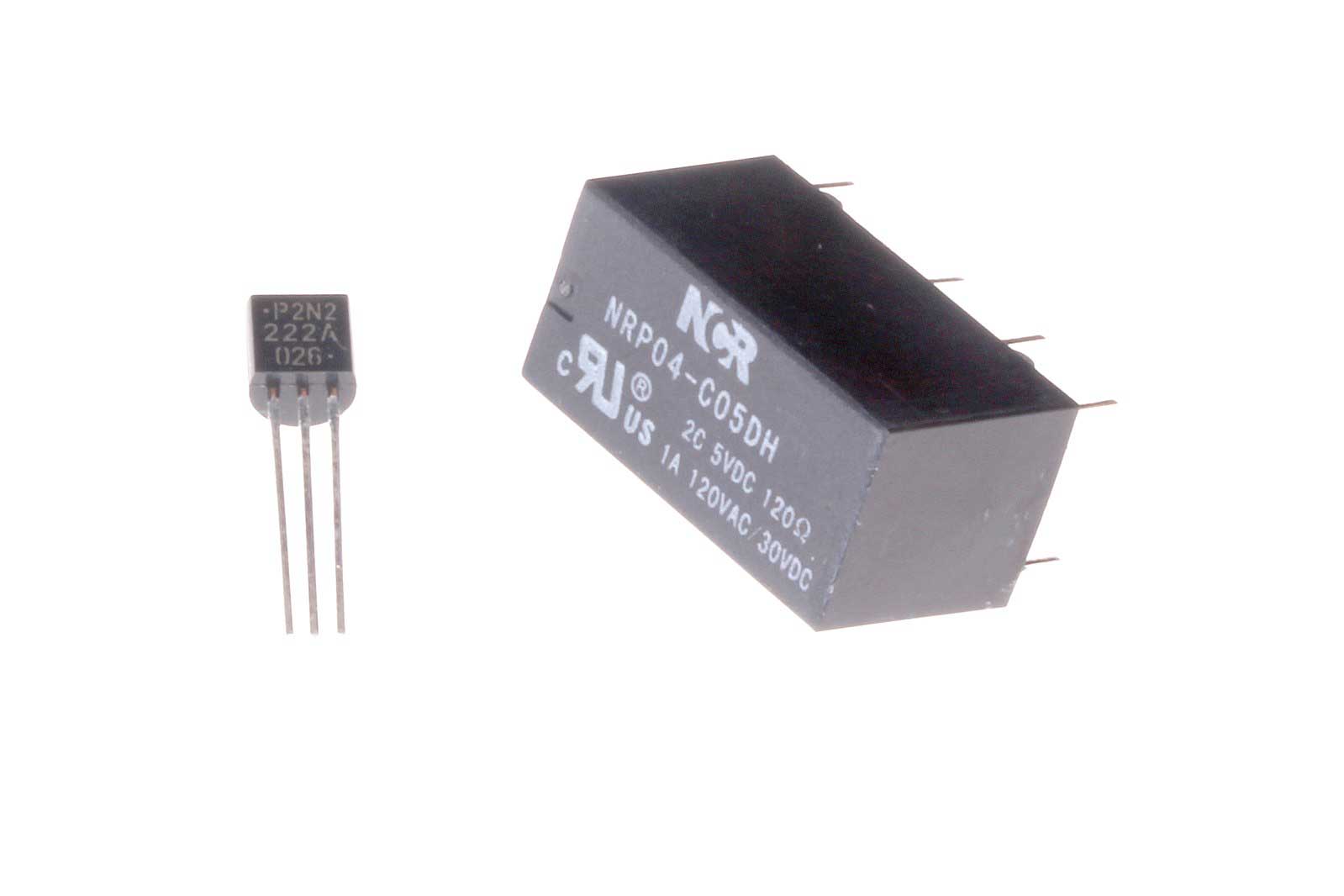
A PCB relay is placed next to a transistor. Compare the sizes.
Source: Wikimedia Commons
Protection and Control Functions of PCB Relays
Even though they are smaller and have lower voltage ratings, these miniature relays operate like the standard ones.
They have the following functions that usually depend on their type.
- High Voltage Switching: As electromechanical devices, these relays are crucial for applications involving high-frequency and high-voltage signals. They are designed to handle significant currents and voltages, making them suitable for robust switching needs.
- Overcurrent Protection: PCB relays provide essential safety by preventing excessive current from flowing inappropriately within a circuit, thus safeguarding other components from damage.
- Thermal Protection: These relays are equipped with mechanisms to trip if the system's temperature surpasses a predetermined threshold, offering critical protection against thermal overloads.
- Differential Protection: Activating when discrepancies arise between currents or voltages in different parts of a circuit, differential relays are vital for maintaining circuit integrity and preventing electrical faults.
- Frequency Protection: To ensure the stability of AC power systems, these relays trip either when the frequency drops too low or spikes too high, which could otherwise lead to system malfunctions.
- Time Delay: Offering controlled operational delays, these relays trigger only for a specified duration, allowing for precise control over circuit functions.
- Semiconductor Relays: Unlike their mechanical counterparts, semiconductor relays switch electronically, providing faster, more reliable switching with reduced mechanical wear.
Types of PCB Relays Based on Operation Principle
PCB relay categorization depends on structure, positioning, application, and contacts. Using these factors, we have the following classification of relays.
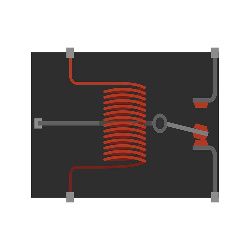
Electromagnetic Relays
Electromagnetic relays contain electrical and mechanical components that move mechanical contact sets when activated.
The primary part of this system is the electromagnet, which creates a magnetic field to open or shut the contact sets.
You can use AC or DC in this relay, and the most common kinds are the induction and attraction types. 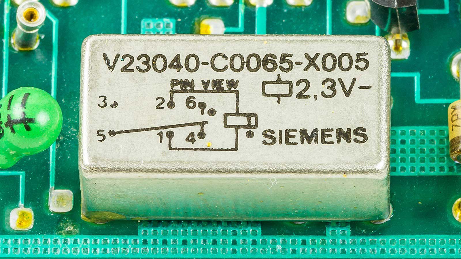
An electromagnetic relay
Source: Wikimedia Commons
Solid State Relays
Switching in a solid-state relay uses semiconductor elements, not mechanical components.
Also, this device has a higher power gain than the electromagnetic PCB relay.
This high gain is due to their lower energy control relative to their high power output. 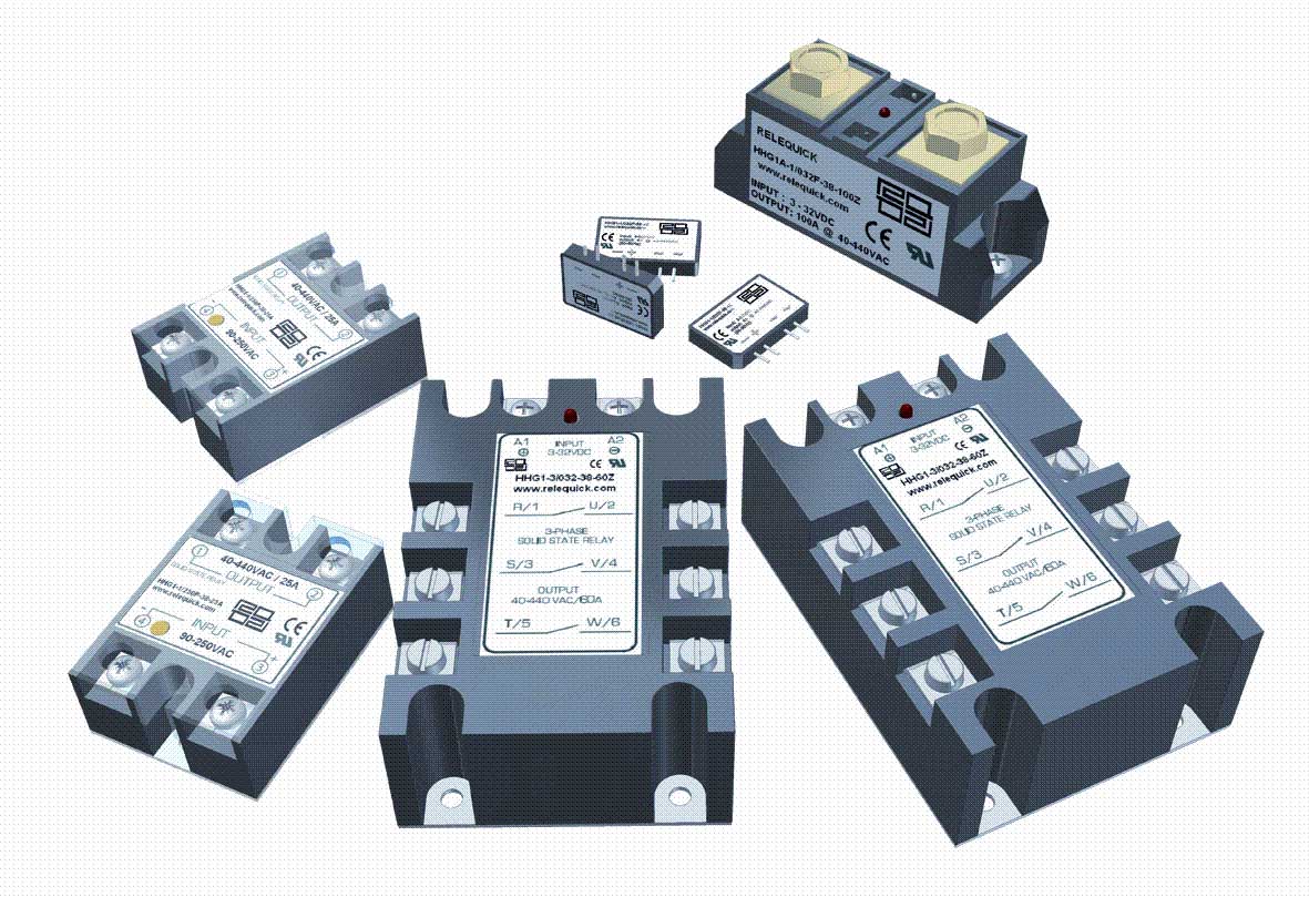
Solid-state relays
Source: Wikimedia Commons
A solid-state relay delivers faster switching capabilities than a conventional PCB power relay.
Additionally, it operates quietly and has a long lifespan due to the absence of contacts.
Some examples include photo-coupled and transformer-coupled relays.
Hybrid Relays
These relays include electromagnetic and electronic components operating together but in parallel positioning.
The electrical part of the relay handles rectification, while the electromagnetic component takes care of the output section.
The primary benefit of this setup is lower energy loss compared to solid-state relays, resulting in reduced power consumption.
Thermal Relays
Thermal relays switch by reacting to temperature changes and shifting contact positions.
Since temperature changes cause the switching, these relays protect devices from overheating.
These include motors and bimetallic features like temperature sensors.
Types of PCB Relays Based on Throws and Poles
Based on their throws and poles, you can differentiate PCB relays into four categories.
These four categories are similar to those that split regular switches: SPST, SPDT, DPST, and DPDT.
SPST
Single-pole single-throw relays have four connections, whereby the primary and secondary circuits have two terminals each.
The primary circuit remains constant in all four types, so the throws and poles vary on the load circuit.
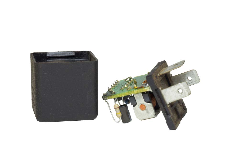
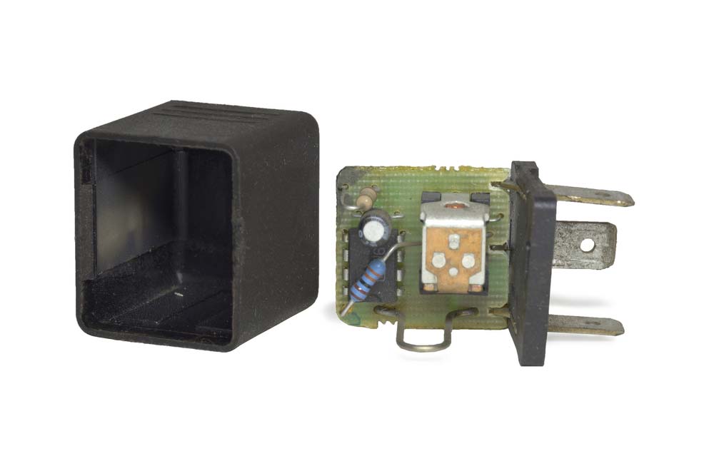
A car relay (PCB-mounted)
In this setup, the secondary circuit has a switch normally open (NO) or normally closed (NC).
With the NO type, the coil closes the circuit when energized. But with the NC type, the coil opens the circuit when energized.
SPDT
Single-pole double-throw switches have two circuits on the secondary side (double-throw), which allows them to control two devices.
The NC side remains powered by default, but the contact switches to the NO side when you energize the coil.
This action turns off power flow to the NC side, diverting it to the NO side.
A 5-pin SPDT switch
DPST
Having double poles, each with a single throw, DPST is equivalent to two SPST circuits.
Therefore, this relay can power two devices concurrently.
Remember, SPDT relays can control two circuits but power only one at a time. But DPST PCB relays can power or turn off both concurrently.
DPDT
Double-pole double-throw switches are like two SPDT contacts in one device.
Therefore, these relays can control four circuits, where energizing the coil can power two NO circuits and turn off the other two NC contacts.
When off, the relay reverses the contacts, powering the lines off (NC) and turning off the NO contacts.
Special Offer: Get $100 off your order!
Email [email protected] to get started!
How Does a PCB Mount Relay Operate?
A PCB relay features a coil in the energizing circuit aligned with the contact points.
As current flows through this circuit, it creates an electromagnetic field that operates through the metal plate connected to the armature.
This magnetic field can shut or open the contacts, which is the switching effect.
You can then use the throw count, pole count, or break count to control the relay's contacts in several ways.
Relay Pin Terminals
Since there are different relay types, each has a unique set of pins. Electromagnetic or electromechanical power relays have the following four terminals. 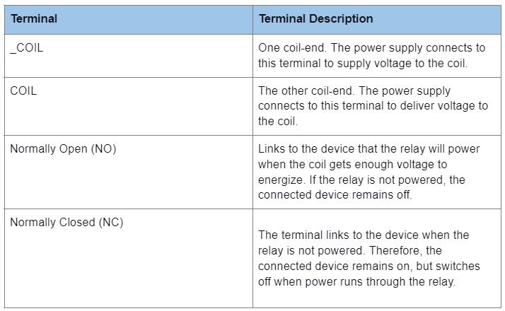 Reed relays have a similar design to the electromagnetic type and have positive and negative terminals.
On the other hand, solid-state relays contain input, load, and output terminals, while thermal relays have two terminals connected in series with motors. 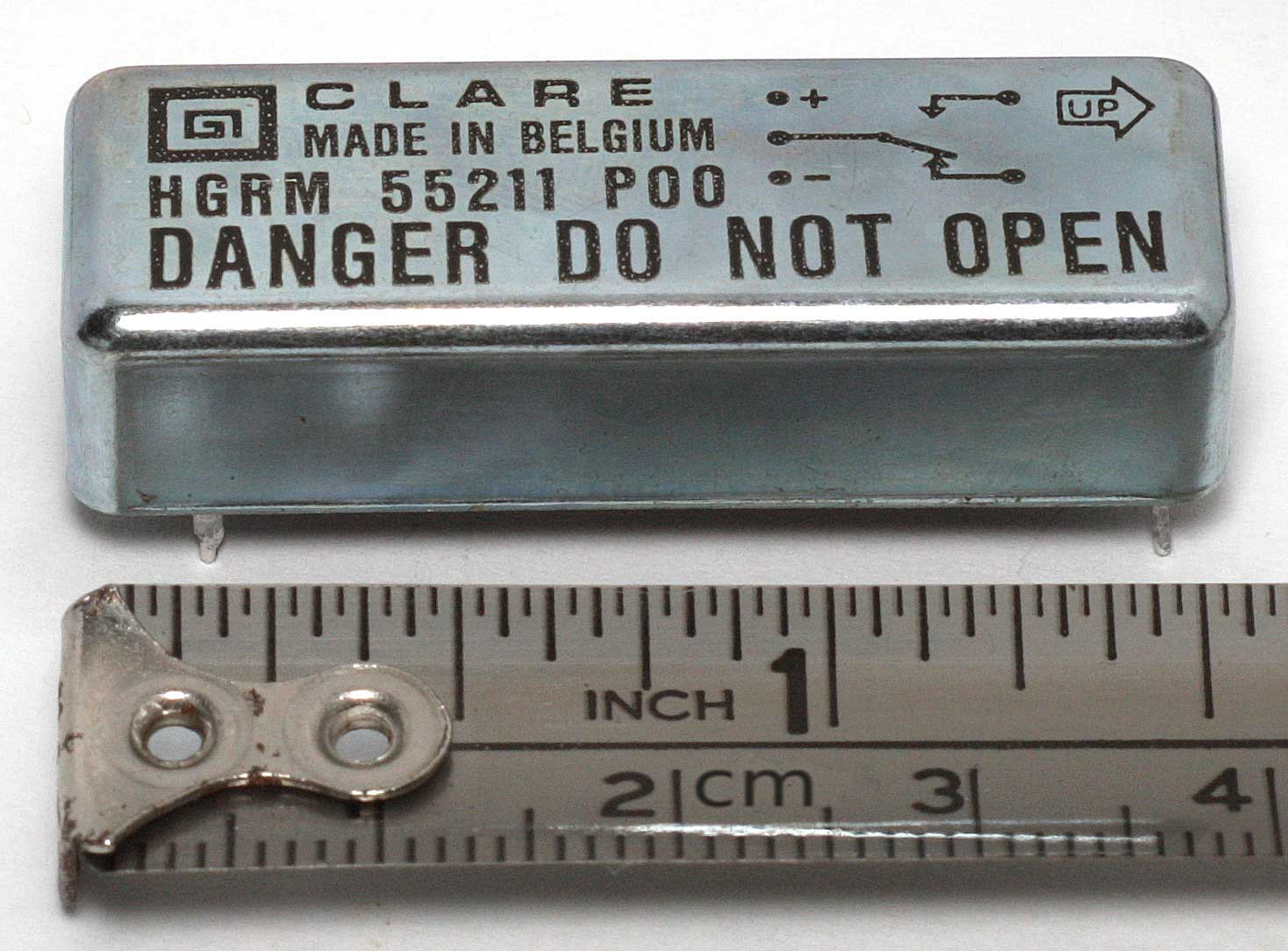 A reed relay Source: Wikimedia Commons
Common Applications of PCB Relays
- Household appliances and electronics like video game consoles and amplifiers
- Mobile/smartphone accessories and telecommunication equipment to control data transmission
- Surgery and medical instruments like ultrasounds and MRI scanners
- Military and aerospace systems in avionics, missile control, navigation, and more!
- Vehicle electronics for illumination switching, to control the powertrain, and to manage engines.
A relay mounted on a PCB for car function switching
- Industrial machinery and equipment to control heaters and motors
- Automated systems to control processes
PCB Relay Design Considerations
Consider these design guidelines to ensure the PCB relay remains reliable throughout its lifespan and functions optimally.
- Make the relay’s design simple and integrate it into the PCB’s design using an optimized connection that ensures dependable and consistent switching performance.
- Evaluate the required contacts for the circuit to reduce the relay’s pins as much as possible, which will increase efficiency. While these devices are reliable, those with more contacts have more points that can fail. And they are costlier, as well.
- PCB relays have operating current and voltage ratings, which should match the ratings on the board.
- Relays also have a maximum operating temperature range; you should design them to operate below what the PCB can handle. Also, consider positioning the device in a neighborhood that doesn’t have hot components. Alternatively, you can design the device to handle hot temperatures without failure if it will sit in a hot area.
PCB Design Requirements for Electromagnetic Relays
An electromagnetic PCB relay will not work if its internal mechanisms get distorted.
Therefore, you must pay attention to its soldering, washing, and heat application during the mounting process.
Most manufacturers provide recommendations for mounting relays, and they include the following.
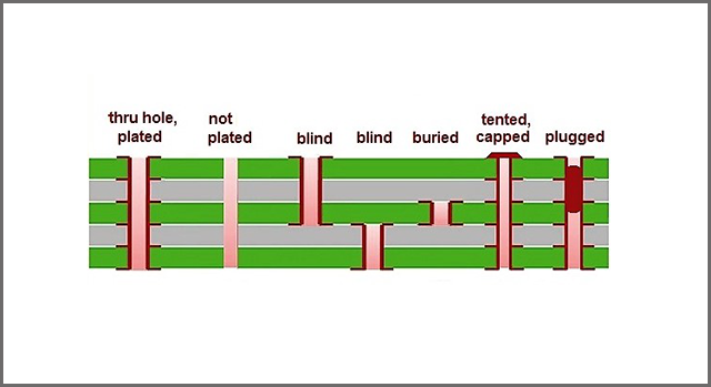
- PCBs made using paper-epoxy or glass-epoxy
- 1.6mm thick PCBs (for through-hole mounting)
The relays should also have the standard conductor thickness (35 and 70µm).
However, thermal and electromagnetic relays perform differently when exposed to heat and magnetic fields.
Therefore, you should remove them from semiconductors, transformers, and other heat-generating components during the printed circuit board design process.
Also, mount the relay to have vibrations or shock hit perpendicularly to the relay armature operating direction.
Types of Relay PCBs
- Single-channel relay board PCB
- 2-channel relay PCB
- 4-channel relay PCB
- 6-way relay PCB
- 8-relay board PCB
- 16-channel relay PCB (12V)
Attach the external devices like the load, power source, and Arduino board to the PCB, then test the circuit.
You can expand the code to add more control functions or design a circuit with a DPDT to control more devices.
How to Solder a Relay on a Circuit Board
Soldering comes after mounting, flux application, and preheating. You can either do this automatically or by hand. The following steps should guide you through the automatic soldering process.
- Adjust the solder level to avoid overflowing onto the PC board top using the flow soldering process.

A wave (flow) soldering machine
Source: Wikimedia Commons
- Solder at 500°F±41°F/ 260°C±5°C for about six seconds
Use these conditions unless specified otherwise, depending on the relay type. However, the relay's performance can degrade on multi-layer boards due to their high thermal capacity.
Therefore, take caution when using such panels. For hand soldering,
- Use a 30-60W soldering iron with a clean tip

A soldering iron
- Maintain the tip temperature at 662°F or 350°C
- Solder for about three seconds
After that, cool, clean, then coat the board.
How to Test a Circuit Board Relay
If you recall, NO contacts remain open with an unenergized relay, while NC contacts remain closed with an unpowered relay. You will need a multimeter for this test and use the following steps.
- First, set the multimeter to continuity check mode
- Test for continuity between the pole and NC contacts
- Check for discontinuity between the pole and NO contacts
- Energize the relay, which should engage and produce a clicking sound. Remember to use the rated voltage
- Then, check for continuity between the pole and NO contacts
- Next, test for discontinuity between the pole and NC contacts
- Lastly, measure the relay coil's resistance using the multimeter. Check whether this value matches the one labeled by the manufacturer.
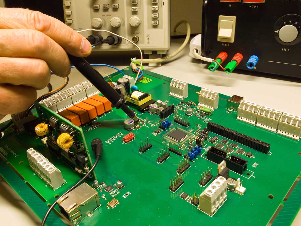 Testing a Circuit Board
Back to Top: PCB Relay
Special Offer: Get $100 off your order!
Email [email protected] to get started!