A MOSFET solid-state relay (SSR), sometimes referred to as an optical-coupled MOSFET, is an electrical switch of high power that operates without physical contact. As a result, it uses solid-state semiconductors such as MOSFETs to switch electrical loads.
Mostly, SSRs are suitable for operating high-power AC signal and DC signal loads. And compared to power/electromechanical relays, they are more efficient due to distinct features.
For today's post, we will expound on the basics of an optical-coupled MOSFET relay. Then highlight its features, structure, and applications. Also, we will discuss how the SSR differs from a power MOSFET.
Contents
- MOSFET solid-state relay Structure
- MOSFET solid-state relay Features
- Low malfunction rate
- Large Current (AC) and High Voltage level
- Operation on high speed
- Consuming low power and high voltage sensor
- Reduced operation noise
- Lightweight and small size
- High reliability and insulation
- Resistant in vibration and shock
- Temperature and linearity
- MOSFET Solid-state Relay Applications
- Basic SSR Working Concept using MOSFETs
- Difference Between MOSFET Solid-state Relay and Power MOSFET
- Conclusion
MOSFET solid-state relay Structure
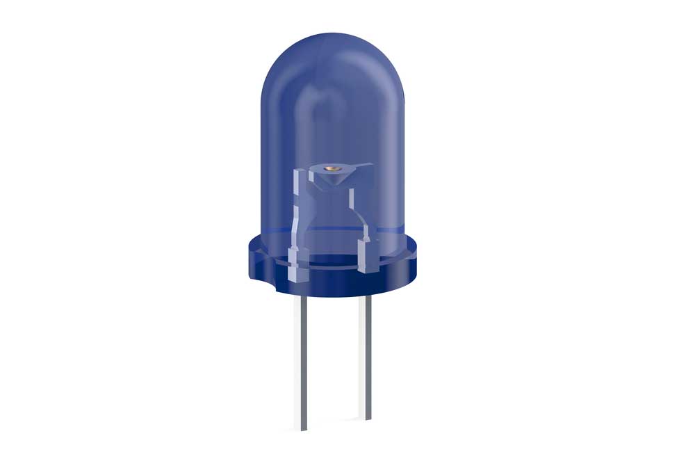
An SSR has a LED on the input side, MOSFETs, and a photo-voltaic diode (PVD) that faces the LED, which makes up its structure.
(LED)
- Input light-emitting diode; when forward current flows through the LED, it majorly produces an infrared LED. Then, the light shines on the photo-voltaic diode that later causes a voltage generation. Afterward, the MOSFETs gate (or photodiode array) receives the output voltage and makes the MOSFET switch on and off the drain current.
- What's more, an SSR has two MOSFET types; ON/depletion type and OFF/ enhancement type. You can turn the depletion type into a B/break contact type relay, and you can do it by ensuring the connection generates a negative gate voltage. Conversely, you can turn the enhancement type into an A/Make contact type relay. Here, you'll need a connection that produces a positive gate voltage.
-
In addition, an optical-coupled MOSFET relay can have an internal drive controller.
- When there's no light emission from the LED, the controller will function to accelerate discharges from the MOSFETs gates. Hence, it promotes a smooth and reliable switching speed during the operation. Also, the controller ensures good linearity during conduction and exceptionally high characteristics in the reverse and forward direction.
- Furthermore, an optical-coupled MOSFET has two molding structure types; high insulation and primary standard types.
- Finally, a high transparency insulating resin insulates both the photo-voltaic diode and the input LED on the output side. Further, the exterior has a black-colored resin cover that helps the MOSFET operate steadily despite ambient brightness.
MOSFET solid-state relay Features
The features of solid-state relays with MOSFETs are as follows;
-
Low malfunction rate
First of all, SSR MOSFETs can tolerate fluctuations in the electric potential occurring between the output and input sides. Also, they lack the chattering that often appears in mechanical relays. As such, the two factors above contribute to a low malfunction rate.
-
Large Current (AC) and High Voltage level
A MOSFET relay has MOSFETs for contact and photodetectors (for control signal) on two different chips. As such, it makes it simple to build a MOSFET that can regulate large current or high AC voltage via a selection of required MOSFET chips. What's more, the chips have a serial connection in reverse for the contact. In other words, you can switch both direct current and alternating current on and off as you wish.
-
Operation on high speed
Optical-coupled MOSFETs function using electrons and light; hence their operating speed will always be ten times quicker than mechanical relays. The high-speed operation is, therefore, applicable in semiconductor testing equipment or products that need high-speed.
-
Consuming low power and high voltage sensor
CMOS logic gates often directly drive the optical-coupled MOSFET because the input side lacks an induction and has a low driving current (few mA). Due to that, you will have a simple external circuit. As a result of the low power consumption, you will find that the SSR MOSFET is effective for applications such as power saving in battery-driven laptops.
-
Reduced operation noise
SSR MOSFETs don't produce noise during operation. Therefore, they are suitable in homes, plants, and offices where you need low noise levels. In addition, they don't generate contact sparks. Consequently, radio frequency in audiovisual equipment runs smoothly without interference. Also, you won't need to worry about applying extra stress on the parts under testing.
-
Lightweight and small size
An optical-coupled MOSFET comes in ultra-small flat-lead and small-outline packages (SOP). The size and lightweight ultimately make them an ideal choice for electronic equipment. For example, you can see them in semiconductor testing equipment with high-density mounting and laptop computers.
High reliability and insulation
An optical-coupled MOSFET uses an optical connection to have complete electrical insulation between the output and input. Furthermore, they can also be semiconductor devices such as memories or microprocessors. Therefore, they are less likely to have mechanical wear off and suffer mechanical contact degradation during their switching function.
Resistant in vibration and shock
Optical-coupled MOSFETs are highly resistant to vibration and shocks since they lack moving parts and metal contacts that are prone to physical vibration- and shocks damage. Therefore, they are suitable for automatic testers and portable audio devices.
Temperature and linearity
The contact MOSFETs on the output side have efficient linearity in the reverse and forward direction. Hence, they are ideal for use in minute input analog signals. Also, the ON-resistance in SSR MOSFETs fluctuates a little, stably, over a wide range of temperatures.
Special Offer: Get $100 off your order!
Email sales@ourpcb.net to get started!
MOSFET Solid-state Relay Applications
SSR is a commercial device that is recommendable in a wide range of applications such as;
- HV or AC systems,
- Thermostats,

- Building industrial automation,
- Electrotechnical (EMR) replacement,
- Instrumentation systems,
- Programmable logic controllers,
- UPS,
- Automatic test equipment, and
- Battery management systems.
Basic SSR Working Concept using MOSFETs
Required components for the basic working of a MOSFET include;
- MOSFETs – T1 and T2,
- Internal diode – D2 and D1,
- Input DC supply,
- MOSFET on and off switch,
- AC supply, and
- A load.
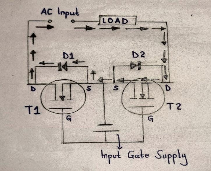
In a simple solid-state relay design guide, MOSFETs T2 and T1 have a back-to-back connection with the gate terminals and have source pins joined together.
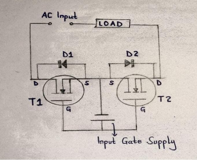
A Simple reference design of a solid-state relay MOSFET
Then, D2 and D1 represent MOSFETs as internal diodes. Further, if need be, you can reinforce the diodes with external parallel diodes.
Also, an input DC power supply triggers the MOSFET ON or sometimes enables a constant MOSFET switch ON while the optical-coupled unit works.
Finally, there are AC supply voltages that go up to the level of GRID mains. Here, the loads have a series connection across the two MOSFET drains.
Working principle
First diagram on working of a MOSFET
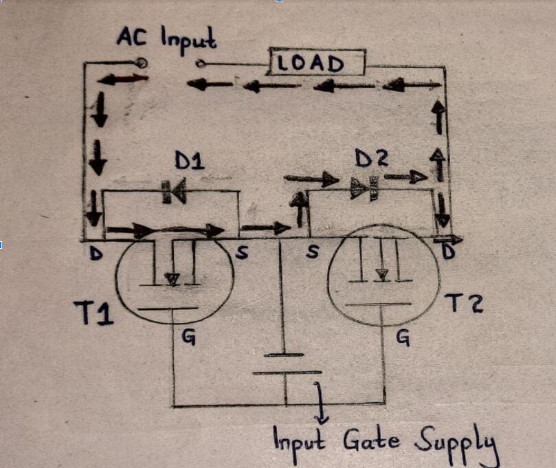
The second diagram on working of an SSR
The setup above illustrates how an optical-coupled MOSFET works with the following procedure;
- First, T2 and T1 are in switch ON positions because of the input gate supply connection.
- Next, when you switch ON the load side AC input, you'll have the second diagram showing how conduction occurs via a negative AC cycle through the other diodes, that is, D1 and T2. On the other hand, the first diagram will show conduction via a positive half process through the diode pairs D2 and T1.
- Further on, in the first diagram, one AC half-cycle works through D2 and T1, while T2 is reverse-biased. Eventually, it results in a cycle completion through the load.
- For the second diagram, T1 is reverse-biased, then the other AC half-cycle conducts through D1 and T2 loads in the opposite direction, therefore completing the circuit.
In summary, T1 and T2 MOSFETs and D1 and D2 diodes allow AC conduction in both half cycles. Consequently, the AC load gets powered and effectively culminates the SSR role.
Difference Between MOSFET Solid-state Relay and Power MOSFET
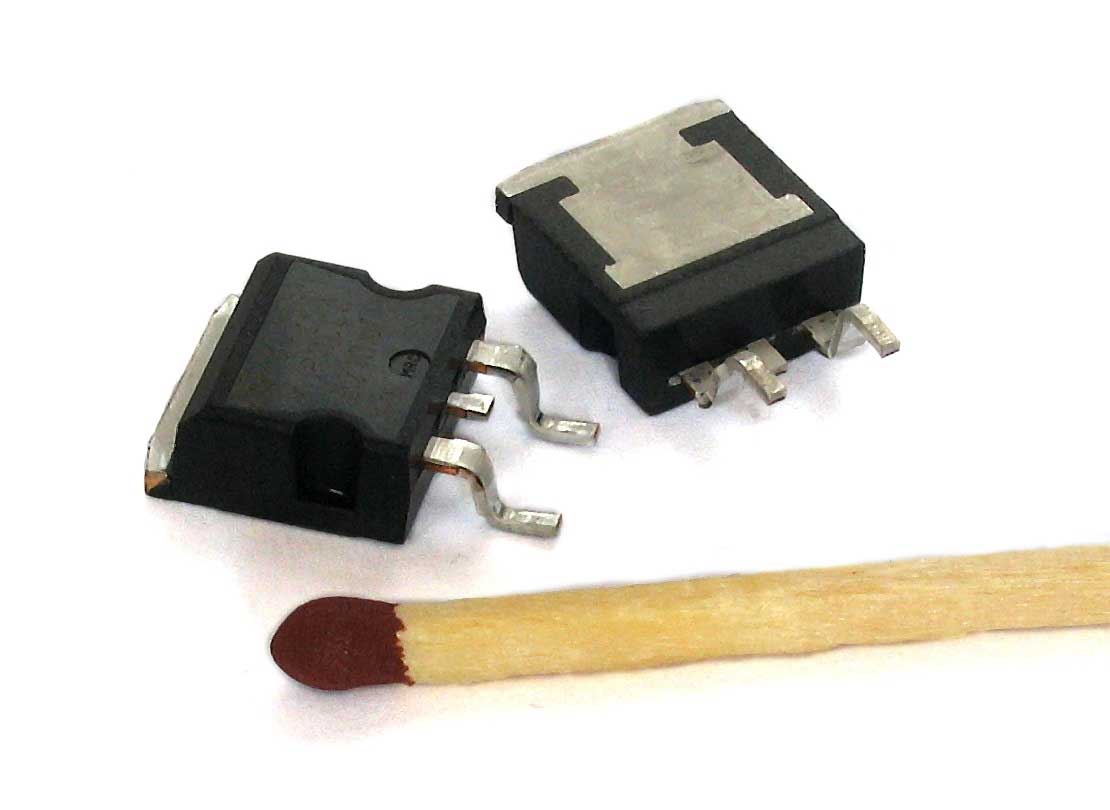
(power MOSFET)
| Feature | MOSFET solid-state relays (SSR) | Power MOSFETs |
| AC/DC loads | An SSR has both AC- and DC- solid state relays. | A power MOSFET either has a DC load or an AC load. |
| Leakage current | It has a high leakage current, therefore, making the lamp light up dimly. | It has a smaller leakage current, such as 10mA maximum. Hence the lamp doesn't light dimly. |
Conclusion
To conclude, an optical-coupled MOSFET switches ON and OFF when you apply a substantial external voltage crossway to its control terminals. It works similarly to an electromechanical relay, and the only difference is better features and no moving parts.
Despite numerous advantages, when using an SSR, you should also consider its inability to withstand momentary overload and high ON-state resistance during its initiation.
All in all, we do hope you've grasped some concepts on SSR. However, if there's a need to discuss more technical knowledge on a primary MOSFET relay, you can reach out to us.
Special Offer: Get $100 off your order!
Email sales@ourpcb.net to get started!