Blog  /  PCB Artwork- Design Guidelines Every PCB Manufacturer Need To Now

PCB Artwork- Design Guidelines Every PCB Manufacturer Need To Now

Do The Complex Measurements Involve In PCB Artwork Designing Befog You?
Alternatively, Do You Know You Can Create A PCB That Can Enthrall Your Audience Making Them Burst Out Laughing?

An entirely new level of innovation is involved in PCB artwork; you need to dig in more or get expert assistance to help you take the lead.
PCB is on the rise these days. As technological advances flourish, many tech giants have introduced devices with complex technicalities and reduced sizes.

When every other designer strives to beat the best, there arises a need to get a better grip on the complex functions involved in PCB artwork, including the need to choose the right thickness to the use of Copper-to-Edge Clearance.


Special Offer: $1 for 5 PCB Assemblies!

One requirement only: Order must be placed using a company account.
Please email [email protected] for details.

1、What Is PCB?


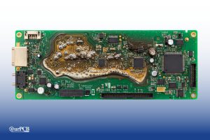
PCB, abbreviated as Printed Circuit Boards, constitutes essential components in many electrical devices. Its manufacturing involves an array of sophisticated functions, including the use of plates, screens, dimensions, and profound knowledge about blending the different elements to make the circuit work.


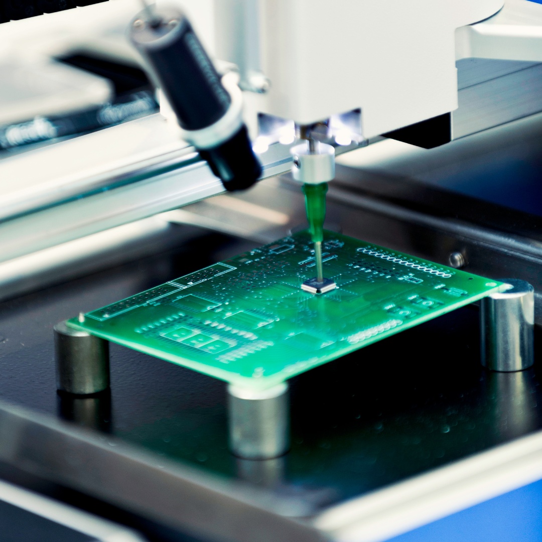
PCB ArtworkImage 1: Printed Circuit Board


1.1 Composition of PCB


The PCB boards involve some copper traces layers laminated together to connect with FR4, thin copper foil, Soldermask, and Silkscreen. The process of making the design and completing the circuit predicts the functionality and performance of the course.

Such a vast array of functions and steps involved in the creation gives rise to several issues.
Usually, novice designers get caught in assembling the different parts and making the correct measurements.


1.2 Scope of PCB Artwork


PCB Artwork has its roots in the advanced technological fields to simple DIY techniques. Where experienced designers and developers are infusing complex functionalities to create smart wearables and ultra-technical devices, people also incorporate the PCB processes and technologies to manufacture small daily use items and stuff on a smaller scale.

iPhones, one of the most commonly used smartphone, involves the latest versions of PCB. It has such mini boards that are in reduced sizes and are backed up with complex functionalities. The PCB boards have made smartphones perform much more efficiently and do functions that were never expected. Similarly, the rise of wearables depicts the use of similar PCB techniques.

Furthermore, the fun side of PCB usage is that it can help you create artwork that can enthrall your audience. You can use it in your DIY techniques and make cool keychains, birthday presents, household items, organizers, and many more by adding a spark of technology.


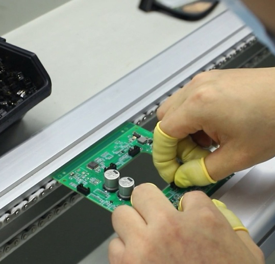
PCB ArtworkImage 2: Scope of PCB Artwork


1.3 How are PCBs Manufactured?


When using PCB artwork, you need to have an idea about an appealing product. Once you know what to design, you have to begin the process with a few necessary steps as listed below:


Convert PCB Design to Photo Films


The transfer of artwork involves printing the PCB schema on one or more films. Once you create the movie, it is then converted into actual boards, which have different films for each physical component of the PCB.


Transfer Films onto Copper


The second step involves the transfer of films onto copper. It is a multi-step process in which you have to clean the copper, transfer the design films, and zap it using UV light and wash off the unwanted copper using chemicals. After fusing, drilling and plating, you can be sure that your PCB can conduct electricity in just the way you want it.


Solder Mask Application


You need to apply the solder mask using UV lights and special inks.


Surface Finish


Ensuring easy solderability, the designers plate the PCB with silver or gold.


Silkscreen


Silkscreen enhances the entire PCB functionality. It is used when you print the electrical information onto PCB.
Once you are through these steps, there comes the time to get your hands dipped in the PCB scanning task.


PCB Artwork


2、PCB Artwork Scanning-Convert Any Artwork Efficiently


2.1 How to scan PCB artwork in Gerber files?


Upon completing the PCB electrical Artwork design, you need to convert your system into Gerber files to have a digitalized version of your creation. Gerber files are the universal language. It helps the PCB artwork print devices read the information by converting the content into one of its files.


2.2 Gerber Files


To describe each one of the layers present in the PCB artwork, the 2D vector illustration is used, which is called Gerber Files. For instance, one file will denote the Silkscreen while the other one will describe the copper layer. These general files include two types, namely RS-274-D and RS-274-X. Among these file types, the former requires D coding to elaborate the graphics involved, whereas the latter consists of D-coded files.


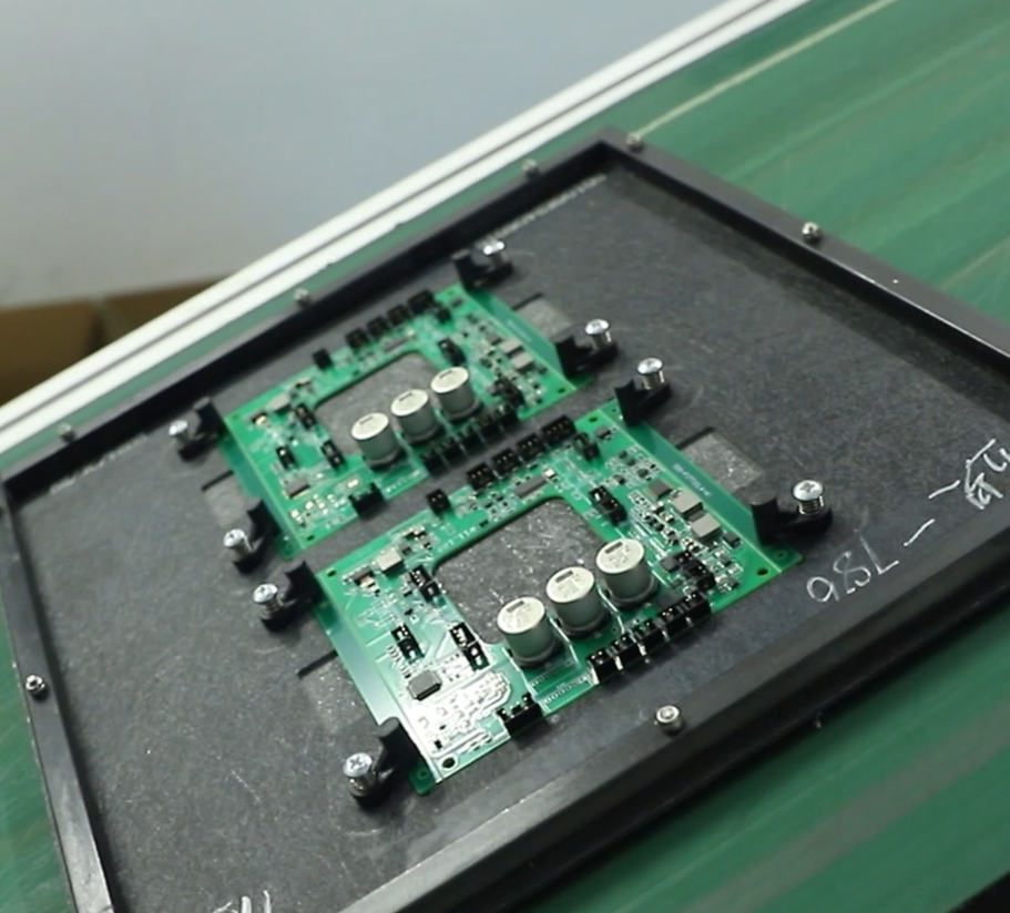
PCB ArtworkImage 3: Gerber Files


2.3 Instructions for Conversion


A step-by-step guide to convert your content into Gerber Files


Step#1: Install A CAD Software


You need to install professional CAD software if you want to get your PCB content digitalized. Over the internet, some CAD software is there that can assist you with this task efficiently.


Step#2: Open the CAD Software


Open the software and note the [Deleted:importa]essential tools present in it before proceeding.


Step#3: Upload the File


You need to select your PCB file, the one you want to convert into Gerber Format. You can choose the "import file" option present in the drop-down menu.


PCB Artwork


Step#4: Select the Gerber File


The next step involves the selection of a Gerber file. The option is present as an "export format" in the drop-down menu. Note that you must leave the choice of "Skip Options Dialog' unchecked.


Step#5: Import Options


In the window of 'GDSII Import Options', a window will pop up in front of you in which you have to check the option of 'Ignore Text.'


Step#6: Conversion Requirements


You have to configure all those options that are involved in your conversion requirements. The menu will appear on the screen, where you will be required to set the desired choices.


Step#7: Selection of PCB File


Coming towards the end of the process, you have to select the PCB file to convert and click it open.


Step#8: Conversion Process


After uploading your file, you have to click the "Next" button upon which the conversion begins. After completing the conversion, a new Gerber file will be uploaded to the same location where your original PCB file was present on your hard disk.


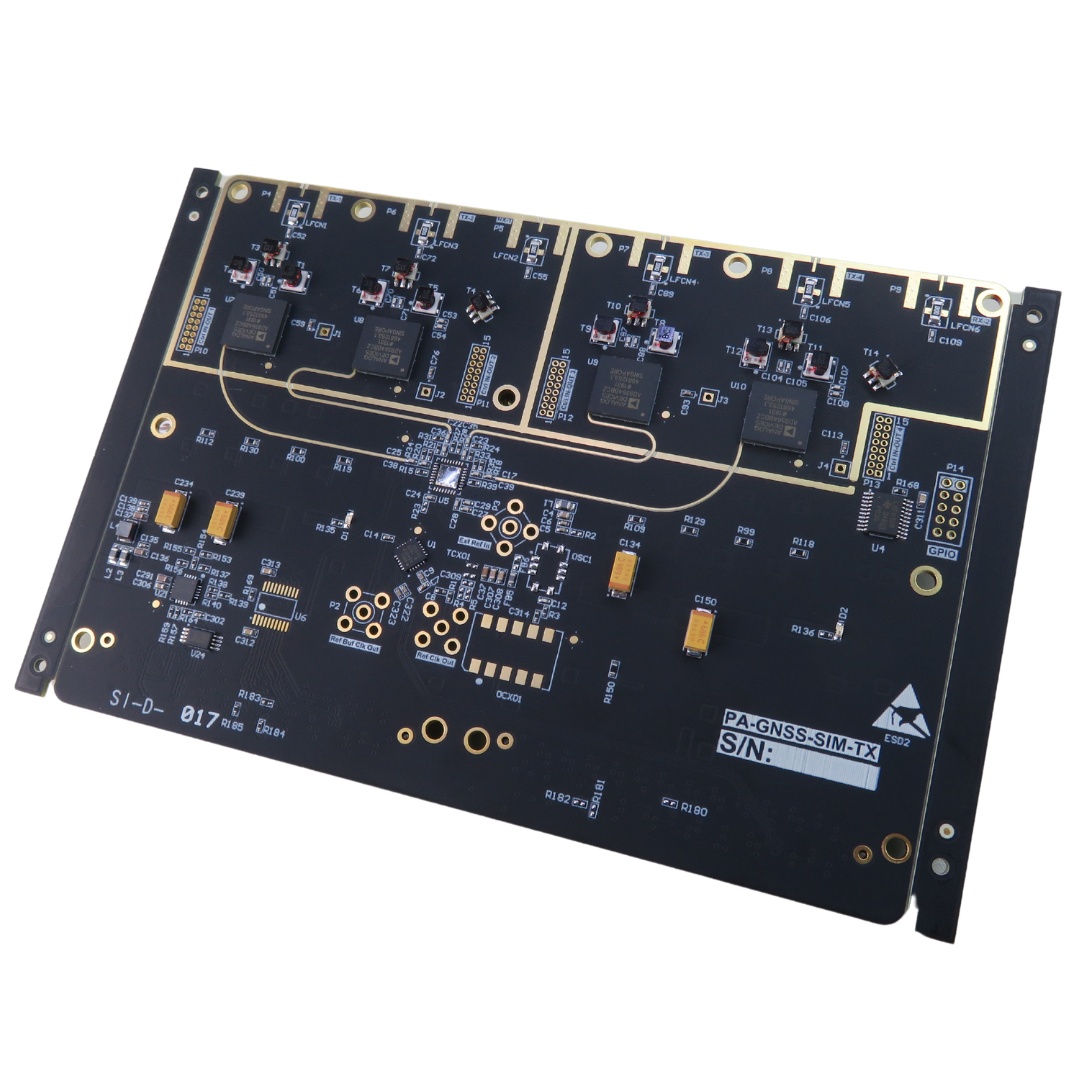
pcb artworkImage 4: Rigid PCB Board


Special Offer: $1 for 5 PCB Assemblies!

One requirement only: Order must be placed using a company account.
Please email [email protected] for details.

3、An Introduction to the Types of PCB Artwork


We live in a technology-driven era in which dozens of circuit boards surround us. However, did you ever wonder how many printed circuit boards we interact with? It's funny to know that you have to count on many PCBs to do your everyday chores, from the time you wake up until you fall asleep.

From being present in your television remote to operating your electric razors, PCBs are everywhere around you.

It was a simple glimpse of the broad application of PCBs. Manufacturers have to choose a different kind of PCB for the various categories of products. When planning to create a PCB board, you must learn about the many types of PCBs, so read in the following guide:


Single-Sided PCBs


This type of PCB involves a single layer of a substrate covered by a metal layer. Usually, copper is preferred for protecting a single side of the material, with a protective solder mask on its top. The final element is the Silkscreen is used to mark the individual parts of the board.


Double-Sided PCBs


The double side print circuit boards are commonly used. Its manufacturing involves a substrate, which has both sides layered with metal. Holes in boards allow the connection of the circuit present on one side with that of the other. Usually, one of the two technologies is involved in making the relationship- the hole-technology or the surface mount technology.


PCB Artwork


Multilayer PCBs


Much modern manufacturing of double-sided PCB is seen in the multilayer PCBs. It involves several layering systems with the use of insulating materials too. Usually, multilayer boards consist of 4, 6, 8, or 10 layers. This type is used to manufacture large devices like computers, medical machinery, and many more.


Flex PCBs


Inflex PCBs, flexible plastic is used as a substrate, which helps them create a board that can bend without breaking. It is time-consuming to produce than any other rigid board but has many advantages.

Apart from these, Rigid-Flex PCBs and Rigid PCBs are also used to create some fantastic electrical boards. PCB artwork design techniques are a bit complex. It involves rules and guidelines, which a designer must follow to produce a successful artwork.


pcb artworkImage 5: PCB Design Artwork


4、PCB Artwork Design Guidelines


The printed board circuits are the backbone of highly technical devices. It supports the manufacturing of nearly every giant technology present today. Its production involves several steps and processes, es along with tricky rules to follow.

The role of PCBs in electronic devices is to provide an electrical route to the signals that satisfy the electrical and mechanical requirements of the device, let's say, a digital clock or a calculator. Every single element present on the board exhibits an individual role and performs a unique purpose.

The most common software involved in PCB design manufacturing is KiCad, OrCAD, and Altium Designer. Once the design is created, it is transferred to the universal language that is a Gerber format. It helps the users to read the file digitally on professional software like CAD.

Phot films of the PCB are created using laser scanners to deliver an advanced and detailed film of the PCB artwork design. Each layer of a printed board has its film report, which represents the different sections present.

For example, black ink is used to show the conducting areas of the copper metal, whereas the remaining parts present the non-conductors. The same goes for the film having a solder mask.

Once the components are adapted and placed in their right position concerning the schematic produced by the CAD software, designers carry out the wiring. The PCB netlist wires a footprint.


Image 6: PCB Design


To keep the board's structure perfectly aligned, you need to place copper onto the surface, which goes into the newly drilled holes.


These copper traces are used to create a link between the different components, and finally, the PCB artwork is produced.

After the initial copper plating bath, the components inside the board get tin-plating, which helps in removing the excessive copper present. This action is performed during the etching process, in which the etching process helps remove the copper foil from the panel.

Furthermore, after the final etching process, the solder mask application is carried out on both sides of the board with a spark of UV light. The PCB designers apply the final surface finish, followed by the Silkscreen.

After completing the necessary design procedure, you must check the performance of your PCBs through a series of electrical tests. In this part, a technician has to perform an electrical test on your PCB. The automated procedure is carried out that delivers the report about the functionality of your device. Please take it as a final precaution to ensuring the highest productivity and premium quality performance assurance.

You have to get your hands on some advanced software and tools to confirm the level of efficiency of your creation. Electrical testing is known as Flying Probe Testing that involves moving probes for determining electrical performance.

That's how the entire PCB artwork is designed; however, there are a few essential rules you need to take a look at.


PCB Artwork


5、PCB Artwork Rules and Recommendations


You know how tricky it is to manufacture the entire PCB artwork, but what if you think you have placed every component correctly, but still, your final product shows an inability to perform well. The tip here is to list possible dos and don'ts that can assist you in giving the last finishing with exact measurements followed by the right procedure.

You must know the ratio between the current and the voltage and the distance between the various layers. Each of these plays a vital role in making the current flow at a standard rate. The difference between the voltages of the different tracks determines the clearance present between the conductors.

If you ignored making the clearance, your PCB might result in a power breakdown or a short circuit. It will eventually ruin your efforts and can cause a functional failure. The safety precautions are to learn about eh different distribution of ratios as per the model.


Tracks Restricted Area


In the manufacturing of PCB, holes are drilled on the outside spots that are prone to get scratched or cracked. These areas or sections are used to transport the printed circuit board from a single process to another in which conveyor belts are used.

Hence, the track must not be located in all such areas as it can easily be peeled off, damaging the entire infrastructure. Therefore, in the areas where holes used for mounting the PCB spacers are drilled, tracks should not be placed.


pcb artworkImage 7: Tracks Restricted Area


Recommended Thickness & Width of Conductors
A specific ratio between the thickness and width is followed to determine the amount of current carried through the PCB conductors. According to the IPC standard, a rate of 1 oz/square feet between the conductor's breadth and depth is selected. Though, depending upon the functionality ad requirement of the board, a higher ratio is also chosen, which can be around 2 to 3 oz/square feet.


pcb artworkImage 8: Recommended Thickness & Width


Recommendation for Electrical Clearance
To protect PCB users from electrical hazards, we usually recommend a standard clearance of 8mm. You must as well keep the clearance between adjacent tracks as suggested by the legal IPC recommendations. Moreover, if you want to avoid performing these clearances, you can go for coating the PCB.

Many designers prefer coating the surface to reduce the need for adjusting clearance. In this case, the material used in the coating process is essential. If you use low-quality or inappropriate material, you can damage the flow of current through your device.

Therefore, it's best to stick with the standard clearance requirements and follow what the experts guide you. Learn about the clearance requirements from the table shown below.


PCB-ArtworkImage 9: Recommendation for Electrical Clearance


6、Conclusion


That was the entire PCB artwork procedure, from the tips to assemble components for scanning the films to fixing the clearance requirements. As you see, PCB Artwork is not child's play, so you need to back yourself up with a great deal of expertise still; you may not be able to produce a flawless circuit.

To assist designers in manufacturing top-class PCB artwork, we extend our support and deliver durable, reliable, and top-notch quality PCBs. If you want to have the most exceptional PCB prototypes along with some cool custom printed circuit boards, you can contact us freely and get in touch with us.


Special Offer: $1 for 5 PCB Assemblies!

One requirement only: Order must be placed using a company account.
Please email [email protected] for details.