As the name implies, the motion sensor circuit checks the direction of motion of people moving within a range. To build motion sensors, you can use several components such as PCB. But using the PIR motion sensor with Arduino is quite simple. Apart from that, the process is cheap, low-power, easy to build, and durable.
For this reason, many people use it for several applications, such as outdoor security lights in the home. That said, this instructable discusses how to build a motion detection circuit using passive infrared to switch on outdoor lights. We’ll further discuss the several applications of self-powered motion sensors.
Contents
- 1.What is a Motion Detector Circuit?
- The Active Component of a Motion Detection Circuit
- PIR Sensor:
- Phototransistor :
- 3.How Does a Motion Sensor Circuit Work?
- 4. Motion Sensor Circuit Schematic Design
- 5.How do You Make a Motion Sensor Light Circuit?
- Materials
- Tools
- Step 1: Setting up the breadboard
- Step 2: DC/AC conversion
- Step 3: Timer circuit
- Step 4: PIR sensor
- Step 5: AC pass through and relay
- Step 6: Construct and Finish
- 6. Application of Motion Sensor Circuit
- Conclusion
1.What is a Motion Detector Circuit?
A motion detector circuit detects any movement or motion. It has a built-in motion sensor, light sensor, temperature sensor, and most importantly, ultrasonic sensors. The circuit not only detects movement but also activates alarm signals and lights. Today, many people use the motion detector circuit to ward off intruders.
For instance, by placing it at your door, it’ll trigger an alarm whenever people walk through it. According to the circuit, it detects people and animals are moving to give an appropriate output. Generally, the motion detection circuit comes with various sensors like microwave and the passive infrared sensor. The circuit with a microwave sensor recognizes the movement of people by measuring the change in a frequency beam.
Meanwhile, the simple motion detector circuit with a passive infrared sensor detects motion using the human body heat. It’s also the most common circuit among industries because it uses an electrical circuit to pick up the movement of inanimate objects like a rolling ball. If a motion detector circuit has a strong connection, it will also pick up infrared heat.

(Black motion sensor)
The Active Component of a Motion Detection Circuit
Here are the active components of a motion detection circuit:
-
PIR Sensor:
The PIR sensor works to produce a frequency beam of infrared light. It has a wavelength that is undoubtedly shorter than microwaved but longer than wavelengths. Generally, the appropriate infrared wavelength is more than 6µm. We mean that the sensor has a wide-field motion sensitivity of over 20 feet and 70 degrees horizontally.
The PIR sensor often comes as a 3-pin device. Whereas pin 1 receives the base-emitter voltage. Note that the sensor requires power conditioning circuitry for operation. In this article, we’ll use 6V of power. You can obtain this by using a connected battery. At the same time, pin two works as the output module, while pin 3 is the negative voltage on the motion sensors.
Without the infrared transmission and source, the PIR sensor will not function as an active component in the circuit. The infrared source comes with inceptions such as black body radiators, silicon carbide, and tungsten lamps necessary for operation.
-
Phototransistor :
These transistors detect the direction of motion of any photo or body infrared radiation.
(Sports sensors and light bulbs)
Special Offer: Get $100 off your order!
Email [email protected] to get started!
3.How Does a Motion Sensor Circuit Work?
In the aspect of motion detection, the PIR sensor makes a high-frequency beam using the 555 timer IC to set the astable multivibrator at the section of the transmitter. The sensors further produce the frequency beam, which the photoresistor collects at the receiver section. During this phase, the power conditioning circuitry will not give any output.

https://en.wikipedia.org/wiki/Motion_detector#/media/File:Photospirp.jpg
(The most common type of motion-sensing device in the home)
However, where there’s any interruption between the transistor and the sensor, it creates an automatic light beam. The intrusion also makes the IC 555 timer trigger an alarm signal through a speaker. On the other hand, if there’s no intrusion, the phototransistor keeps pin 2 of the timer in a monostable manner. Plus, it won’t give any output to sound the alarms. Both the variable resistor and the capacitor determine the alarm time and prevent false triggering in the circuit.

(how motion detectors work)
4. Motion Sensor Circuit Schematic Design
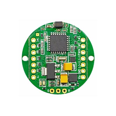
Here is the schematic design of a motion sensor circuit

(3D infrared motion sensor)
Source: Wikimedia
The image above shows the PIR sensor at the center of the circuit. You'll also see the various power pins and a LED that connects to the output pin. Whenever the circuit detects nearby motion, it powers the led, which works as exterior lights. After a few seconds, the LED goes off until it senses the activity of object motion.
5.How do You Make a Motion Sensor Light Circuit?
Below are simple steps to build dark edge motion sensor lights using the appropriate tools and materials.
Materials
- 1 IC 555 timer
- Printed PCB
- Resistors
- Capacitors
- AC voltage density regulator
- Relay coil
- 1 LED
- One potentiometer
- Four rectifying diodes
- 1 PIR sensor
- One fuse and holder
- Board pins (for connecting the cable wires)
- Wires, glue, heat shrink, screws as appropriate
Tools
- Analog input sensor discovery
- Pliers, wire cutter, and hobby knife
- Mounted breadboard power for testing
- Solder and soldering iron
- Digital multimeter
Step 1: Setting up the breadboard
Get a breadboard or, better still, a PCB alongside a few jumpers and wires for testing as you build the motion sensor. It’ll be terrible to notice an error after soldering. The breadboard again has subsystems broken into smaller bits. Ensure they all work together before connecting them as a big motion sensor circuit. That way, you’ll find debugging easier.

(Motion detector printed circuit board.)
Source: free SVG
Step 2: DC/AC conversion
At this point, you’re to reduce AC voltage density by a range of 10. Before proceeding to make the motion detector, your connections must be accurate. The capacitor maintains the voltage at a high level to give accuracy in motion detection. Furthermore, your input to the regulator must be higher than the output, or you won't get a stable outcome. For instance, you can use a 7812 regulator alongside a 12VDC.
Step 3: Timer circuit
Connecting a timer circuit is simple and easy. The circuit's push-button works as a trigger pin. Plus, it needs a low activation signal to give output. You can also use the resistor to keep the signal high whenever the sensor isn't producing signals.
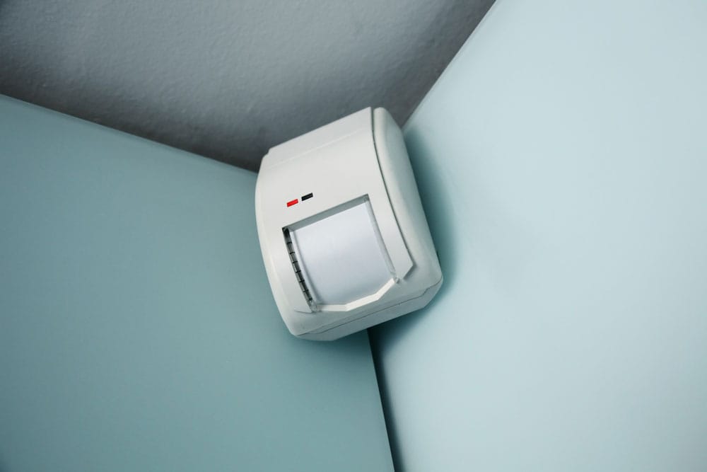
(White motion sensor)
Step 4: PIR sensor
Connecting the sensor is quite easy. Since it works perfectly with microprocessors, it only handles input. Therefore, using the resistors which form the divider reduces the power supply to the circuit.
Step 5: AC pass through and relay
Here, you’re to use the AC voltage during testing. Connect the AC outlet with a fuse to run power through it. As you build, ensure all the wirings have strong connections to one another. The power you supply depends on the application of the motion sensor. For example, if you’re using it for Christmas lights, you need low power. However, if they’re for exterior lights, you’ll require more energy.
Step 6: Construct and Finish
Using the diagram, remove the negative component of the wave then regulate it to a stable voltage. Besides, it’s essential you out for space limitations while you solder the parts to the PCB. The AC outlet should also have holes by the side for easy mounting to the case.
If these steps and movements do not trigger the sensor, go over it again. The problem may be that you soldered the wrong connections together. Or you probably forgot to feed the PIR wires through the circuit box.
6. Application of Motion Sensor Circuit
Today, it’s not surprising to come across exterior lights and alarm signals that trigger off with human movement. Fortunately, these are not the only uses of a motion sensor circuit. Several other applications include:
- People use motion detectors as security lights and intruder alarms in offices, shopping malls, banks, and homes.
- Industries also use it as a human detector in places that are out of bounds or restricted.
- They also function in energy efficiency structures such as the control and home automation system.
- Motion detectors again work as counting matches and automatic doors.
- Many shopping malls use them for automatic ticket gates and entryway lights.
- In toilets and bathrooms, they also function as automated toilet flushers and sinks.
- Besides, most big companies use them in hand dryers.
- Aside from producing energy, these self-powered motion sensors are indeed ambient energy sources. For instance, you can use them to save energy during the day to charge your appliances at night.
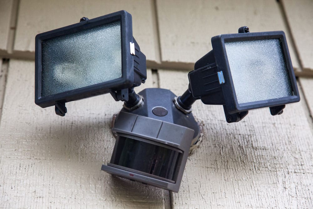
(outdoor security lights using motion sensor)
Conclusion
The diagram of the motion sensor circuit truly makes the construction easy to assemble. To build a motion detector light circuit, you’ll need LED. At the same time, for an alarm circuit, you’ll need a buzzer. Keep in mind that, despite how careful you are, mistakes may occur.
But in the end, you’ll find the process intriguing and insightful. Today motion sensors are an important element of the security and light system. With the instructions above, you can install it DIY.
Special Offer: Get $100 off your order!
Email [email protected] to get started!