If you are a robotics or electronics hobbyist, self-teaching can be a little tough. There is a surprising amount of jargon to learn. Working with electronics can be a fulfilling endeavor, but you will need to acquaint yourself with some of the equipment to be successful. This is even truer for students planning to become electronic engineers and designers in the future. Breadboard vs. PCB prototype are terms that you may have heard used interchangeably (erroneously). However, these devices are almost as different as day and night.
And this is the reason we took it upon ourselves to teach you the difference between a printed circuit board and a breadboard. Furthermore, this guide should help you decide which piece of equipment is suitable for your next project. At the end of this article, you may find yourself itching to design your very own PCB or breadboard.
Contents
- Breadboard vs. PCB
- Breadboard vs. PCB--What are Printed Circuit Boards (PCBs)?
- Breadboard vs. PCB-- What are Breadboards?
- Breadboard vs. PCB--How Do Breadboards Work?
- Breadboard vs. PCB: Comparison
- Breadboard vs. PCB: When to Use Each
- When Should You Use a Breadboard?
- Alternative to Breadboards
- When Should You Use a PCB?
- Final Word
Breadboard vs. PCB

In the following text, we will define what breadboards and PCBs are. We also explore how these two devices work and examine the advantages of each one. We end the guide by listing when it is appropriate to use each of them. Without further ado…
Breadboard vs. PCB--What are Printed Circuit Boards (PCBs)?

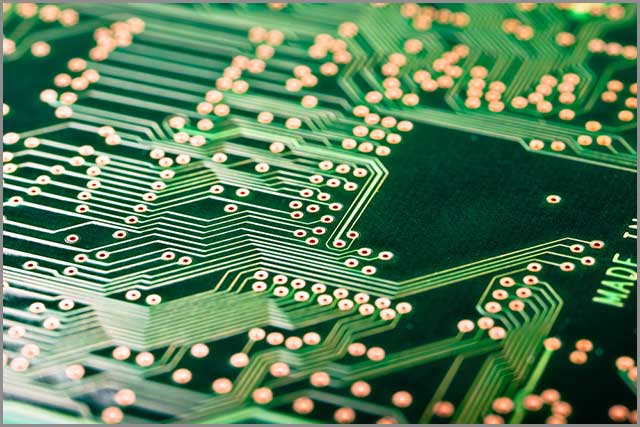
The easiest and probably the most ubiquitous example of a PCB is your computer’s motherboard. It connects and facilitates the communication between electronic components within your computer. It achieves this primarily through a collection of copper traces, tracks, and pads. Generally, in appearance, a PCB is a green layered piece of laminated board. Although, you may get in other colors.
The Austrian inventor Paul Eisler developed the first official printed circuit board in 1936 while working on a radio set. Companies did not manufacture PCBs regularly until the 1950s. The first PCB started with a single layer, but modern PCBs now consist of over twenty layers.
Before an engineer or fabrication company can fully assemble a PCB, it needs to be prototyped. This prototype will be a proof of concept, allowing you to test your design.
Nevertheless, Overall, as with your motherboard, the PCB is the carrier, foundation, and support for all your other devices within your system. You will find PCBs in smartphones, microcontrollers, smart TVs, etc.
Special Offer: Get $100 off your order!
Email [email protected] to get started!
Breadboard vs. PCB-- What are Breadboards?

In appearance, breadboards are rectangular plastic consoles perforated with square holes and engraved with various symbols and lines. Ronald J. Portugal invented the first solderless breadboard in 1971.
You may have heard it referred to as a solderless protoboard, plugboard, or terminal array board. It is uncertain where the name “breadboard” originates. However, we do know that electronic engineers in the past used to connect components by wire-wrapping them and nailing them into a wooden board.
Essentially, they would use these wooden boards as their bases. Another theory states that an engineer had an idea for a vacuum tube device once upon a time. The only thing he could use for the base was his wife’s breadboard. Therefore, breadboards may get their names from engineers using wooden boards to prototype their ideas.
The layout of a breadboard is quite similar to that of a PCB – at least in concept. The perforations on the breadboard allow you to connect various electronic components. These components can range from transistors to LEDs.
Not only do we use breadboards for prototyping, but we also use them extensively for educational purposes. In fact, in the same way, you can find build kits for your Raspberry Pi 4 project ideas, you can find various breadboard kits too.
They often come with power supply units, jumpers, wires, resistors, transistors, and other components. You can even connect them to PCB based microcontrollers.
Breadboard vs. PCB--How Do Breadboards Work?

Breadboards usually come in four banks of thirty rows of holes (sometimes six). In the two most central banks, you will find rows of five perforations. Each of the five/six holes in these rows connects through a set of metal strips. These rows are, however, electrically isolated from each other. We refer to these rows as nodes.
A grooved channel separates each of the banks of nodes. You will notice a set of rows running on the bottom and top (side) of the breadboard in most breadboards. Each column of two-hole rows is either positive or negative. You can discern this by the color strips running down the side of the columns. In addition to this, they have markings on either side of each column (+ and -).
We refer to these columns as bus strips. We generally use bus strips to connect power supplies. You can use them to modulate voltage levels in larger breadboards. Generally, larger breadboards are not actually singular breadboards but a series of connected breadboards.
The metal running through the bus strips connects horizontally while the metal connections in the center of the breadboard run vertically. The central nodes are where you will connect your electronic components.
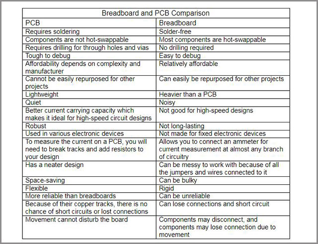
Breadboard vs. PCB: Comparison

In this section, we will discuss the advantages of each board. This should assist you in deciding which board is suitable for your next project.

Breadboard vs. PCB: When to Use Each

When Should You Use a Breadboard?
Again, if you are a novice hobbyist, it is always advisable to start working with a breadboard before you move onto more advanced projects. A breadboard is a great practical educational tool. It is a great way to test how electronics work.
A breadboard can be useful to professionals too. If you are designing a circuit and quickly troubleshoot and debug it, you can use a breadboard. It is well suited for experimentation and testing new ideas out. In addition to this, breadboards allow for quick and easy prototyping.
Alternative to Breadboards
The biggest issue that most designers seem to have with breadboards is their low current capacity. You could always use the Point-to-Point method as an alternative. The point-to-point method is where you connect and solder components directly without aboard. It is a little unsophisticated, but it does the trick, especially in simple systems. You can also try wire wrapping your components.
A perforated board is another good alternative to the breadboard. It is also known as a perf board or DOT PCB. As the name implies, a perf board is a thin piece panel that consists of lined up perforations. This is quite similar to the breadboard’s design.
However, often, the perforations have no electronic connections. Therefore, you may need to connect components through other means such as soldering or wire wrapping. Copper clad perfboards that have solder pads for each perforation are also available. Additionally, a few of these boards also feature a ground plane.
When Should You Use a PCB?
The most obvious alternative to a breadboard is an actual PCB. If you have a circuit design that you believe works, you may want to produce a PCB. This could be after you have tested the design on a breadboard.
You will want to use your PCB in a system such as an actual electronics device. It will often be the core or base of your project. Nearly all microcontrollers and shields are PCB-based.
Final Word
In this guide, we explored the differences between a Breadboard and PCB. If you have reached this section of the text, you should distinguish between these boards, how they work, and when to use them. We hope you have enjoyed reading this guide. Thank you for reading.
Special Offer: Get $100 off your order!
Email [email protected] to get started!


