Resistors are arguably the most typical components used in electrical circuits, and they play a critical role in diode circuits, such as rectifiers and LED strips. These resistors are known as current limiting resistors because of their role in those circuits. We will analyze these electronic components to show how you can calculate their ideal values for your project. Take a look!
Contents
- What Is a Current Limiting Resistor?
- Purpose of a Current Limiting Resistor
- Why Current Limiting Resistors Are Necessary for LED Light Circuits
- Causes of Burning Current Limiting Resistors
- Exceeding Its Capacity
- The Filter Capacitor Is Kaput.
- The Thyristor/Bypass Contactor Has Zero Action.
- Calculating Current Limiting Resistor Values for LED Circuits
- Single LEDs
- LEDs in Series
- LEDs in Parallel
- Current Limiting Resistor: Controlling Brightness
- How To Choose a Current Limiting Resistor
- How To Choose the LED Current Limiting Resistor
- How To Choose the Zener Diode Current Limiting Resistor
- Other Different Current Limiting Circuits
- Current Limiting Diodes
- Current Limiting Transistors
- Current Limiting Integrated Circuits
- Current Limiting Resistor: Circuit Design Steps
- Applications of Current Limiting Resistor
- Wrap up
What Is a Current Limiting Resistor?
A current limiting resistor is a resistor connected in series to a circuit for protection against excessive burning in the appliance. It operates on the principle of reducing current by increasing the overall load resistance.
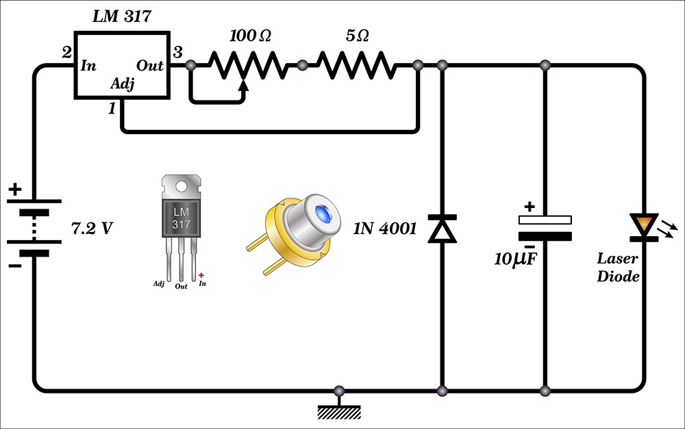
A current limiting resistor and a variable resistor in a laser diode circuit diagram
Most electronic components have a limit on the maximum current they can handle. If you exceed this current limit, the parts will not work and might burn out. So any resistor in series with the circuit regulates the current moving through, and you can refer to it as a current limiter resistor.
The device is typical in light-emitting diode circuits to protect them from burning out.
Purpose of a Current Limiting Resistor
These fixed-value resistors protect a circuit’s electronic components from excessive current flow. Transistors and LEDs are sensitive to current spikes, but these resistors regulate the current flow to keep it within acceptable limits.
Current limiting resistors can also stabilize the power supply voltage if it fluctuates.
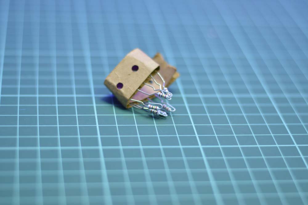
A set of resistors for current-limiting applications.
Why Current Limiting Resistors Are Necessary for LED Light Circuits
LED lights are some of the most fundamental output devices in open-source projects because they provide feedback on a circuit's status in an easy-to-understand manner. For instance, they can show when a device is on. However, connecting an LED directly to a power source will burn it out.
Here's why.
Resistors behave according to ohm's law (V=IR), which is linear. So if the resistance value remains constant, a voltage increase across the resistor will increase the current. And a voltage drop means lower current flow.
But LEDs don't operate like that. They are diodes and behave using the I-V curve. They have a recommended or characteristic forward voltage (usually between 1.5V and 4V) that you must reach to turn on the LEDs.
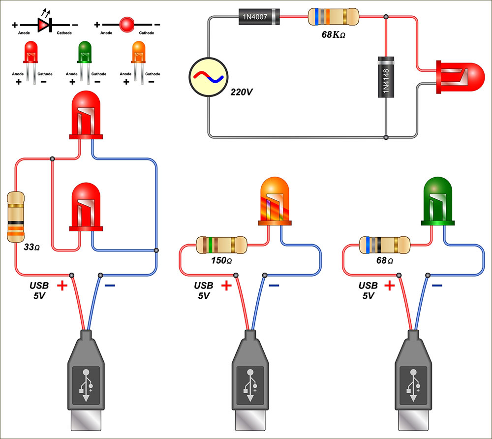
LED circuits with resistors
But once they turn on, the LED resistance drops quickly, and the diodes will allow high current levels to flow across. This excessive current will make them super bright and possibly burn out. A load resistor in series controls the current flowing through and protects the components.
Any circuit with diodes, like a rectifier, requires these series resistors for protection.
The alternative is to use a constant current LED driver, which produces a single current output while varying the voltage. But these drivers are expensive and have limited flexibility. So most people use constant voltage power supplies with current-limiting resistors.
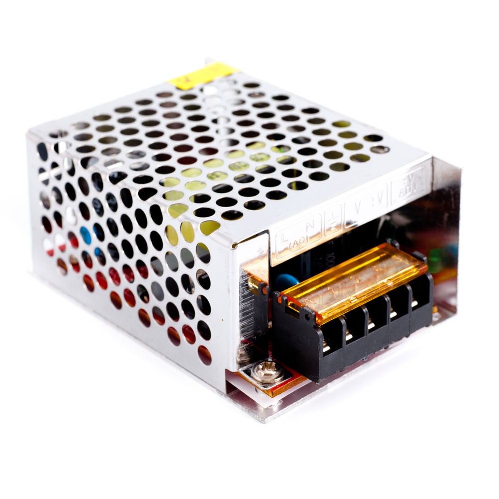
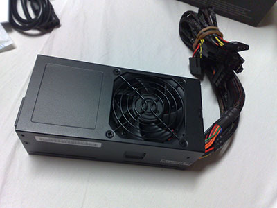
An LED driver
Causes of Burning Current Limiting Resistors
Exceeding Its Capacity
Exceeding a current-limiting resistor’s capacity will burn it. Some inverter manufacturers use small-capacity current limiting resistors to save on costs.
But, the current flowing in this resistor gets attenuated exponentially, and its duration is short. So you can use a small capacity current limiting resistor in circuits on one condition: it should correspond to the capacitor’s rating.
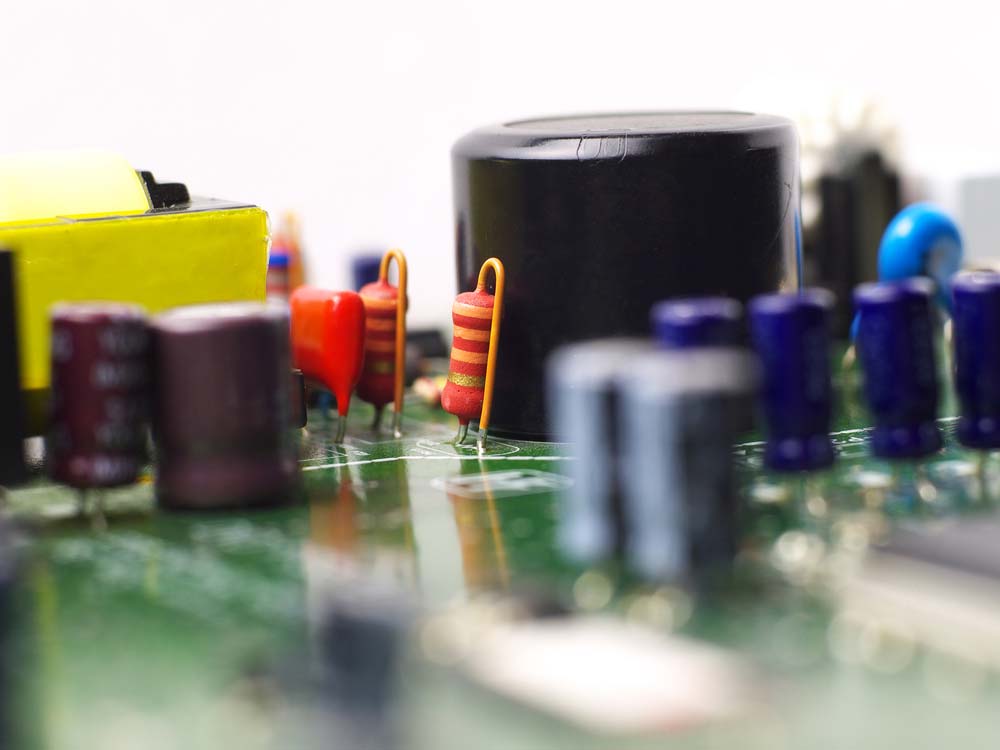
Resistors mounted on a circuit board.
These circuits have smoothing capacitors, and the larger the capacitor’s rating, the longer the duration of the current. So, you must adjust the resistor’s capacity accordingly to prevent burnout.
The Filter Capacitor Is Kaput.
Electrolytic capacitors tend to deteriorate if not used for a long time, and this can happen if you store the electronic product for a while without use.
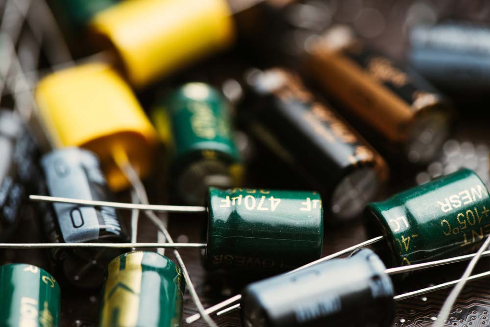
Electrolytic capacitors for future installation or mounting on circuit boards.
Should you bring the product back to life, the damaged electrolyte will cause leakages or short, resulting in voltage spikes that expose the resistor to current for a long time.
The Thyristor/Bypass Contactor Has Zero Action.
Bypass contactors act when the smoothing capacitor is charged to a certain point. If they fail, they expose the resistor to the circuit for a long time, resulting in failure.
A set of thyristors, which are basically transistors built for high-power applications.
You can test this thyristor by measuring the voltage across the current limiting resistor and the filter capacitor. If the voltage reading on the multimeter is zero across the resistor but the reading across the capacitor is large enough, you have a faulty contactor.
Special Offer: Get $100 off your order!
Email [email protected] to get started!
Calculating Current Limiting Resistor Values for LED Circuits
The best way to maximize the life of LEDs is to limit the current flowing through them. Here's how to calculate the correct resistor value for your project.
Single LEDs
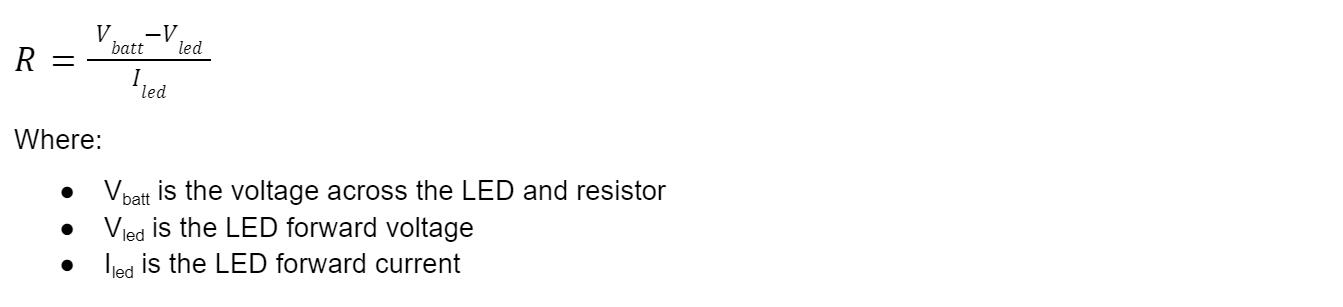
Ohm's law becomes a little complicated when calculating the current limiting resistor value for single LEDs, as shown below.
LEDs in Series
With LEDs connected in series, the formula becomes more complex because the voltage drop across them increases. And it drops the voltage across the resistor, as well. But the current across the resistor remains the same.
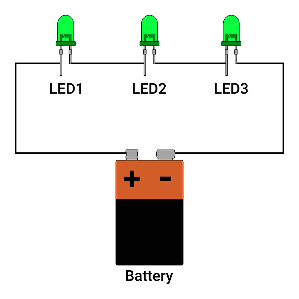
LEDs connected in series

Where n is the number of LEDs in the series.
LEDs in Parallel
When you connect LEDs in parallel, the current across the resistor increases, but the current flowing through each LED remains constant. On the other hand, the voltage drop through the resistor and LEDs remains unaffected.
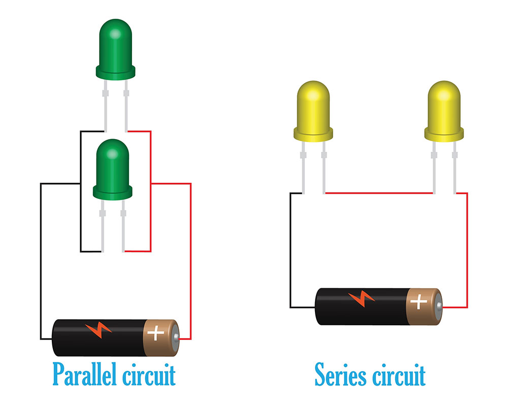
LEDs connected in series and parallel
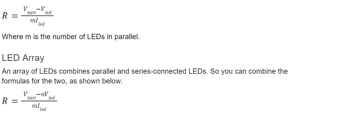
But it is vital to have n series LEDs in every parallel branch (m), and the units should have the same forward voltage and current. Otherwise, the formula will be irrelevant.
For instance, consider these four LEDs.
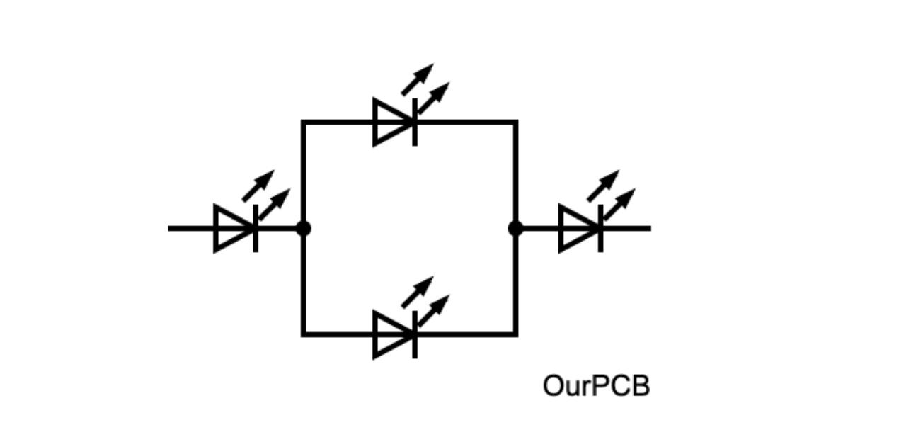
LEDs arranged in an array.
LEDs are arranged in an array.
The equation does not apply to the first circuit diagram but works for the second.
Current Limiting Resistor: Controlling Brightness
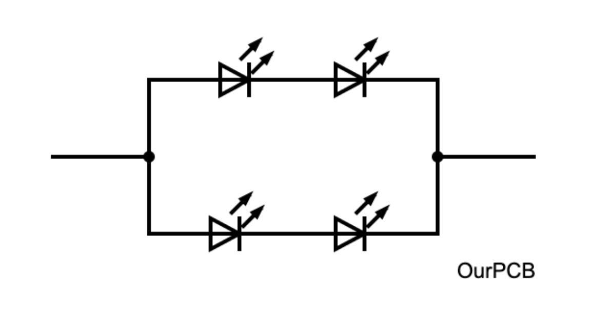
Some LED applications require dimming functions, such as in ambient lighting. This function requires two resistors.
- A fixed load resistor for limiting current (Rf)
- A variable resistor for brightness adjustment (Rv)
A variable resistor
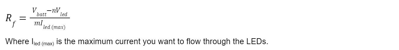
Rf limits current when Rv is at its minimum setting (0Ω) because maximum current flows across. So you can calculate the value of Rf using the following formula when Rv=0.
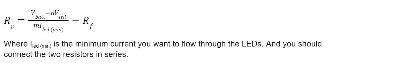
Adjusting Rv increases resistance in the circuit, lowering the current flowing across the LED. So it is lowest when Rv is at the maximum setting.
You can calculate the value of Rv using the following formula.
How To Choose a Current Limiting Resistor
We’ll focus on LEDs and Zener diodes.
How To Choose the LED Current Limiting Resistor
When dealing with LEDs, you must know the device’s operating current and voltage. Ordinary LEDs have a driving current of about 20mA, but the 0805 can go as low as 5mA. The high-power ones require at least 350mA.
However, the operating voltage depends on the LED’s color. For instance, the operating voltage for a red 0805 LED is 2V, and it increases to 3.2V for blue LEDs.

An outdoor board with a matrix of 4x4 LEDs.
With that in mind, you can calculate the current limiting resistor’s value using this formula.
R=U/I
Where U is the voltage drop across the resistor. So, if you’re using a 12V battery to power a blue 0805 LED, the voltage drop will be 12-3.2, which is 8.8V. The driving current is 0.02A. If you divide the two, you’ll get 440 ohms.
How To Choose the Zener Diode Current Limiting Resistor
Zener diodes operate as voltage regulators because as the load current increases, the resistor’s voltage drop decreases, which increases the output voltage.
This increase raises the current flowing through the Zener diode and its reverse voltage, as well. The result is an increase in the current across the resistor.
However, the formula for calculating the value of the current limiting resistor for this diode is the same as that of LEDs.
Other Different Current Limiting Circuits
Instead of resistors, you can use diodes, transistors, or integrated circuits to limit the current flowing through a circuit. Here’s how.
Current Limiting Diodes
You can connect a diode in series to the load in the circuit to drain the excess when it exceeds its threshold.
These diodes are JFETs with the gate shorted to the source, which leaves them with two terminals (source and limiter). This device allows current to flow through up to a certain level and then fall off if it exceeds this threshold.
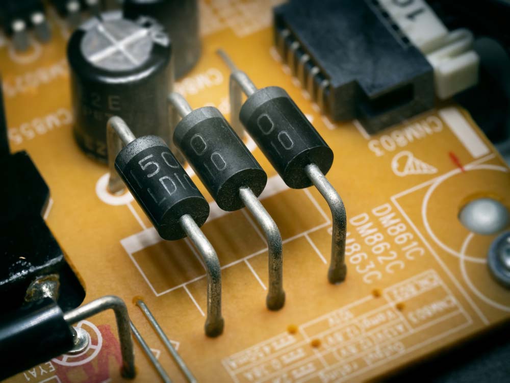
Three through-hole diodes soldered on a PCB.
Current Limiting Transistors
Transistors have three terminals and are common in foldback current-limiting circuits in advanced power supply systems. But you can also use one or two transistors in basic and linear power supply regulators, respectively.
Current Limiting Integrated Circuits
Instead of having separate or discrete components in the circuit to limit the current flow, you can integrate them into a chip. This packaged circuit is compact and smart enough to sense the current level in the circuit.

A semiconductor microchip mounted on a PCB.
Current Limiting Resistor: Circuit Design Steps
Use the following four steps to select the proper resistor value for limiting current.
- Use the desired LED specs and operating characteristics in the equations above to get the resistor values.
- Round off the ideal resistor value to get the real value. For instance, if the calculation gives you 133.42Ω, the real value will be 130Ω or 150Ω with a 5% tolerance. But you can select other values based on the specific application or what you have.
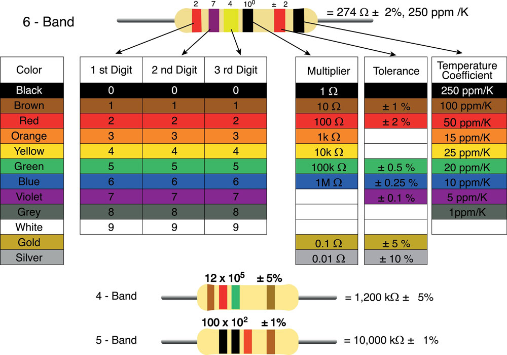
The meaning of the color coding used in resistors. Note the tolerance color coding.
- Replace the ideal values with the real values in the equations to see if they meet the required operating characteristics.
- Run these calculations using the values at extreme tolerances. The 150Ω resistor will not be as accurate as the 130Ω type because its 5% tolerance is 7.5Ω. So its range will be 142.5Ω to 157.5Ω. Remember to calculate the resistor power dissipation and circuit current draw.
Applications of Current Limiting Resistor
Current limiting resistors protect LEDs from permanent damage due to overcurrent and maintain constant brightness during use.
They are also important in protecting devices like batteries, motors, and audio amplifiers when charging and driving them, respectively.
A battery charging system for an EV.
Power supply systems and transistors require current limiting resistors, as well. Transistors use them to set the base current for switching.
Wrap up
In conclusion, current limiting resistors are essential for electronic circuits with diodes, like LEDs, due to their I-V curve. And you can calculate the resistor value using the formulas above depending on your LED arrangement. That's it for now. If you have any sentiments or questions, leave a comment, and we'll be in touch.
Special Offer: Get $100 off your order!
Email [email protected] to get started!