Blog  /  IC Board: Important Details to Know as a Circuit Designer

IC Board: Important Details to Know as a Circuit Designer

In the realm of modern electronics where integrated circuits (ICs) are foundational, understanding the assembly and manufacturing processes is vital. OurPCB excels in providing Printed Circuit Board Assembly (PCBA) services, which are essential for mounting and integrating ICs onto boards. This service ensures that all components are precisely placed and securely soldered, facilitating the creation of efficient and reliable electronic devices.
Quote Form
check whiteFastcheck whiteExciting Dealscheck whiteFree
1 2 3
Table of Contents

Modern-day technology and the circuit board IC are almost inseparable. ICs are majorly present in high-density computer-related chips that need to optimize space per component. They are present in virtually all modern electronic devices and systems.

So, as an end-user or circuit designer, it is essential to have an extensive idea of circuit board ICs. Reading on also enlightens you on the different types, how they work, the manufacturing processes, etc.


1. What is an IC Board?


An IC board is a printed circuit board assembly type that permits the mounting of integrated circuits. By default, it has points for you to solder components and wires onto its surface.


2. What is the Difference Between IC PCB and standard PCB?


IC PCB stands for integrated circuits, pointing to an integrated chipset or module. These IC PCBs are a crucial part of digital and analog circuits. A perfect example of one is a motherboard with a Northbridge chip.

So, in general, IC PCBs are complete electronic circuits integrated into a single chip. Once a part is damaged, it affects the entire course.


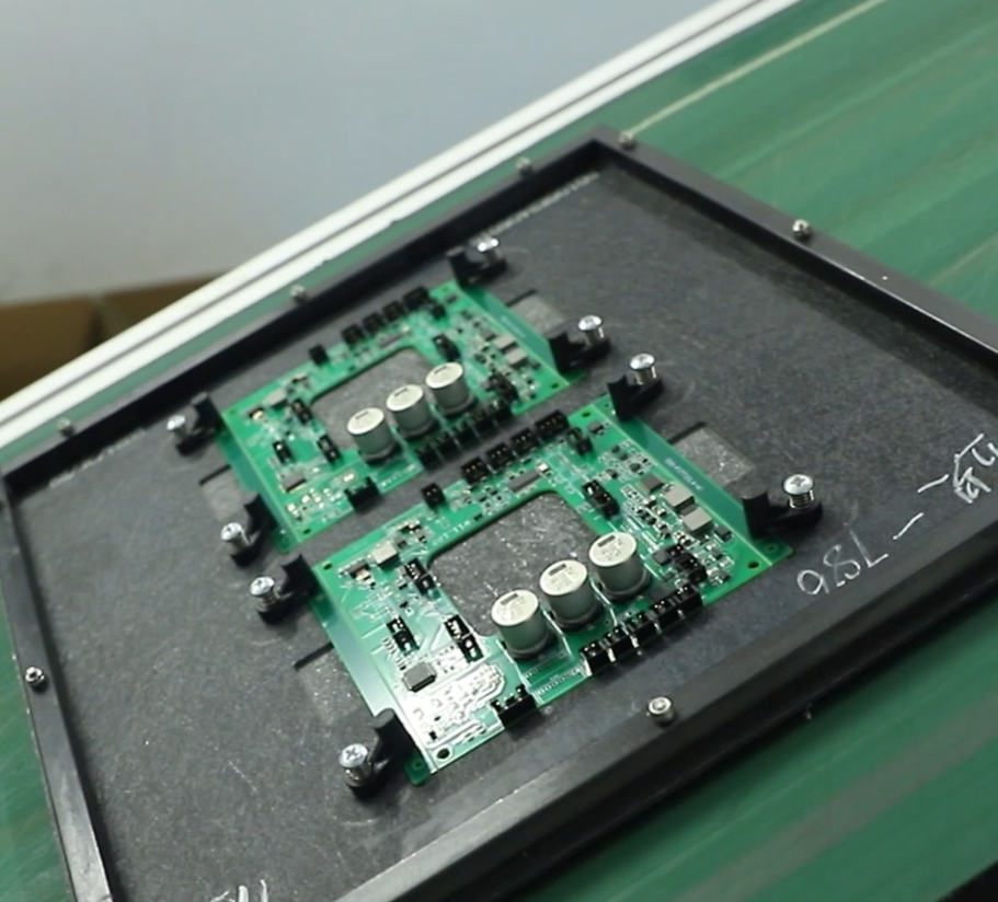
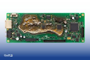
A batch of IC PCBs

(A batch of IC PCBs).


On the other hand, an ordinary PCB is a single piece of silicon panel with a few passive components. It is the base of most electronic circuit assemblies.


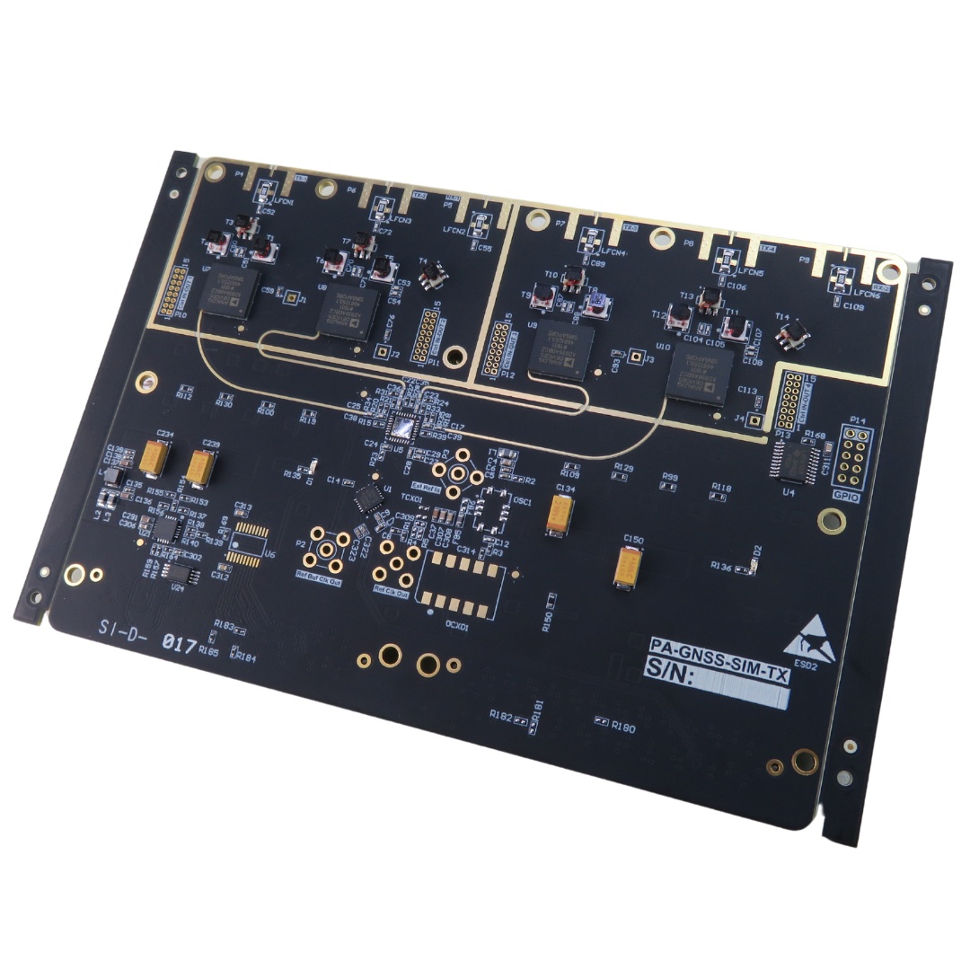
A plain PCB panel

(A plain PCB panel).


These silicon chips come in various types and sizes. Also, they follow copyright laws to suit general chip topographies. The copyright approach regulates the cost of licensing the silicon gate technology developed for the ICs.


3. How do IC boards work?


The IC boards function via the connections of the components. In most cases, their forms and sizes depending on the degree of integration meant for the board. The billion-transistor processor era uses ultra-large-scale integration with billions of components. It contrasts small-scale and medium-scale integration, where there are thousands of transistors.

Most use CMOS integrated circuit technology as base tech. However, one common property in all ICs is the interconnection of wires to link all the components.

Sometimes, mechanical assistance may be required to connect components to external devices. Therefore, some boards support a frame or structure for linking internal and external wires. In other cases, the IC boards support the electrical properties for keeping an electrical connection between components intact.


Common IC Formats

There are five typical IC formats, each with different characteristics to suit different applications. They include the following.

Logic Gates

Logic

gates come in different types, each performing a specific boolean operation. Chips with logic gates combine several to perform complex boolean logic operations on data. But the common factor between the inputs and outputs from these operations is they can either be logic highs or lows (1 or 0).

Vector symbols of the different logic gate types

Vector symbols of the different logic gate types

Some of the most common implementations of logic gates are flip flops and latches, which are used to make devices like shift registers because they can store state information.

A flip-flop logic circuit diagram and truth table

A flip-flop logic circuit diagram and truth table

Voltage Regulators

Voltage regulators are circuits that maintain a fixed or constant voltage output even as the input voltage level fluctuates. The circuit also maintains this fixed output voltage despite load changes.

Devices like generators and car alternators have voltage regulators with discrete components, but there are miniaturized chip-sized versions that fit on PCBs to form compact power supply regulators for board components.

The LM7805 voltage regulator IC on a PCB

The LM7805 voltage regulator IC on a PCB

Microcontrollers, Microprocessors, and FPGAs

Microcontrollers

house microprocessors, memory, interfaces, and all other peripherals in one chip. They can have more than one CPU, but these cores are usually not as powerful as microprocessors.

On the other hand, microprocessors host more powerful CPUs on a single chip, with the memory and other peripherals being external. Therefore, these chips have a higher power consumption and more complex development process than microcontrollers.

A microprocessor

A microprocessor

FPGAs

are rather unique because you can reprogram them after manufacturing. So, unlike microprocessors, they don’t have fixed instruction sets; you can reconfigure them to meet any use case or application. These ICs excel in parallel processing but consume more power than microcontrollers to achieve this performance.

Sensors

Sensors

molded into integrated circuits perform specific environmental condition detection tasks. They include devices like temperature sensors, accelerometers, and gyroscopes.

Timer ICs

These chips provide an output signal after a specific period to provide precise timing using duty cycles. They are the go-to ICs for timer, oscillation, delay, and pulse generation applications.


A 555-timer IC

A 555-timer IC


4. Types of IC Boards for Surface Mount


There are different types of IC boards for surface mount. But, the major SMD package types are five in number.

  • Small outline integrated circuit (SOIC)
  • Ball grid array (BGA).
  • Quad flat pack (QFP).
  • Small outline package (SOP)
  • Plastic leaded chip carrier (PLCC)

Furthermore, there are multiple styles for these SMD package IC types. For example, SOP packages have:

  • Shrink the small outline package (SSOP).
  • Thin shrink small outline package (TSSOP).
  • Light small outline package (TSOP).
  • Quarter-size small outline package (QSOP).
  • Tiny outline package (VSOP).

Also, in the quad flat package (QFP), the following are surface mount IC boards:

  • Ceramic quad flat pack (CQFP).
  • Low profile quad flat pack (LQFP).
  • Plastic quad flat pack (PQFP).
  • Thin quad flat pack (TQFP).

There are so many other options. Therefore, it is essential to choose the most suitable IC board for surface mount from a top electronics manufacturer.


5. Mechanisms of IC Boards


The mechanism of an IC board relies on a durable and stable device base for connecting a chip of semiconductor material. The IC boards help electronic engineers install various devices using one or more integrated circuits.

Most IC boards use one power supply to operate the linked devices. As a result, if there is a fault in the IC board connection, it affects all connected components.


Special Offer: Get $100 off your order!

Claim your $100 discount by sending an inquiry today. Act now to save on your next project!
Please email [email protected] for details.

6. Purpose of IC Boards


The purpose of IC boards is primarily for use in modern electronic appliances. Hence, they often come in smaller sizes fit for consumer products. This feature makes them a popular part of several different appliances.

Also, IC boards are helpful in industrial products. There are many IC boards specifically designed to handle high-end industrial functions.


7. Applications of the circuit board IC


The circuit board IC has vast applications. They are:

Automation


Circuit boards, in general, aid the automation of processes for manufacturers and end users. Some of the automation applications of a circuit board are robots, packaging lines, printing machines, timers, etc.


Industrial control


As mentioned above, it is crucial in industrial processes. Therefore industrial robots, automated control systems (ACS), forklifts, and factory automation benefit from microcontroller circuit ICs.


Medical


Medical equipment also benefits significantly from the application of circuit boards. You find them in medical equipment like Endoscopes, blood pressure machines, X-Ray machines, etc.


Mechanical


IC boards are also popular in mechanical and assembly line equipment. These include conveyors, robotic arms, pick and place units, etc.


Vacuum


They are regular components in specialized machines such as servicing and maintaining vacuum systems. These vacuum systems are applications useful in food processing factories and warehouses.


Test


Likewise, they are helpful in instrumentation, test chambers, measurement devices, etc.


Miscellaneous Electrical


In general, many electrical devices depend on ICs for their operation. Lights, fans, and remote controls require a circuit board to control the applied electrical signals.


8. Common IC parts


Ceramic:


These are the ceramic parts of an IC package. Most small and medium-sized devices of about 5mm use them.


Thin Miniature Metal-Can:


These integrated circuit parts use smooth solder masks or wire leads to attach different ICs. They are popular in size-tight designs like voltage regulators, microprocessor chips, oscillators, amplifiers, and DC-DC converters.


SMD:


It is otherwise called a Small Surface Mount Device. It is an essential part of memory circuits and logic gates.


Through-hole:


The through-hole is typical in larger circuit design applications. You find them in power supply outlets, MOSFET logic gates, calculator chips, Op-Amp chips, device chassis, etc.


BGA (Ball Grid Array)


This IC component is essential in digital circuits of high performance and reliability. Televisions, digital computers, and high-end electronics are some of these applications. BGAs are often between 25mm to 500mm in size.


A BGA semiconductor IC

(A BGA semiconductor IC).


Flip Chip:


These are small electronic components, usually about 5mm in size. They are essential in digital circuits, analog circuit converters, microcontrollers, logic gates, microprocessor chips, memory circuits, and more.


QFP (Quad Flat Pack):


Like BGA, complex electronic devices use QFP. Examples include smartphones, digital computers, digital TVs, etc.


CSP (Ceramic Small Package):


Likewise, these components form parts of complex devices with HDI requirements. For example, a typical cell phone integrates many different elements in a tight circuit board space.


The Benefits of Installing ICs on PCBs

Miniaturization

Integrated circuits house the combined performance of multiple components into one tiny chip. This design loops these components and optimizes their performance to make the PCB more powerful while having a compact footprint.

Simplified Design

Incorporating ICs into PCBs simplifies the electronic component’s design because the devices handle complex tasks. So you don’t have to worry about implementing tasks like timing, sensing, and voltage regulation. Simply include the chip in your circuit design, then solder it later.

An integrated circuit soldered to a PCB

An integrated circuit soldered to a PCB

Affordability

Integrated circuits house and loop multiple electronic components into one device. This structural integration is cheaper than having to include the parts separately on the board. The integrated components consume less power than discrete components, meaning the board will be more efficient.

Expands the Application Scope

The high processing power, miniaturization, and efficiency provided by ICs make PCBs with these components ideal for multiple complex applications in military devices, industrial equipment, advanced consumer electronics, and telecommunication equipment.

Additionally, chips have a lower failure rate than discrete components, making these boards even better for these applications because they must have a high-reliability factor.


9. IC Boards Installation Process


Before you begin an IC board installation, you must follow these design rules carefully.

  • First, you must prepare the right tools for the assembly process. One essential tool here is the soldering iron. The temperature should be between 220 and 270 degrees Celsius—excessive heating results in insulation breakdowns, thermal shocks, and eventual IC material damage.
  • Do not scratch the component leads. Using metal tweezers, for instance, causes damage to the authorities and may break off.
  • Avoid touching the IC pins with static electricity inducers like a hairdryer.
  • Also, avoid unnecessary contact with the surface of the IC. Excess solder and flux, for example, cause damage to the board.
  • Always keep the IC from exposure to twisting, bending, moisture, and excessive heat conditions.
  • Lastly, completing the coupling requires a test run on the IC. This measure ensures the circuits or devices are working as intended.


10. Types of Damage to Common ICS


Although damage to circuits is of different variants, there are two main types of damage to ICs. They are electrical damage and physical damage. Others come from inappropriate handling, wrong application, etc.


Electrical Damage


Electrical damage of ICs mainly affects the solder bonds at the leads and PCB pads. Short circuits are a result of bent information contacting the other pads.


Electrical damage caused by short circuit

(Electrical damage caused by short circuit).


Physical Damage


Physical damage often includes flex defects on the piece of the silicon circuit board. These defects happen when the little metal pins that connect the board to IC get broken or bent.

It is, therefore, crucial to apply extreme care when handling integrated circuit boards. By default, they are very delicate, sensitive to mechanical influences, and damage easily.

Not limited to mechanical shock, ICs are also sensitive to chemicals. Certain solvents dissolve the electrical properties of the PCB materials used. Therefore, limit any exposure to chemical-heavy environments.

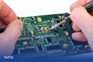
Also, apply utmost care during circuit board installations. After applying flux to the IC leads and pads, press it down onto the circuit board pads with your thumb or index finger.

Other ICs with ceramic and polysilicon packages are too fragile to heat up quickly. They also break down on the least stress.


11. IC board Manufacturing Process


These are the design rules chip designers need to know.

Choose the best design for your IC board.

The first step to producing your own IC board is the choice of a suitable design. Therefore, considering all the relevant details before you begin is essential. These considerations include:

  • Component and material types.
  • Amount of features required for the design.
  • The spacing requirement for the PCB assembly.


Select a good PCB manufacturing company


Choosing the proper chip manufacturer is the next important step. The job of the chip designer is to tailor the design according to the current model.

So, to choose the ideal manufacturing company for your project ICs, here are a few things to consider.

  • The manufacturing processes of the company
  • The company's commercial circuit packaging
  • Assembly cost of products and services


Selecting a design to manufacture


When choosing a PCB design, the process of fabrication must be attainable. Otherwise, they create problems and eventual product failure after production. Again, this factor depends on the manufacturer to choose the right manufacturing processes for the circuit board.


Selecting component suppliers


In addition to commercial circuit packaging, some PCB manufacturers supply circuit board components. This circuit design step ensures that the components meet the degree of integration. In any case, the electronic engineer needs to choose a reliable component supplier.


Establishing an assembly process


Afterward, the assembly process of the PCB components follows. This assembly helps to test the functionality of the finished product.


Final step


The final step involves carefully rechecking all factors related to the component's design in line with its functions. At this point, the engineer confirms the average accuracy and error rates.


12. How to choose a Proper Circuit Board IC?


The primary aim of a circuit board is to connect components in a single power supply unit. So here is how to choose the ideal circuit board ICs for you.

  1. First of all, you must choose a good design that serves the purpose of your circuit board IC. These include the cost of materials needed, component sizes, and how easy it is to fabricate them.
  2. Also, ensure you know how your chosen PCB design works and the features therein.
  3. Again, make sure the manufacturing processes follow the correct standards.

In all, the PCB engineer ought to know these procedures well. So, when he implements these special design techniques, it functions correctly.


Conclusion


Circuit Board ICs are the chassis of most electronic devices. They house billions of components in a very large-scale integration.

It requires expert handling in production and usage. Few places have all the resources you need to become a top circuit designer. Talk to the team at Ourpcb for your circuit board ICs, production, assembly, and supply.


Special Offer: Get $100 off your order!

Claim your $100 discount by sending an inquiry today. Act now to save on your next project!
Please email [email protected] for details.

Related Post