Most of us are used to white light, which is familiar with conventional incandescent lamps. But if you have visited a movie theatre, you might have noticed they use a different kind of light. That light is synonymous with the burst of light useful when taking photographs, much like the precision required by printed circuit board manufacturers in creating components that operate under specific lighting conditions.
Noble gases are responsible for the production of such light. Hence, in that regard, we will look at the basic concept of an inert gases type of circuitry. Check out this article for the working principle of the xenon flash tube circuit.
Contents
What is a Xenon Flash Tube Circuit?

Xenon Car Headlights
A xenon flash tube primarily comprises a glass tube filled with an inert gas. It is similar in operation to a neon lamp circuit. We'll explain its working principle in the sections below.
Special Offer: Get $100 off your order!
Email sales@ourpcb.net to get started!
How Does a Xenon Flash tube Circuit Work?

Modern Car Xenon Lamp Taillight
The primary working principle of this circuit is the same as for all fluorescent tubes. When electric current passes through the gas encompassed in a box, it creates an invisible ultraviolet light. The light appears as visible light when it hits the sides of the glass tubing.
Similarly, a xenon flash tube circuit comprises a xenon tube containing xenon gas. The pressure inside xenon flash lamps can be high or low, depending on the type. On the extreme ends of the line, there are electrodes connected to a high voltage power source.
The disintegration is via the process of ionization. When you turn on the input voltage, gas particles will become activated, splitting into tiny bits. Thus, activated ions will be created by this process. Consequently, the ions will collide with neutral atoms and electrons in the tube, leading to the production of flash energy.
The collision process will lead to electric discharge. Hence, we can refer to xenon flash tubes, argon tubes, and other lamps made using noble gases as discharge lamps. Also, a mercury lamp operates in the same manner.
How to Build a Xenon Flash Tube Circuit?
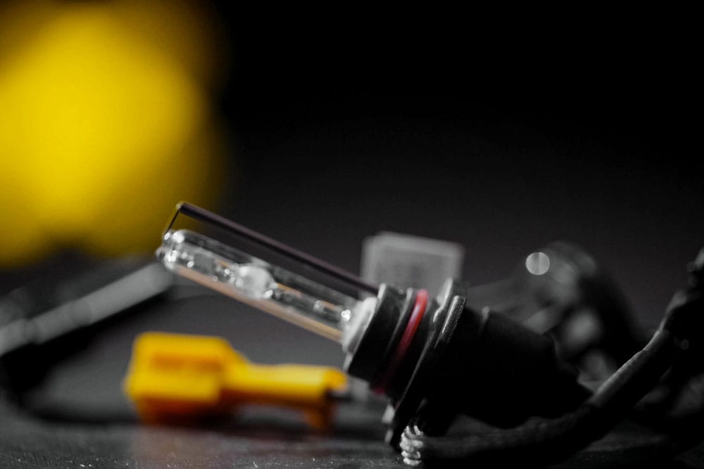
Xenon lamp on the table
There are different types of xenon flash tube circuits. We will look at the three main ones that you can quickly assemble.
Simple Xenon Flash circuit
Using the circuit diagram below, you can create one of the most straightforward xenon lamps. Among the critical components of the electrical circuit is an AC input voltage and Silicon controlled rectifier (SCR).
Here is the circuit diagram:
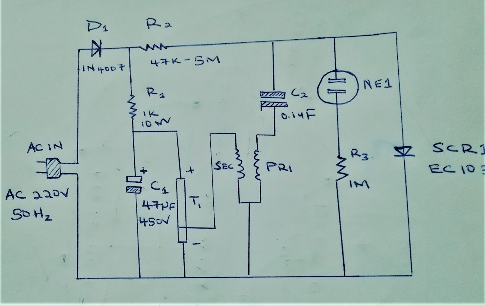
A Xenon Flash Tube Circuit
Circuit Explanation
First, the AC electrical current passes through a diode to rectify the AC to DC. Next, the DC passes to resistor R1 and capacitor C1, becoming an electrical charge. Simultaneously, current flows through resistor R2 to produce an electrical account on C2.
Subsequently, the current flows via T1, which is a pulse transformer. As capacitor C2 charges, its voltage power supply will significantly rise. The rise in voltage prompts the neon lamp to conduct when it attains a threshold voltage of approximately 90V.
Another significant component of this circuit is the trigger coil transformer. It is small in build but can increase the primary voltage at the primary winding. Thus, it's a step-up transformer.
The primary windings are significant in electromagnetic field induction on the secondary windings of the transformer. Consequently, the transformer produces numerous high voltage pulses that activate the xenon flash tube.
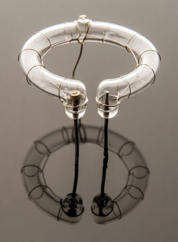
Flash tube
Components
Among the parts that are important for this circuit include:
- A 1N4007,1A 1000V Diode
- An EC103D Silicon controlled rectifier
- One xenon flash tube
- A neon lamp
- 1K 10W resistor
- 47K to 5 M resistor
- A pulse transformer
- 33uF electrolytic capacitor
- 630V mylar capacitor
- A PCB board and wires.
Xenon Strobe Light Circuit
The second circuit features a Zener diode. The replacement is better than a neon lamp as it facilitates more precise voltage checking.
Additionally, it has a more extensive lifespan than the average neon lamp. Also note, you can modify this circuit's flash duration and speed by altering resistor R2. Here is the circuit diagram:
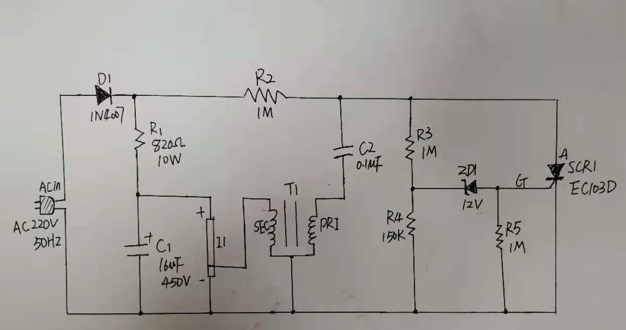
Xenon Strobe Light Circuit
Component List
- Three 1M resistors
- One 150K resistor
- An 820 ohms 10W resistor
- 0.1uF 100V mylar capacitor
- 16uF 450V electrolytic capacitor
- EC103D Silicon controlled rectifier
- 12V 0.5W Zener Diode
- 1N4004 Diode
- Xenon flash tube
- A Pulse transformer
12 V xenon flasher circuit
The circuit diagram below illustrates how to create a 12V xenon flasher circuit. You require a 12V DC power supply to operate it. Note, you can vary the flash rate of the system via an onboard potentiometer.
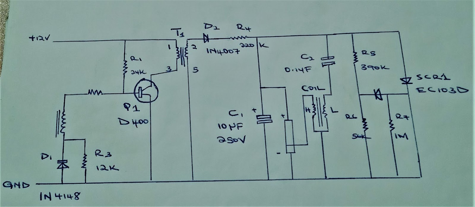
A 12 V xenon flasher circuit
It features three main parts: an oscillator, an RC network, and the flash circuit. You can use a car battery to power it requires a 12V DC power supply.
Applications

A car xenon headlamp
- In scientific applications for the illustration of an output spectrum and other spectroscopic uses
- In lighting applications
- The circuit is functional when taking a flash photo
- Useful as optical sources for particular types of lasers
- Essential in specific medical procedures such as sterilizing surgical tools
- In ultraviolet light curing applications
- Production of strobe lights for stroboscopes
- In generating ozone
Summary
Fluorescent lamps are not as standard as incandescent bulbs. Thus, you might not have been too concerned with their operating principle before. But in this article, we have shed light on the working mechanism of various kinds of xenon lamps.
Hence, you are now aware of how the commonly useful light for photographic purposes is produced. For further info on the production and operation of a strobe light, reach out to our experts.
Special Offer: Get $100 off your order!
Email sales@ourpcb.net to get started!