We are all familiar with the term USB. However, most people associate it with the connector. The connector creates the interface, but the USB PCB is the system's core because it aids in efficient data transmission.If you want to build a serial interface device with USB connectivity, there are some vital factors to consider. We have covered the board's design, connector types, issues, and design suggestions to consider. Read on to learn more!
Contents
- What is a USB PCB Board?
- USB PCB Design Components
- Shielding
- Strong Power Connections
- Polarization
- Strain Relief
- Four Contacts
- USB PCB Connector Types
- The Vertical Through Hole Connectors
- Top Mount Connectors
- Mid Mount Connectors
- Base Mounted Connectors
- Micro USB PCB Connectors
- USB-C PCB
- Common Problems of USB PCB
- Faulty USB PCB Ports
- Software Configuration Problems of USB PCB
- Hardware Problems
- Wrong USB Cable Extension
- Previously Connected Parts
- Suggestions for USB PCB Layout Design
- Summary
What is a USB PCB Board?
A USB circuit board is the heart of any USB serial interface device. These devices are popular and widely used because of their convenient interface, quick data transmission, and hot-swapping support. The USB PCB, being the device's core, is the primary component that enables such performance.
USB PCB Design Components
Shielding
Shielding protects and preserves the electrical signals running through the USB PCB if placed in an environment with high electrical noise. This function requires a metal covering that is not part of the circuit.
Strong Power Connections
This power connection design places power pins on the USB connector. It allows power connectivity before data connectivity and prevents device-powering above the data lines, which could be dangerous.
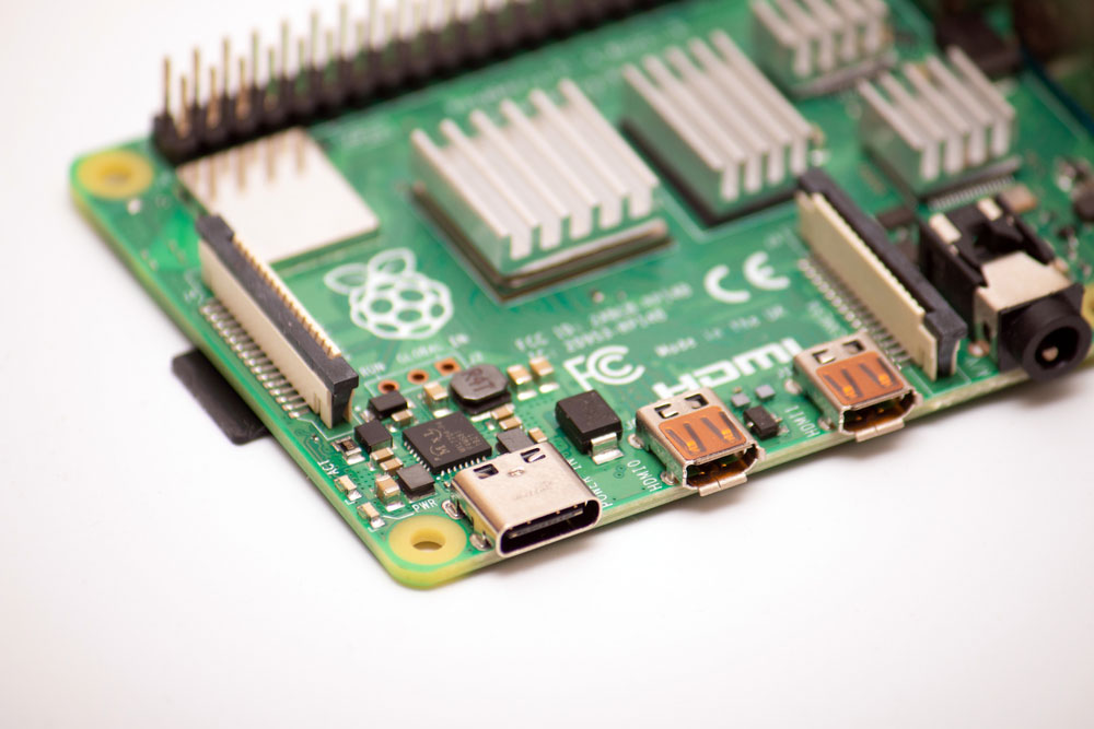
24-pin USB connector system with a rotationally symmetrical connector on Powered single-board
Polarization
Any USB connector has one orientation, so you can only connect it in one direction. Forcing a connection the other way will damage the device.
Strain Relief
A plastic coating provides strain relief to minimize the tension placed on the connector. The coating also eliminates stress on the cord, which might otherwise damage the USB device.
Four Contacts
All USB PCB connectors come with at least four contacts. USB 3.0 can have five or more, and you can spot these over the outer plastic bar. The four basic contacts include two data lines (D+ & D-), ground, and power. These connectors can convey 5V and 500mA maximum.
Special Offer: Get $100 off your order!
Email [email protected] to get started!
USB PCB Connector Types
USB PCB connectors are available in the following types.
The Vertical Through Hole Connectors
As the name suggests, this USB connector has an upright orientation. It is a female USB type containing staged plastic connectors in three, two, and four rows with a contact spacing of 0.05. The connector terminations go through coated/plated through holes on the circuit board before fixing. This design creates a slim track that is ideal for space-restricted applications.
Top Mount Connectors
Top Mount connectors are connecting strips knotted to a PCB's top-tier layer using break-off lead. It is suitable for mechanical devices because it can handle vibrations and falling objects.
Mid Mount Connectors
Mid-mount connectors sit at the midsection of a PCB, and you can mount them using through-hole or surface mount methods. They are ideal for low-profile electronics and come in handy if the PCB has height limitations below and above.
Base Mounted Connectors
These connectors attach to the PCB's underside primarily using surface mount technology. They can join two circuit boards using links between applications passing across the board.
Micro USB PCB Connectors
Micro USB PCB connectors are smaller USB intersection designs invented to connect mobile devices. They feature a tinier port than most USB connector sizes.
However, they are superior to most mini USB interfaces. Additionally, their design boosts USB OTG performance while allowing mobile affinity. On top of that, the technology enables compact mobile devices to communicate directly without needing a host computer. Incorporating micro USB connectors into PCB designs requires understanding microSD pinouts for seamless data transfer and reliable performance, all while supporting compact, mobile-friendly functionality.
Of course, you need a micro USB cable to link the connector to the PCB. It is the smallest USB cable type and has two connection methods plus USB 3.0. Despite this size, the cable's performance matches that of all-purpose USB cables.
USB-C PCB
USB connectors have undergone several upgrades, and these improvements usually come with changes in shape. USB-C has, so far, gained the most acceptance among most electronic devices because of the following advantages.
- Reversible/overturning capability
- Delivers power and transmits data simultaneously
- Quick data transmission speeds
- Thin profile
- Durable than micro USB-B type connector
- Higher voltage and current carrying capacity
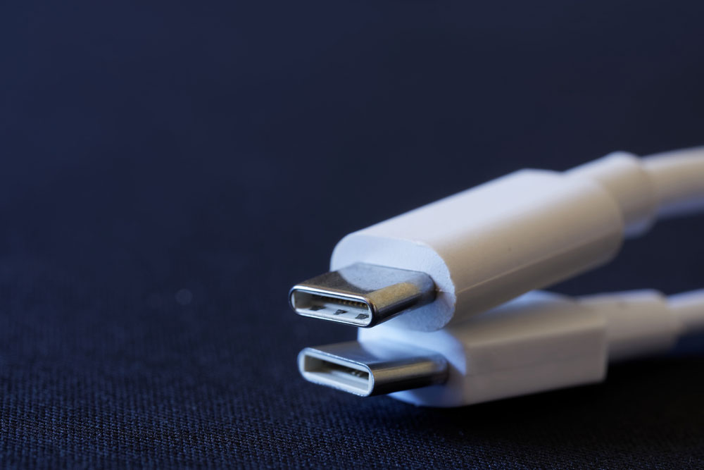
Two USB Type-C connectors
Common Problems of USB PCB
Faulty USB PCB Ports
A defective USB port can cause malfunctions or errors in a USB PCB. But it could be the port or device, so you should determine where the problem is first. Plug in the device to another USB port. If it works, then the previous USB port is faulty. If not, the device is not working. You can solve this issue by trying the following.
- Check and clean any accumulated dirt in the USB port
- Physically check if the port is broken or loose
- Uninstall the USB host controller (check the device manager)
- Restart your computer
- Replace the USB port
Software Configuration Problems of USB PCB
Invalid operating systems or software can cause USB PCBs to malfunction. This problem can occur after installing a new operating system or altering the computer settings. You can solve this issue by:
- Ensuring you have the correct and updated drivers
- Check the device manager, main setup, or control panel settings
- Do a virus scan to check the computer's health
Hardware Problems
Hardware problems could be looseness on the expansion slots, slot failures, loose/detached wires, damaged ports/controllers, etc. If you encounter this problem, try these solutions.
- Inspect connectors/ports for dirt and dust
- Run a physical check to see if any parts or wires are loose
- Replace all the faulty hardware
Wrong USB Cable Extension
Using the wrong USB extension cable, such as a low-speed cable to connect to a high-speed device, can cause malfunctioning. You can solve this using the following solutions.
- Pick the correct USB extension cable.
- Check the USB type (A, B, or C), then pick the ideal cable
- Read the device's user manual to check the suitable extension cable types
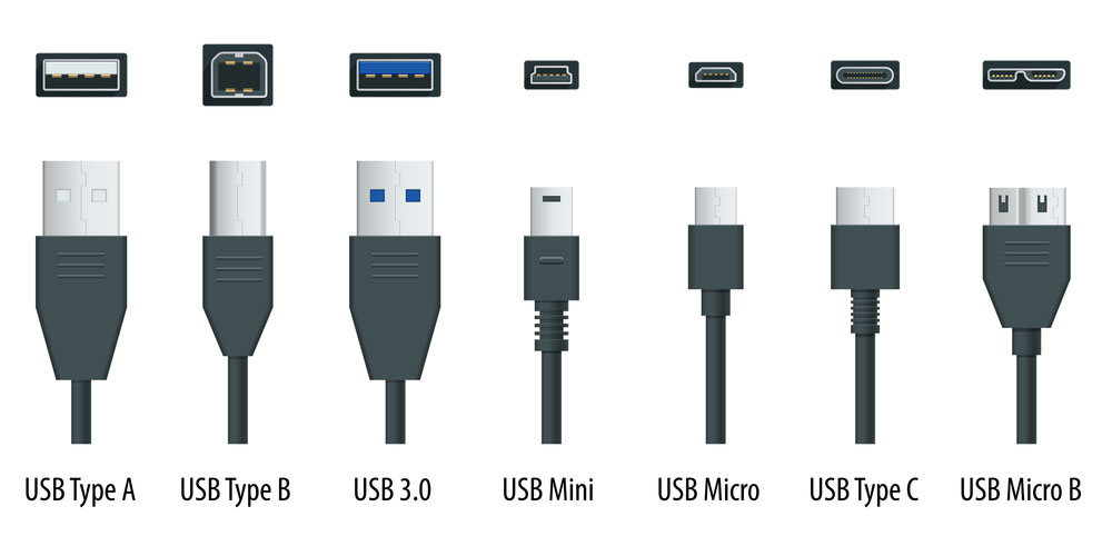
USB types ports and connectors.
Previously Connected Parts
Your USB PCB might not function if you had connected a faulty device earlier. Also, rapid connection and disconnection can make the ports malfunction. You can solve this issue by:
- Restarting the computer
- Resetting the USB controller
- Disconnecting then reconnecting the USB device and scanning for hardware changes
Suggestions for USB PCB Layout Design
- Make the differential signal line as short as possible when positioning the components.
- Draw the differential lines first and don't exceed two via pairs on a differential line pair.
- Apply symmetrical parallel routing to couple two wires tightly.
- Space the ground and signal networks from the differential lines by at least 20 mils to minimize crosstalk.
- Consider the pull-up resistor placement, differential series connection resistance, and test point.
- Matching the differential line length is challenging due to pin distribution, trace space, etc. Therefore, you should implement a differential pair mismatch compensation to match the line length. Keep in mind that you can control the length difference within five miles.
- Keep a close eye on the GND and VBUS line widths because the USB's output current should be 500mA.
Summary
In conclusion, USB PCBs play a significant role in modern-day computers. However, USB technology is advancing rapidly, and it would make more sense to implement USB-C in your project. However, ensure you stick to the design components and implement the layout design suggestions when setting up. If you come across any issues, feel free to contact us for more details.
Special Offer: Get $100 off your order!
Email [email protected] to get started!