Contents
- MicroSD Pin Configuration
- MicroSD Pinout: Types of Micro SD cards
- MicroSD Pinout: Advantages and Disadvantages
- Advantages
- Disadvantages
- How to choose MicroSD Cards?
- Interfacing Micro SD card Module with Arduino
- Getting the Micro Secure Digital card ready.
- Linking the Micro SD Card Module with Arduino
- Arduino Code
- MicroSD Pinout: How to design the Micro SD Circuitry
- Example 1
- MicroSD Pinout: Example 2
- MicroSD Pinout: Applications
- Summary
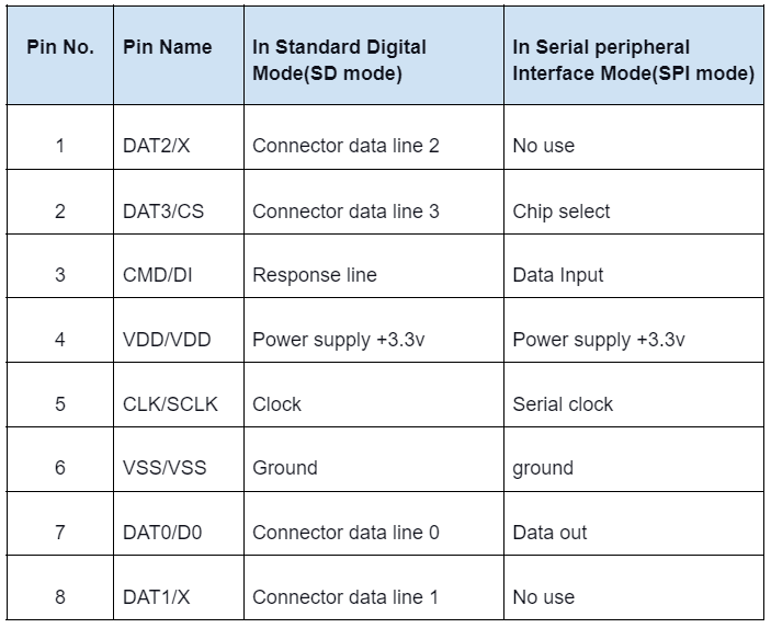
MicroSD Pin Configuration
The table below represents the pin configuration for a Micro Secure Digital PCB prototype service.
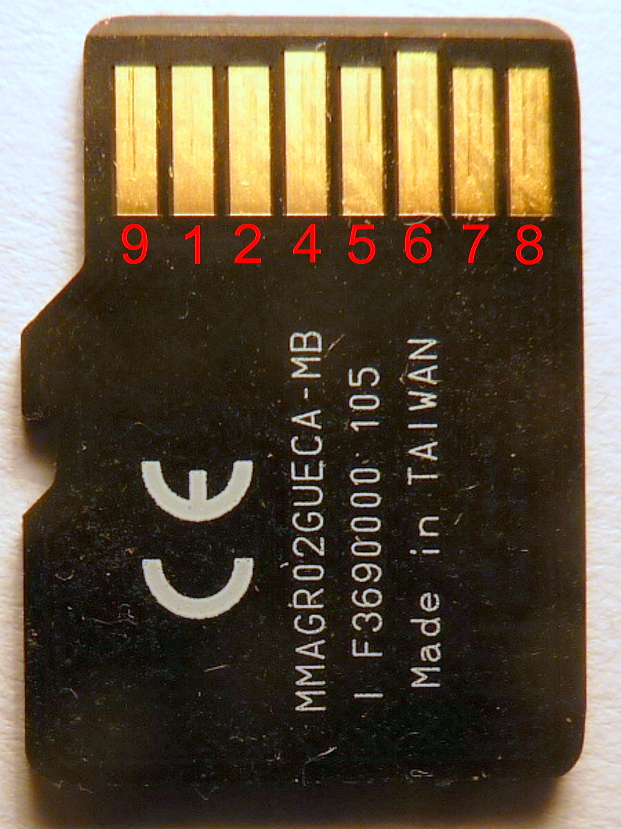
A micro SD card pinout
Source: Wikimedia Commons
Micro SD card features and specifications
- Storage capacity:4GB,8GB,16GB,32GB,64GB, etc.
- Form factor:11×11×15 all in millimeters
- Speed class: class 2- class 10
- Operating Voltage:2.7V- 3.3V
- Transfer speed: Averagely 95 MBs per second
- Storage system: FAT12, FAT16
- File system: SDHC/SD/SDXC
MicroSD Pinout: Types of Micro SD cards
There are three types of Micro SD cards, all having an almost similar physical interface but different memory sizes, namely:
- MicroSDHC card(Secure digital high capacity)
- MicroSDXC card(Secure Digital Extended Capacity)
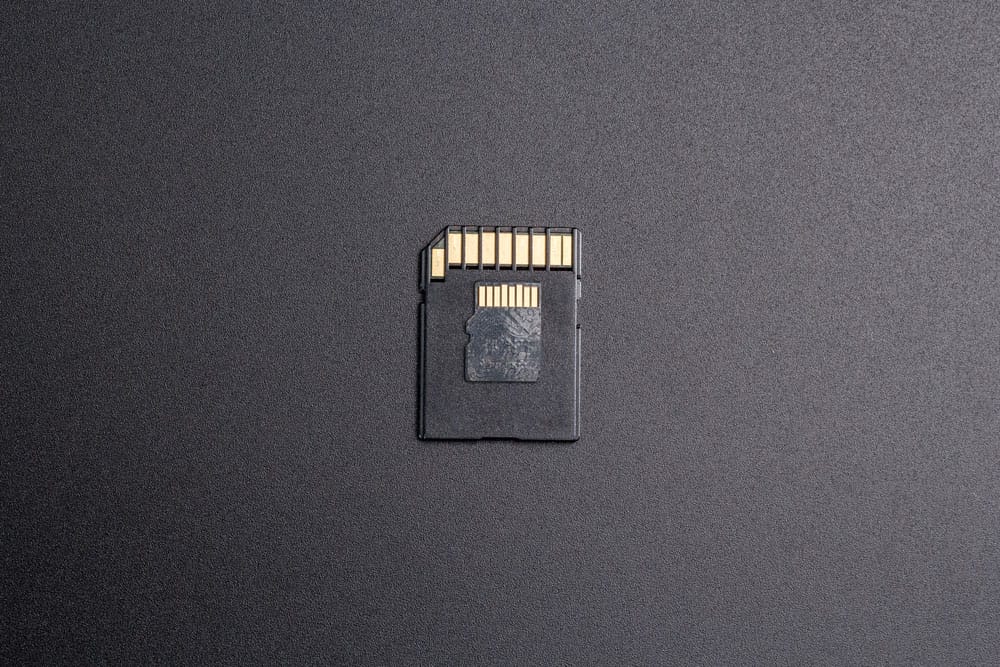
A MicroSDXC card
- MicroSD card (Standard Digital)
MicroSD Pinout: Advantages and Disadvantages
Advantages
- Easy to access on personal computers
- Portable & removable
- Lowers phone consumption memory
- Utilizes less power.
- You can increase the storage
- Non-Volatile Memory
Disadvantages
- Limited write and rewrite cycles
- Slower than primary memory
- Apps may disappear when you remove the card
- Low-quality memory cards may impair a phone's performance
- Prone to physical damage
When working with MicroSD cards, it’s essential to understand their role in broader circuit designs, including how they interface with other PCB components like connectors and controllers. This ensures better performance and reliability in your electronic projects.
Special Offer: Get $100 off your order!
Email sales@ourpcb.net to get started!
How to choose MicroSD Cards?
As earlier stated, various types of memory cards are currently present in the market.
Thus for you to choose a suitable Micro SD card, you need to consider factors:
- Card size or Memory size
- Speed of the Micro SD card is mainly affected by the cards clock signal
- Compatibility with your device
- The intended purpose of the card
In addition, always check whether your device has a designated card slot since not all devices have card slots. 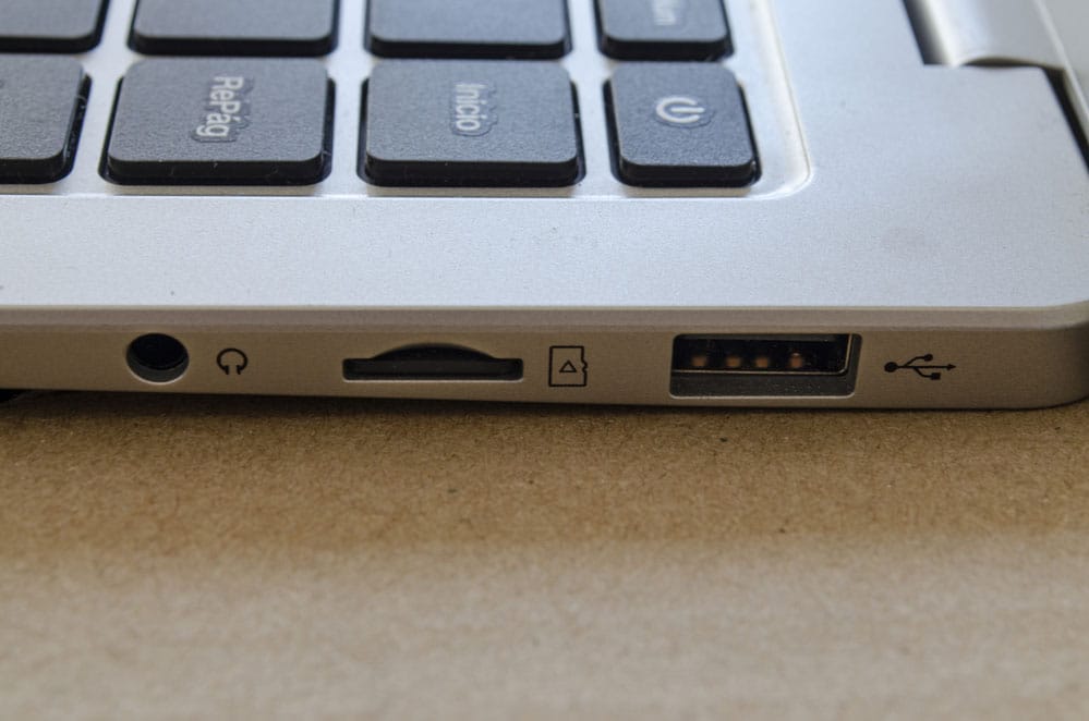
Memory card slot and USB slot
Interfacing Micro SD card Module with Arduino
Getting the Micro Secure Digital card ready.
Before placing the Micro SD card inside the module and connecting it with the Arduino, you first need to format it.
Generally, depending on the Arduino IDE library you will be using, you need to format the MicroSD card to either FAT32 or FAT16.
Note that FAT 16 or FAT 32 will work better on cards made for consumer devices than industrial devices.
If your Micro SD card is new, then chances are card manufacturers are already formatted according to the FAT system.
However, how the card manufacturers formatted the Micro SD card may lead to issues in your project.
In addition, if you are using an old card, you will also have to format it. To sum it up, whether you are using a new or old Micro SD card, it is always advisable to format it.
For effective formatting, card manufacturers recommend using the SD Associations SD Card formatter since it clears many issues that may arise from wrong formatting.
Download and install the formatter, select the required drive, then tap FORMAT.
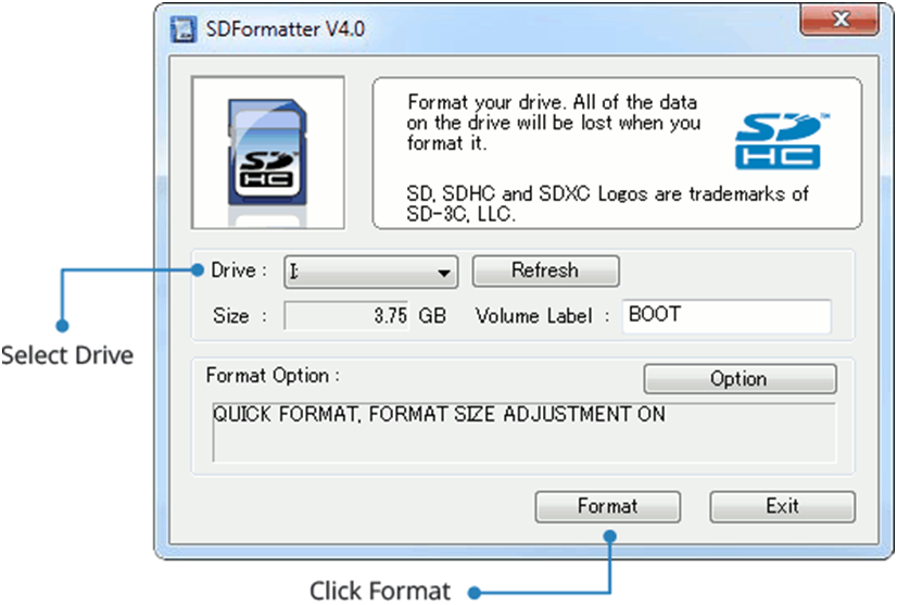
How to format your MicroSD using the SD Formatter.
Linking the Micro SD Card Module with Arduino
Once you have successfully prepared your MicroSD card, you may wire the breakout board.
Firstly place the microSD card module inside the protoboard. Then Link the module VCC pin to the Arduinos 5V and the GND pin to Arduinos GND. After which, you will have pins needed in SPI communication.
Since MicroSD cards need substantial data transfer, they will work well when attached to a microcontroller's hardware SPI pins. The reason is hardware SPI pins are faster hence more effective.
To prevent connection mistakes, check the pinout of the Arduino Pro Micro or the board you're using because SPI pin layouts can be different for each model.
Arduino
For example, Uno and Nano Arduino boards have SPI pins: digital 13(SCK), 12(MISO),11(MOSI). In addition, you will require a fourth pin for the SS line(Slave select), mostly pin 10. However, any pin will work just fine.
Below is a table you can follow for proper Micro SD card module and Arduino pin connection.
| Pin Number | MicroSD Card Module Pinout | Description | Arduino Connection |
|---|---|---|---|
| 1 | VCC | Power supply (usually +3.3V or +5V) | 5V |
| 2 | GND | Ground connection | Ground |
| 3 | CS (Chip Select) | Active low signal to select the SD card | Digital pin 10 |
| 4 | MOSI (Master Out Slave In) / COPI (Controller Out Peripheral In) | Data input from the microcontroller to the SD card | Digital pin 11 |
| 5 | MISO (Master In Slave Out) / CIPO (Controller In Peripheral Out) | Data output from the SD card to the microcontroller | Digital pin 12 |
| 6 | SCK (Serial Clock) | Clock signal from the microcontroller to the SD card | Digital pin 13 |
| 7 | CD (Card Detect) | Optional pin to detect if the card is inserted | Digital Pin 9 |
| 8 | WP (Write Protect) | Optional pin to enable write protection on the SD card | Digital Pin 8 |
In the rare chance that you have a Mega Arduino, then you will employ digital pins 50(MISO), 51(MOSI), 52(SCK), and finally 53(SS).
The table below indicates the various digital pins of Arduino Boards.
| Arduino Board | MOSI | MISO | SCK | SS |
|---|---|---|---|---|
| Arduino Nano | 11 | 12 | 13 | 10 |
| Arduino Uno | 11 | 12 | 13 | 10 |
| Arduino Mega | 51 | 50 | 52 | 53 |
Arduino Code
Now that you have linked the microSD card Module to the Arduino IDE, you can upload the code.
You can find the program in the Arduino IDEs library navigate to File, for example, SD then Card info. Once you tap on the card info, the program will open in a current window.
After that, you will have to change the number on the chip select to 10. We use ten, assuming you use either Arduino Uno or Arduino nano. Otherwise, you can change it to any pin you will use.
Then collate and upload the code. You should see the Micro SD card module information printed if you did everything correctly.
It is worth noting that SD cards have default speeds of 12.5Mbps when reading and writing.
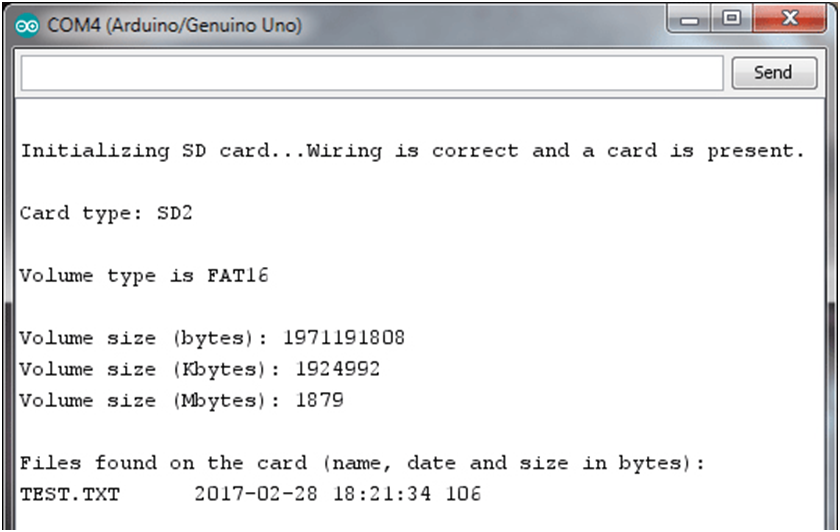
Printed Micro SD card Information
After uploading the code and nothing appears, then it means you wired the project wrongly. So retrace your steps to check for any faulty connections.
If you fail to find a faulty connection but the Micro SD card you used was faulty, then you may see a message stating initialization failed with a couple of troubleshooting tips.
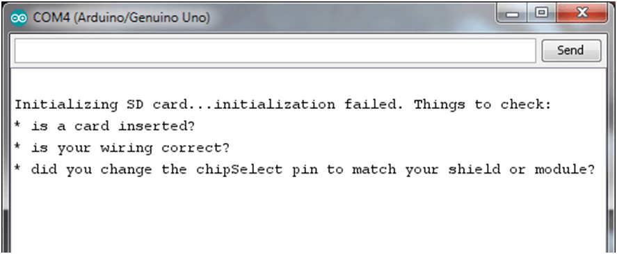
Initialization failed message with troubleshooting tips.
If you did the wiring correctly and formatted the card to either FAT 32 or FAT16, then the program will work efficiently, printing card details and files present.
If you incorrectly formatted the card or used a locked card, a message will appear below.
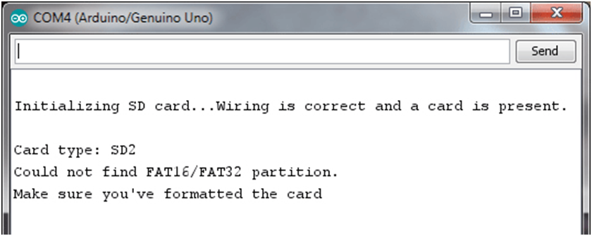
A message indicating correct wiring but wrong formatting
After successfully initializing your Micro SD card, you can apply the code below to write and read data from the SD card files.
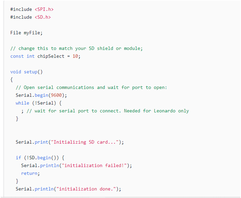
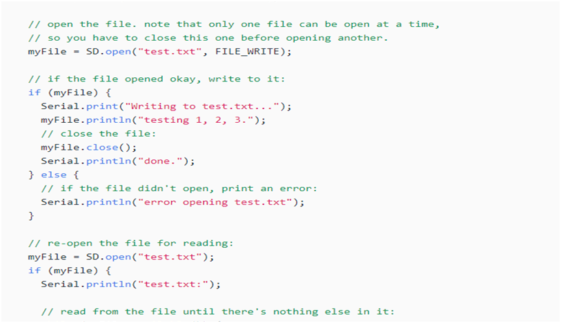
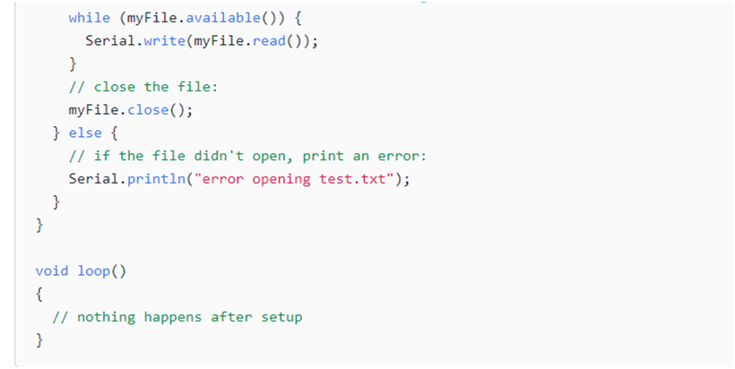
Arduino code
The code is rather easy to understand; first, it establishes a serial transmission link at 9600 bauds once the microcontroller goes on.
The card initialization happens when you type either I or me on the serial monitor. Consequently, the code will print whether or not the initialization was successful.
MicroSD Pinout: How to design the Micro SD Circuitry
A circuit's design makes or breaks the performance of a project. Therefore below are sample circuit designs you can follow to design a Micro SD circuitry.
Example 1
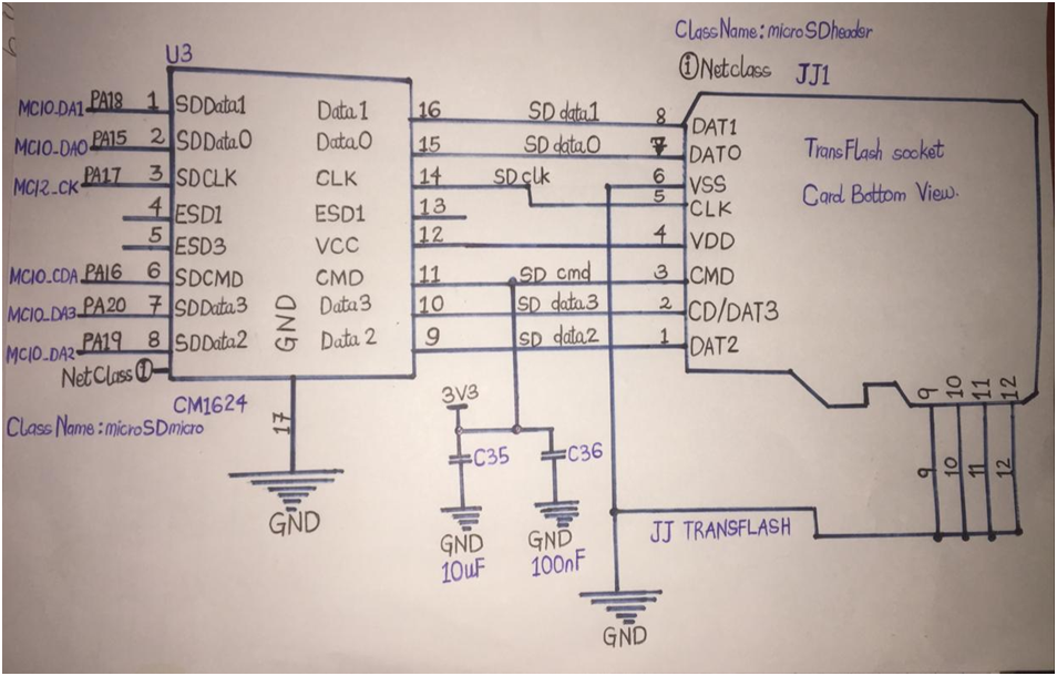
Circuit diagram showing a 4-bit transfer mode attachment from SDMMC outskirts and the SD card.
Where;
The standard Disk is susceptible to the environment; it may incur damage from electrostatic charges, gotten from our bodies and released when we touch it.
To protect the circuit, use EMI filters and TVS diodes to filter radiated and conducted emissions and meet EMC standards. During PCB production, place these components accurately to ensure the circuit meets performance and safety requirements.
MicroSD Pinout: Example 2
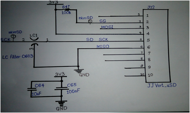
Circuit showing SD card used in SPI mode
The chip pick signals, MOSI, clock, and MISO interlink following the SDA specifications from the above diagram. In addition, the SD card functions in SPI mode.
MicroSD Pinout: Points to note
Whether using the SD card in SPI or 4-bit mode, the tracks quickly transfer the clock and data signals.
Therefore, to avoid snags, you need to;
Seriously examine propagation time to ascertain the data is stable before activating reading and writing by the clock.
Keep the tracks below and around the fine ground plane to prevent crosstalk.
MicroSD Pinout: Applications
- Data loggers
- Portable media player

- Audio file storage
- Graphical displays
- Portable devices
Summary
After reading this article, you should interface a Micro SD card module with Arduino.
Some key points to remember
- Effectively format the Micro SD card before interfacing it with Arduino
- Properly connect the Arduino and Micro SD card pins
- Thoroughly go through your wiring to rectify any mistakes present
Successfully setting up your project may be challenging at first. Still, you will manage after a few trials. If you have any questions, please get in touch with us!
Special Offer: Get $100 off your order!
Email sales@ourpcb.net to get started!