A sound sensor module/acoustic sensor is the core component in sound signals detection systems. Thus, it'll be the key focus of our discussion in this article. We'll expound on its working principle, significance, features, and other essential information.
Contents
What is the Sound Sensor?

Fig 1: A sound sensor module is handy in security systems
It is a practical module in the detection of the intensity of sound. Mainly, it is useful in security, switch, and monitoring applications. Its key components include a microphone that detects the sound source, an audio power amplifier, and a peak detector.
Also, the sound level sensor can identify proper signals within 3 kHz and 6 kHz frequencies.
How do Sound Sensors Work?

Fig 2: A microphone in the module picks sound signals
The sensor picks a sound signal and converts it to an o/p voltage signal on a microcontroller. Next, the microcontroller processes the sound. Also noteworthy, the mic sensitivity is good enough to pick sound levels that a human ear can decipher.
Noteworthy, a sound sensor function mimics the working of a human ear. In the ear, there is a diaphragm that detects a sound wave and changes it to a signal.
Also, like the ear, the microphone has a diaphragm. Thus, when a sound signal interacts with the diaphragm, it induces a capacitance change. Next, the amplifier boosts the acoustic signals to detectable audio frequencies.
Lastly, an acceleration sensor transmits the voice signal to electric signals.
Sound Sensor Pin Configuration

Fig 3: An alarm system
The sound sensor module has three pins.
- Pin 1/ Supply voltage pin/ VCC- You supply an input current of between 3.3V DC to 5V DC via this pin.
- The Pin 2/ GND pin connects the module to the ground.
- Pin 3/ Output pin- The terminal where the sound sensor output exits the module.
Special Offer: Get $100 off your order!
Email [email protected] to get started!
Sound Sensor Features

Fig 4: The module has a high microphone sensitivity
- First, it delivers an analog output signal.
- Secondly, it has an operating voltage of 3.⅗ V and a 4 to 5 mA current operating range.
- Also, its microphone sensitivity at 1kHz frequency is between 52 to 48 dB.
- Then, at 26dB and the 1kHz frequency, it has an audio signal gain of 6V.
- Further, the microphone impedes 2.2k Ohms while its frequency is between 16 to 20 kHz.
- Lastly, it has a signal-to-noise ratio of 54 dB.
Sound Sensor Arduino Tutorial
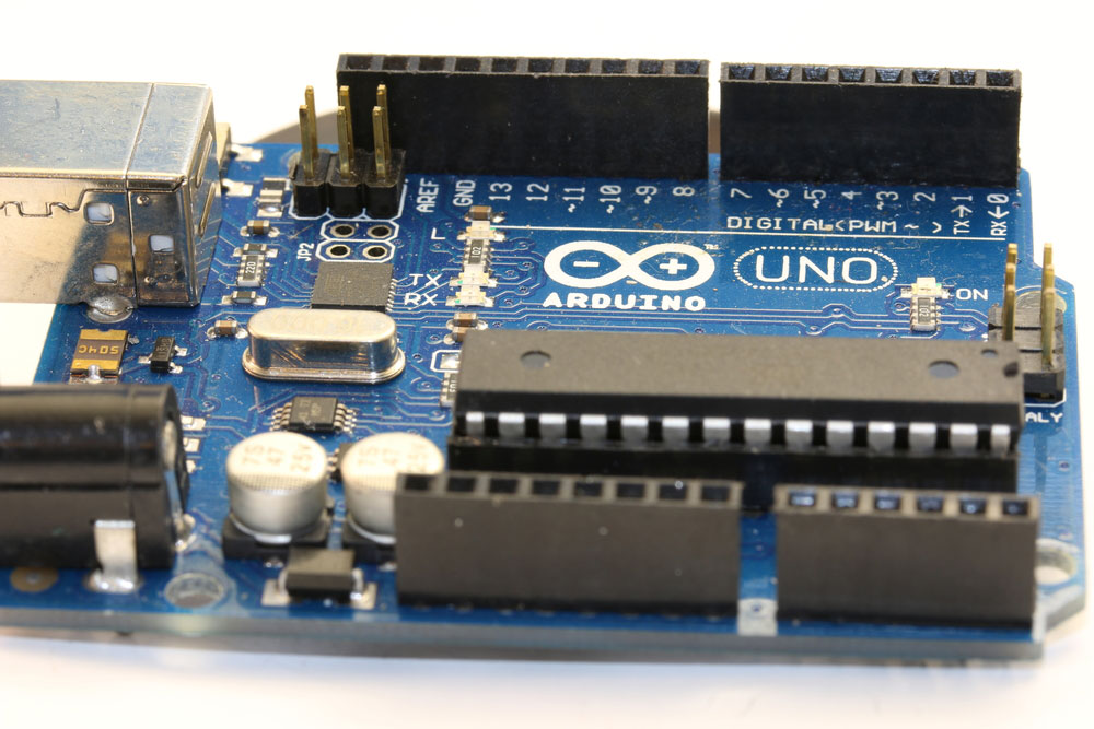
Fig 5: Arduino Uno with several electronic components
Interfacing the sound sensor with Arduino Uno is easy as you don't need a breadboard, jumper wires, or soldering.
Materials
You will need a Seeeduino/ Arduino UNO and Grove Base Shield.
Hardware configuration
- Connect the acoustic sensor to Grove's port 0/ Base shield.
- Next, connect the Seeeduino to the Grove's Base shield.
- Lastly, using a USB cable, connect the Seeeduino to a PC.
Software Configurations
- First, input this code on Arduino IDE to your Arduino UNO/Seeeduino.
- Secondly, select Serial > Plotter. You'll obtain the frequency responses when you make different sounds.
- Note: These wireless sound sensor modules are compatible with Raspberry Pi, LinkIt ONE, and BeagleBone platforms.
Sound Sensor Applications
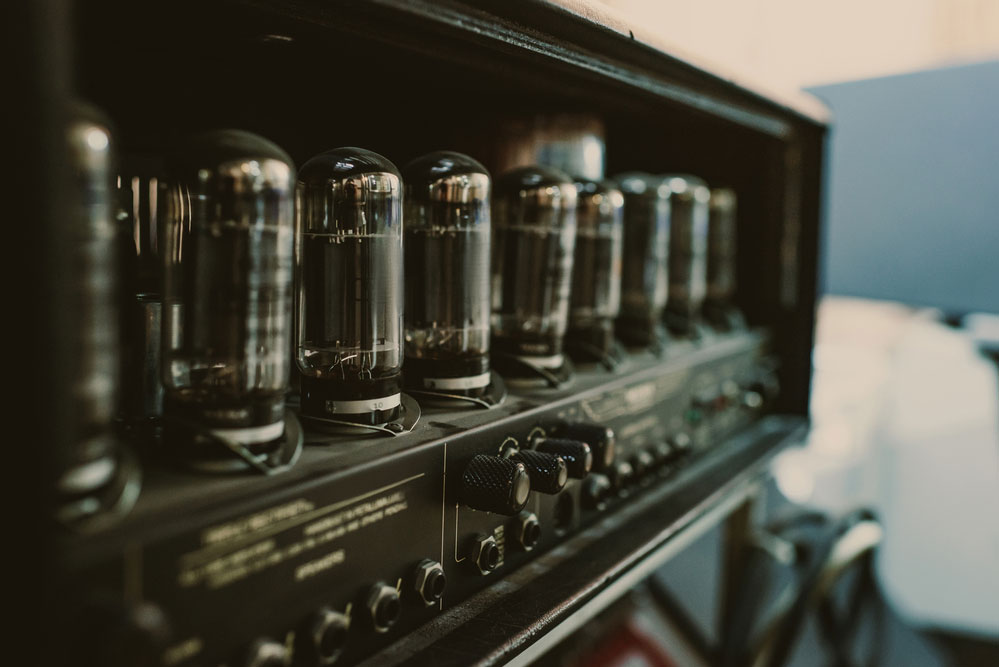
Fig 7: The sound sensor module is handy in audio amplifiers
It has a wide range of applications that include:
- Useful in spy circuits and home automation systems.
- Also, it is vital in office and home security systems.
- The module is handy in sound-level recognition systems and audio amplifiers.
- Furthermore, it's helpful in sound pressure level devices.
- Lastly, it is essential in smartphones, robotics, and ambient sound recognition systems.
Conclusion
Now you are equipped with critical insights into the sound sensor module. Also, you are now aware of its pinout, applications, and how to interface with Arduino Uno. Still, if you have queries on the module, contact us.
Special Offer: Get $100 off your order!
Email [email protected] to get started!