A current buffer amplifier circuit transforms the electrical impedance before transmitting it to the following present circuit. In this way, it ensures there's no loading of a previous course by the succeeding circuit.
It has two classifications; current buffers and an ideal voltage buffer. Current buffers with B=1 unit gain become current followers. In today's post, however, we'll major on the existing pads. In addition, we'll touch on current amplifiers and current followers.
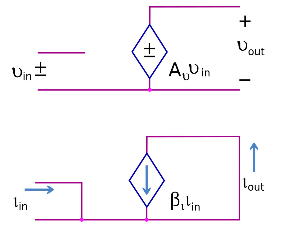
(current and voltage buffers)
Source: https://en.wikipedia.org/wiki/File:Ideal_Buffers.svg
Contents
What is a Current Follower?
A current follower, in simple terms, is a contrast of a voltage follower, and it uses two contemporary mirrors and a conventional operational amplifier.
We refer to a current buffer with a unit gain (B=1) as a recent follower or unity gain current buffer. In other words, the output current follows or tracts the input current such that there's no amplification of input signals. Consequently, the output current also doesn't increase.
They're also isolation buffers because they isolate output and input terminals while maintaining a constant input and output current flow.
Introduction to Current Amplifier
A current amplifier circuit uses a fixed factor to augment the input current signal before passing it to the subsequent electric circuit. Generally, we refer to the process as the current amplification of an input signal.
Voltage buffers and current amplifiers often share some similarities but differ in a minute aspect on current loads. Hence, you'll find that a voltage buffer keeps the output- and input-voltage the same while delivering any required load current.
Conversely, a current amplifier only allows a current of fixed multiple of an input current to the succeeding stage. It also ensures that the supply voltage component of the input signal remains unaffected.
Then, you can realize a current amplifier using transistors. Additionally, you can have an input in a time-varying waveform or as a constant signal.
Gain of a current amplifier
A gain in any electronics denotes rating an amplifier's amplifying aptitude. With a current amplifier, gain majors on the increasing rate of output signal current while considering the input signal. It's due to the current amplifier's sole altering of the input signal.
In calculation;
Gain = The magnitude of current flowing through output terminals in ratio to the extent of current of input signals.
Therefore;

The gain can either be a negative or positive value. A negative value means that the output signal is in a reversed input signal state. Further, it can be a replica of an input signal.
Characteristics of an ideal current amplifier
An ideal current amplifier should have the following characteristics to aid in its designs. They include;
- First, the amplifier's input impedance = 0.
- Then, the output impedance = infinite.
- Also, the gain of the current amplifiers should not depend on ambient conditions like humidity and temperature.
- Lastly, the current amplifiers gain = constant throughout the input signal range.
Even though it's practically impossible to achieve the recommended impedance, you can still use the values as a reference guide.
Circuit diagram
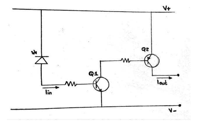
Circuit diagram of a current amplifier
From the above diagram, we can comprehend the circuit elements with the following points;
- First and foremost, the photodiode absorbs light energy then later releases electrons. The electrons are the input current source.
- Next, transistor Q1 does the first current amplification, whereas Q2 further amplifies it.
- Then, resistors at the base of the two transistors fine-tune the current gain. The number of times of signal amplifications equals the amplifier stages. Therefore, our project is of a 2-stage current amplifier since we perform two amplifications.
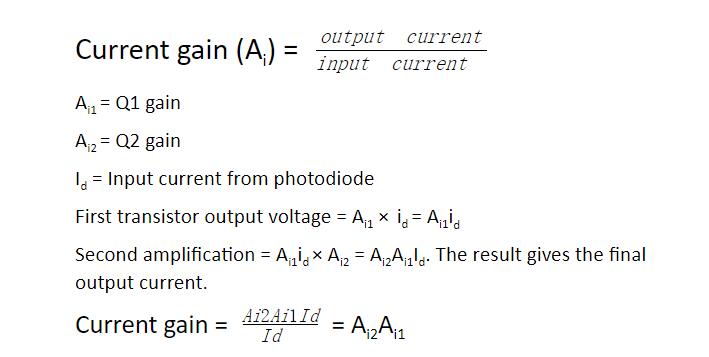
Let us now use the formula below to calculate the output current and final current gain.
Applications
Current amplifiers are applicable in a wide range of areas such as;
- In industrial manufacturing systems like in water jet cutting machines and lasers,
- The sensor systems, and
- In audio amplifier systems.
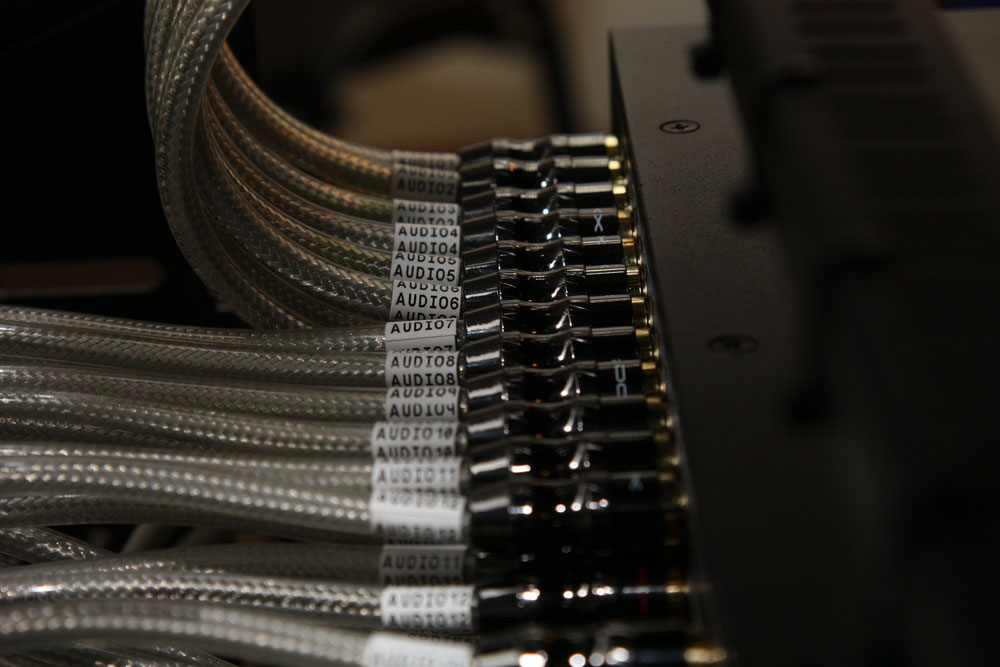
(audio amplifiers)
Special Offer: Get $100 off your order!
Email [email protected] to get started!
Introduction to Current Buffer
A current buffer circuit transfers electric currents from a course with low input impedance to a high input impedance circuit. Often, the current buffer is an intermediary amid the two circuits to avoid loading the first circuit. Further, you can use transistors such as MOSFET and BJT to realize a current buffer.
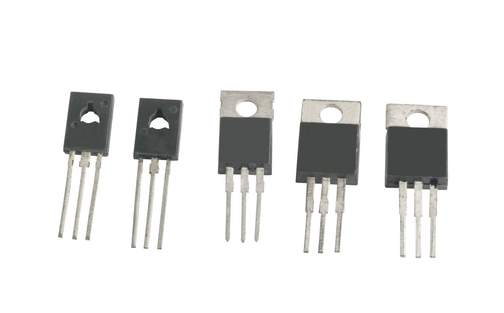
(transistor)
Current Follower Circuit-- Practical use of an existing buffer
Our practical example is a circuit that operates a robot using an LDR sensor. The robot's motors consume a current that isn't constant therefore making it dependent on the motor loads/surface roughness or inclination.
Thus, if you use a current amplifier to directly couple the motors and temperature sensors, the motor drives may have a more current draw. The current interest not only tampers with the sensor's accuracy, but it also changes voltage crossway the motors and robot's speed.
Current buffers prevent the current back by providing needed current to the motors. Additionally, it ensures the sensor's accuracy is intact and maintains a constant voltage throughout the motor terminals.
Current follower
As we had already discussed, we refer to a current buffer with a unit gain (B=1) as a recent follower or unity gain current buffer.
Circuit diagram
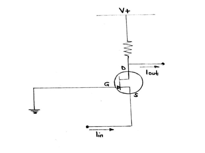
A current buffer circuit
The circuit diagram allows high impedance at the output terminal and low impedance at the input terminal. Hence, it qualifies to be a current buffer.
Current Follower Circuit-- Applications
You can use current buffers in;
- High precise sensor systems,
- Electrical actuator systems,
- Motor drives, and
- Digital logic gates.
Advantages of Current Follower Circuit
- First, it has a high and band-width.
- Also, the circuitry is stable.
- Its input impedance is low/zero, whereas the output impedance/unity current gain is infinite, therefore ideal for application. The low impedance is due to negative feedback.
How to Design a Current Follower Circuit
When you are interested in designing a current follower circuit, you should have this in mind;
- First, use an op-amp and a PNP transistor to ground the loads. You can use the diagram below for better comprehension, and the transistor is the active element here.
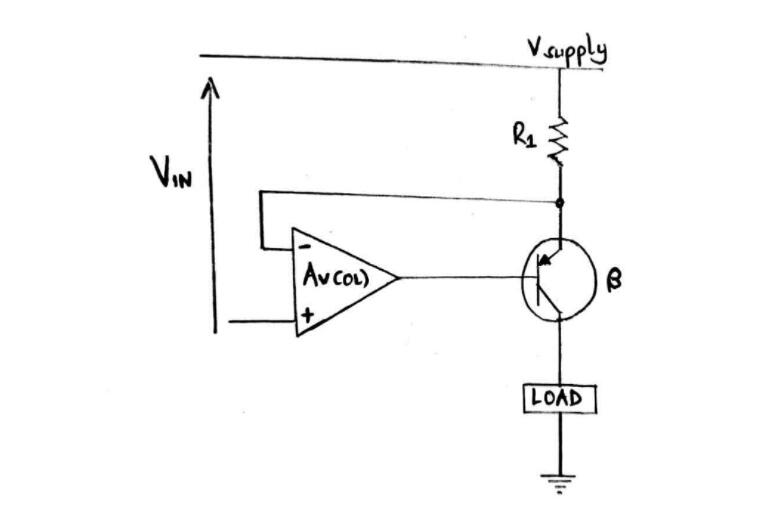
Circuit diagram with op-amp and a PNP transistor for a current follower
R1 operates as the current sense resistor. Therefore, the operational amplifier functions with its input at the supply rail of the positive voltage.
- Additionally, you can follow a current to the voltage converter with the voltage of a currency converter. It means that you'll have to choose a converter type in each place for some constraints.
For example, unipolarity, bipolarity, minimum current, floating currents, etc.
- In most constrained conditions that have unipolar currents, you can use a mirror current. Here, the voltage converter's current connects the transistor, resistor, and diode, and additional transistors can also produce better output impedances. Contrarily, the least constrained conditions will only require a differential amplifier and sense resistor with a Howland current source.
Summary
To summarize, current-buffer amplifier circuits transfer the maximum available current from a signal source to a load with non/zero-impedance. For that reason, you'll find more buffer circuits in applications that require zero input impedance, infinite output impedance, and constants gain.
We'd love to hear from you after a read. You can get in touch with us, and we'll soon get back to you.
Special Offer: Get $100 off your order!
Email [email protected] to get started!