Have you ever seen a laser beam? Lasers are commonplace in almost all industries and are of different types.
So what is the working principle and function of laser driver circuits? We’re going to provide you with an elaborate explanation of this. Also, for directions on building a circuit, read on.
Contents
The working principle of the laser diode driver circuit
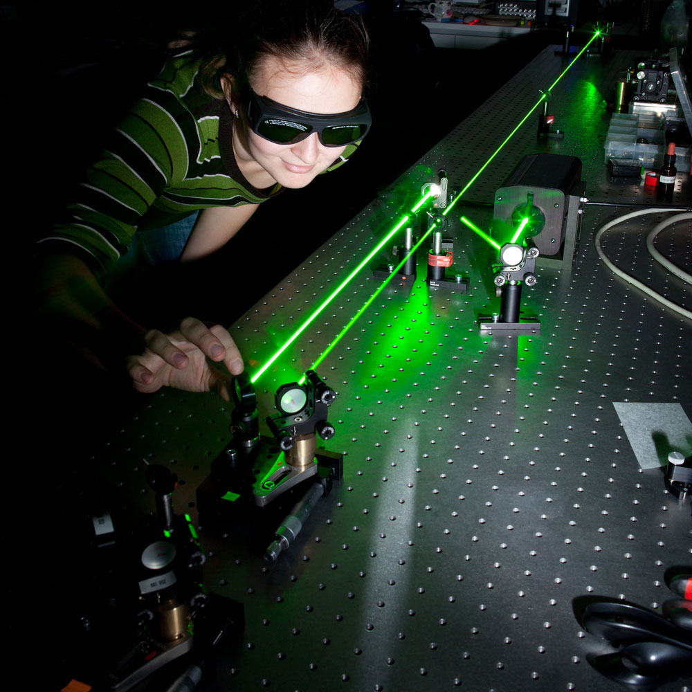
Figure 1: Two Monochromatic Laser Beams
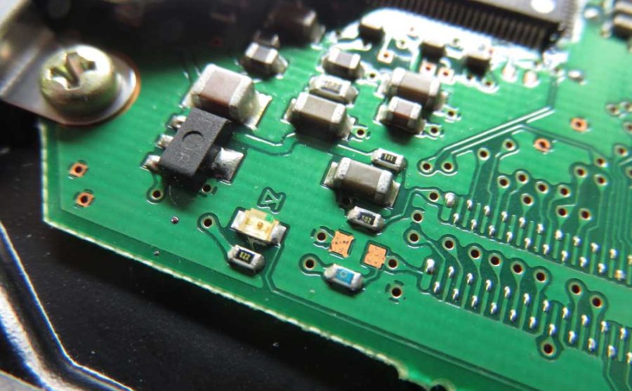
A laser diode package comprises two semiconductors in one package. On the top part of a 2-pin Laser diode, you will find a P-type semiconductor. It has a wide range of materials such as Gallium Arsenide. Its fundamental role is to receive electrons.
On the bottom of a laser diode package, there’s an N-type semiconductor. It comprises materials such as Gallium Arsenide & Selenium and has an extra electron. Hence, the two form a P-N junction. It is the basic laser diode driver source of light.
When the actual laser diode current is flowing, electrons and holes will travel towards the P-N junction. Note that electrons are negatively charged while holes are positively charged. The combination of the holes and electrons will yield a photon on the connected laser diode.
The diode lasers have to capture this photon and thus have a mirrored coating. The capture of the initial photon will encourage the combination of other holes and electrons. The result will be a yield of light photons. Note, the creation of photons will not cease until the diode junction fills with light. Subsequently, the diode D2 will emit coherent light continuously at the output stage. Just ensure that there’s a constant current supply.
Functions of a Laser Diode Circuit
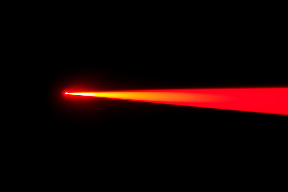
Figure 2: A Laser Beam
- A commercial laser diode is unique from other diode drivers such as Light Emitting Diode (LED). Its uniqueness is the principle property that gives functions to laser diodes in control of components.A basic form laser diode will operate on the principle of stimulated emission. Therefore, from this property, the laser diode driver circuit has several functions:
- You can use it in components that require feedback. A laser diode needs feedback, unlike a LED.
- It is helpful in the creation of unidirectional light
- You can apply it in monochromatic light applications. It doesn’t produce many colors of light.
- It is useful where you need a highly energetic light beam.
- Will provide a light beam of higher bandwidth than LED.
- You can use it where a reliable light beam source is necessary.
- It is the best source of a coherent light signal.
Special Offer: Get $100 off your order!
Email [email protected] to get started!
How to Build a Laser Diode Circuit?
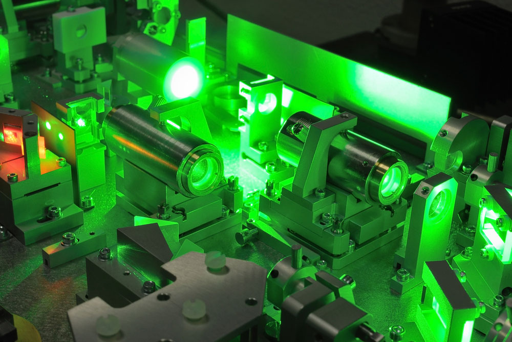
Figure 3: Several Powerful Laser Beams
First, before creating a laser diode circuit, you must have a driver circuit. Its function is to provide current protection to the laser diode. Hence, a driver circuit enforces the damage threshold of the laser diode. If you exceed the current limit setting, your laser diode will become dysfunctional. Conversely, there will be insufficient energy levels to power the laser diode with a low current level. Thus, you must provide the optimal Amp range.
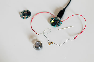
To create this driver circuit, you will need the following low price range components:
- Two external resistors- 240 Ohms and 300 Ohms
- A low capacitance ceramic capacitor of approximately 0.1µF
- A laser diode
- An LM317 Voltage Regulator IC
- A direct current power source such as AA batteries
- A heatsink
You can use a 650Nm red laser diode or any other that is available. Also, you must ensure that you include a heat sink. The voltage regulator IC will undoubtedly produce some heat. Hence, a heat sink will prove handy in thermal noise dissipation.
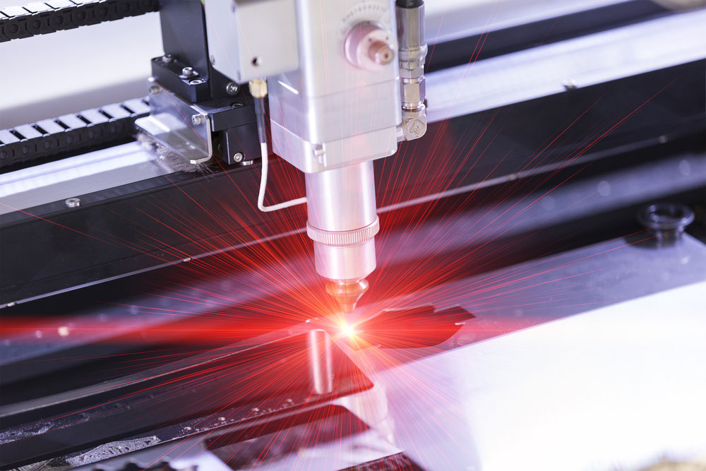
Figure 4: A Laser Beam Cutting Metal
For example, consider a case when you apply a 6V input voltage, and it regulates 3V. Thus, connect the regulator to the heat sink to control the excess voltage signal. Resultantly, you will have 3V of heat. It would help if you got rid of this thermal noise.
For this circuit, you can use a power supply voltage of between 5V to 6V. The heat sink will play the control function in limiting the impact of excess voltage. Consequently, you can use a high power supply voltage of up to 9V. Your heat sink will facilitate a voltage drop when you use a high voltage. It will, thus, control the excess thermal noise.
Also, you have to provide the right temperature range for optimal performance of the diode.
The Circuit
It is a schematic illustration of how to connect the components.
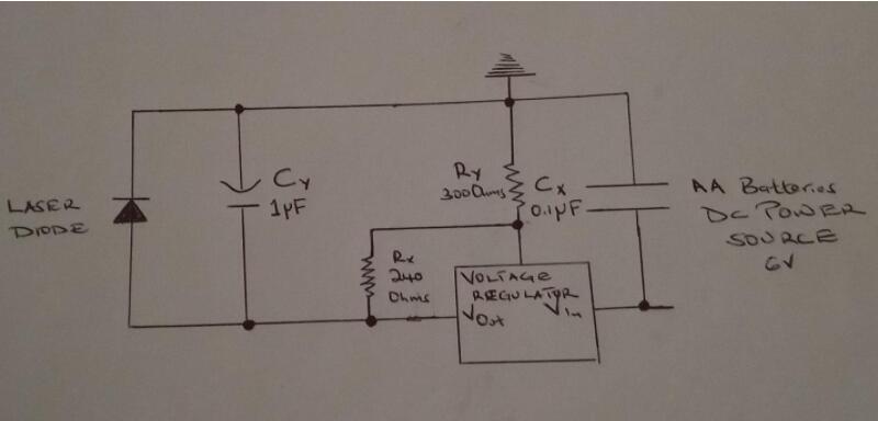
Figure 5: An illustration of a Laser Diode Driver Circuit
The capacitor Cx will filter the high-frequency noise of the power supply voltage. On the other hand, capacitor Cy will control the capacitive load. It will, thus, take care of the fluctuating signals in the circuit. Additionally, the resistors control the output voltage of the voltage regulator. Note, the choice of the resistor will determine the output voltage that you will obtain. For example, assume you want an output voltage of 3V. It would help if you chose a resistor that guarantees this.
Once you create the circuit, you need to confirm it has a suitable current limit configuration. For this, connect a multimeter in an ammeter setting between the capacitor and laser diode. The actual photodiode current that you need is approximately 20mA. Hence, your ammeter reading should be at least 20mA. You can easily control the current ranges via increasing or decreasing the resistance of the resistor, Ry. It would help if you fixed the other resistor, Rx. Therefore, you do not need to alter it.
Lastly, do not forget to control thermal noise by installing a heat sink.
Laser Diode Driver Circuit Applications

Figure 6: Laser Use in Dentistry
There is a wide range of applications where you will find this circuit. They include:
- In the telecommunication and defense sectors
- They are common in DVD and CD players
- Due to their high intensity, drillers and miners use them for drilling
- You will find them in high precision cutting instruments such as cutting metals
- Lasers have a high optical power level. Thus, doctors use them during medical operations
- They are the primary components in barcode readers
- Due to their high focus, optical fiber companies use them for signal transmission
- They are also common in most consumer electronics
- Lastly, there’s the application for demonstration purposes in schools.
Conclusion
Now we hope that you have all the critical insights into the laser diode. We have massive information on electronics and the workings of all components. Visit ourPCB site and learn more about some of the common circuits. We will always be ready to afford you any assistance that you need.
Special Offer: Get $100 off your order!
Email [email protected] to get started!