About Simple Remote-Control Circuits, Inarguably, there's an obsession with remote-control cars by kids of all ages, mostly because they are fun devices that brighten the day.
However, sometimes landing on a ready-made remote-control car can be expensive. And so, in today’s article, we are going to educate you, with an actual circuit diagram, on the simple way you can make a simple remote-control car. The car we'll design operates on radio frequency (RF) and is extremely easy to DIY. Furthermore, you won't need to program the car before using it. For further details, we will also show you how the remote-control Integrated Circuits work and explain the modules we’ll use.
Contents
Special Offer: Get $100 off your order!
Email [email protected] to get started!
How Does a Remote-Control Circuit Work?
For this project, you will fix a motor and some ICs to a chassis in making the remote-control car.
You need to get the radio frequency to transmit the control signal then have the receiver module in the car receive the input signal.
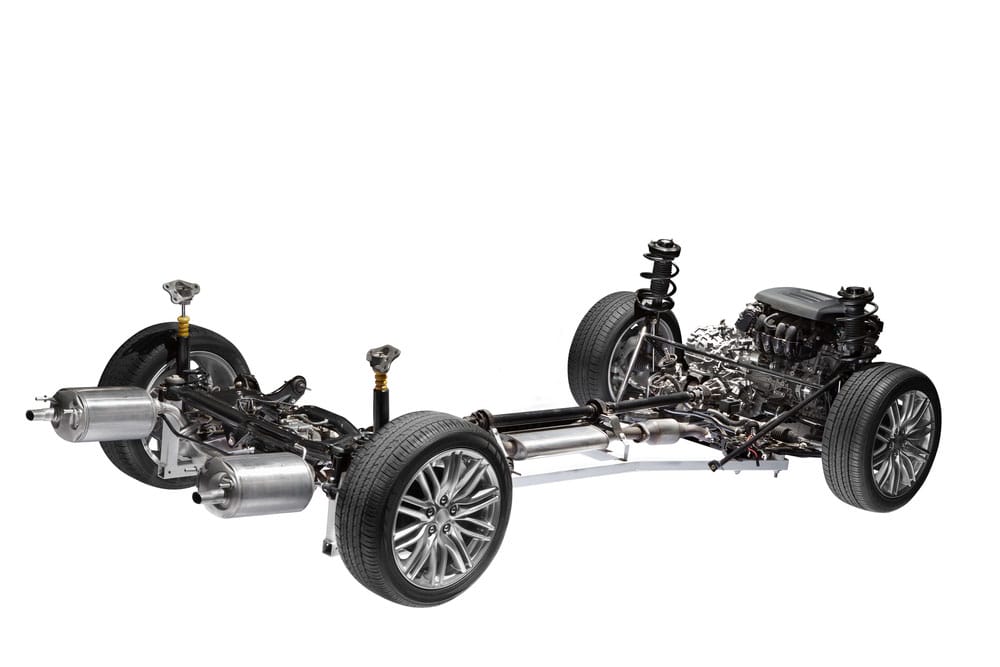
(example of a car chassis).
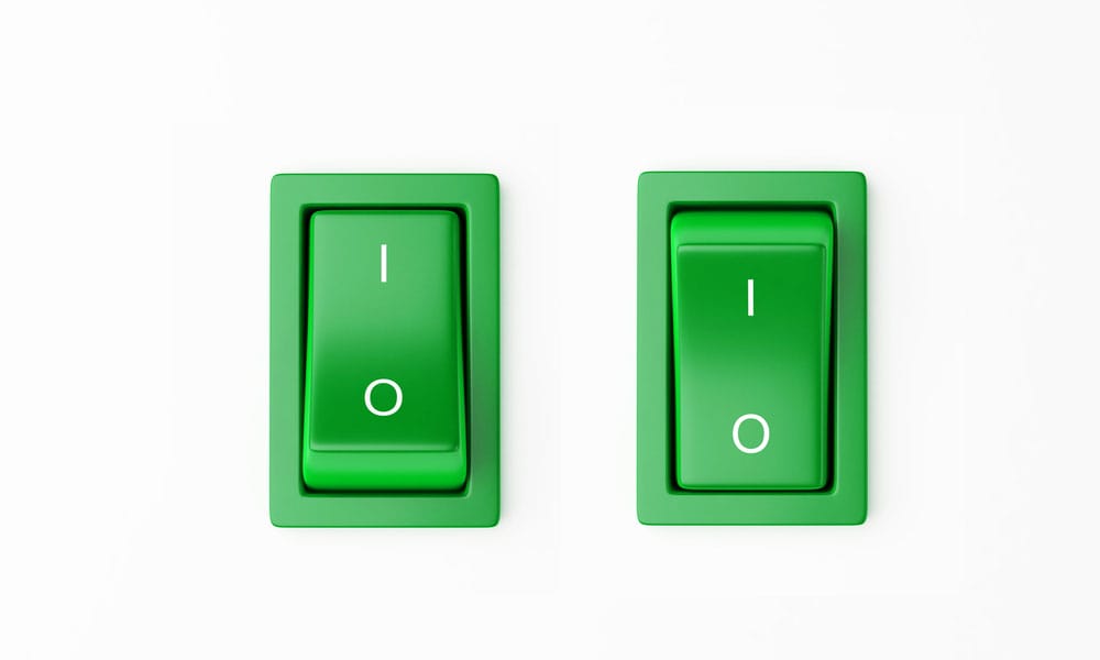
Further, the remote control has two switches, ON/OFF switches, which control data and power the car's motors.
Next, using a decoder (HT12D) encoder (HT12E) pair and an RF module, you can encode the remote control’s data before transmission, receive the data then decode it again before sending it to the motor drivers.
The ON/OFF switches’ combination additionally helps in controlling the direction your remote-control car will take. For example, the car won't move if ON/OFF switches are off since both motors won't be on in the process. Contrarily, switches on equates to turned-on motors that ultimately make the car move straight ahead.
Lastly, if you want to turn on the remote-control car, ensure you only switch on the motor on the side of the car’s turning point.
(Switch section of the electronic circuit)
How Do you Make a Radio-controlled Circuit?
First and foremost, let us consider the power supply circuit. The receiver and FR transmitter circuits will both need different power supplies. That is to say, and the transmitter circuit will work on a 9V battery, whereas a 12V supply will be enough to power up the receiver circuit.
When drawing both circuits under the RF transmitter and receiver circuit, we’ll get to see the required power supply circuit.
Alternates
- Other times, you can use a 1K resistor to add an extra LED. It will also help in showing the power supply state.
- Additionally, use IC 7805 to aid in the regulation of the 12V supply to a 5V. Due to the rapid 7V drop, it is advisable to use a heatsink because you'll experience a lot of heat production, which may burn the regulator.
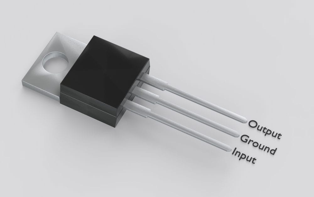
(a TO-220 MOSFET with IC 7805 pinout)
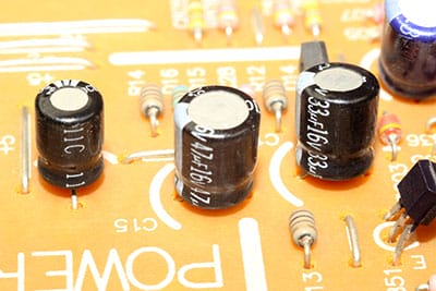
- Last but not least, also using 470uF capacitors and 0.1uF capacitors, and 1K resistors can improve the power supply.
Making the Transmitter Circuit
Materials you will need include;
- Vero circuit board,
- 2-pin terminal block,
- IC 7805,
- Push to on switch,
- Ceramic capacitor 10kpf,
- Resistor 200 ohms – 470k,
- 18- pin IC base (optional),
- Wire for antenna,
- LED,
- 433MHz rf Rx, Tx module,
- Diode 1N 4007,
- Electrolytic capacitor 100 mfd,
- 16-pin dip switch,
- Micro push-button switch, and
- HT12E.
(power switch button)
Steps in construction
- First, start by connecting IC pin 1 to 8 with the dip switch.
- Then, consider pin nine as the ground and pin 18 as the 5V supply.
- Thirdly, connect the Tx modules data pin to pin 17.
- Finally, insert all your assembled components on the Veroboard while referencing the circuit diagram below.
Transmitter Circuit Diagram
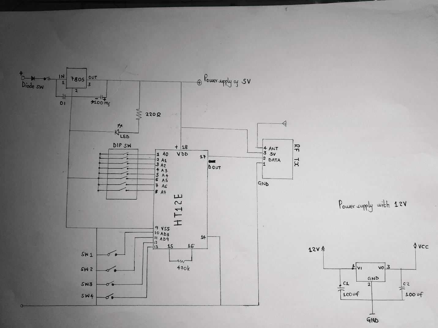
A transmitter circuit diagram
Making the Receiver Circuit
Materials/ electronic components you will need are;
- One push to on switch,
- Capacitor 10kpf, 100mfd
- 1C7805,
- 18pin IC base,
- Green LED,
- Veroboard,
- Red LED 4 pieces,
- Yellow LED,
- 2-pin terminal block,
- Resistor 220 ohm 6 pieces-46k,
- Diode 1N4007,
- 16 pin dip switches,
- Header pin,
- Wire for antenna, and
- 433 MHz rf receiver module.
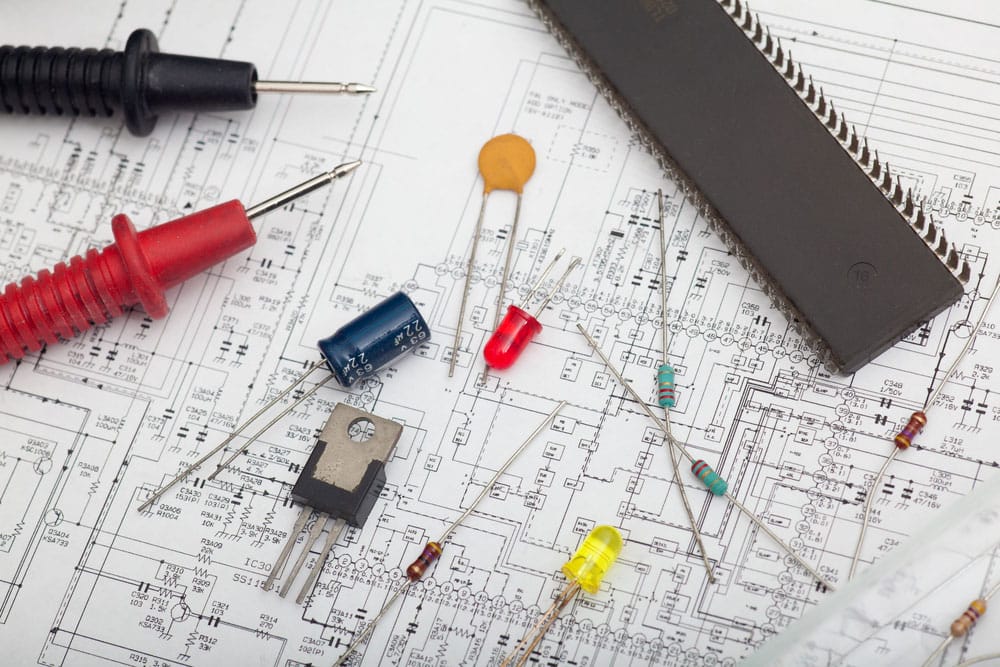
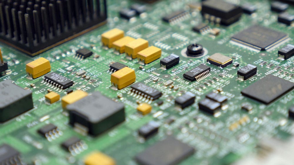
(Various electronic components)
Steps in construction
- Begin by connecting IC pin one to eight to the dip switch.
- Next, connect 5V and 9V to pin 18.
- After that, connect pin 14 to the rf receiver module (the data pin).
- Lastly, insert all the receiver components on the circuit board, and connect them as per the circuit diagram below.
Receiver Circuit Diagram

Note; use an antenna, such as a telescopic antenna, for both circuits. Also, notice that the transmitter uses an HT12E encoder, whereas the receiver uses an HT12D decoder.
Most importantly, use black wires for -ve and red for +ve. In case a problem arises, the colors will help you figure it out fast.
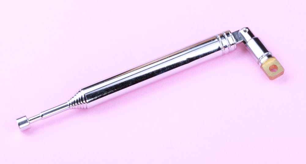
(a telescopic antenna).
Choosing the Right Motor
Choosing the best car motor will often depend on the robot car type you're planning on using. And so, for a large car, you can use a 12V DC motor since it will carry a heavy load. As for the smaller one, a 6V Bo motor should be enough.
Choosing the right rpm for the motor
Revolutions per minute (RPM) refers to the number of times the DC motor’s shaft will spin completely per minute. That is a spin cycle of 360° turn. While choosing your motor for the project, settle for a low RPM because they are easier to control. Take the instance in this project where we have used a 12V 300RPM, which is manageable. Also, remember that torque is inversely proportional to motor speed.
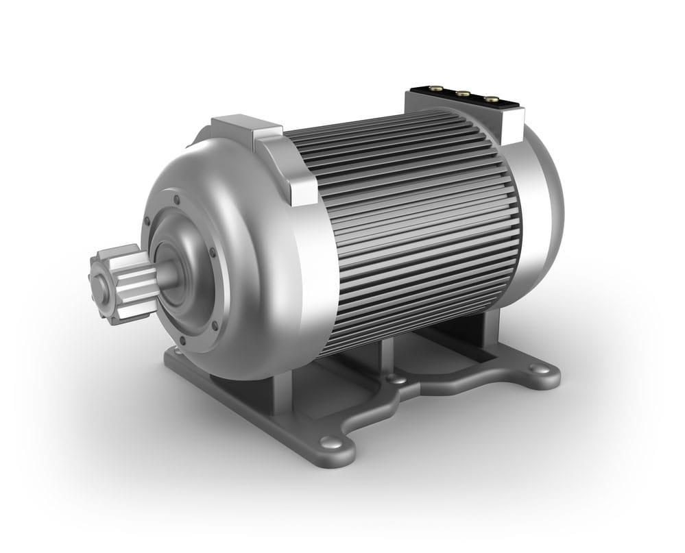
(Electric motor)
Debugging the RC Car
Debugging your remote-control car will only be necessary if you experience some challenges in the circuit.
For clarity purposes, we will explain the debugging in two different parts of the circuit.
In Power Supply
More often than not, short circuits contribute to power supply problems. To rectify the power problem, start by powering off the car's circuit. Then using a multimeter, check for a connection between the positive and negative wires.
Encoder and Decoder are debugging.
When debugging the encoder and decoder IC;
- First, connect pin 14 of HT12D to pin 7 of HT12E.
- Then, connect 4 LEDs at pins 10, 11, 12, 13 of HT12D. Also, connect push buttons at pin 10, 11, 12, 13 of the encoder.
- Afterward, press the switches to test if the LEDs work. However, if they don't light up, check the RF module and replace it.
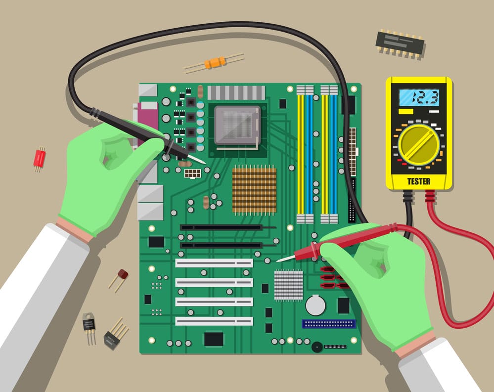
(Engineer detects motherboard)
Conclusion
That's it! We have successfully set up our remote-control car. We assure you, if you diligently follow the guideline above, there’s a chance you’ll get the DIY perfectly done on time. If, however, some concepts are still unclear, contact us, and we are at your service.
Special Offer: Get $100 off your order!
Email [email protected] to get started!