An electric circuit typically performs certain functions based on the components’ overall configuration. In that case, only two arrangements exist for this purpose: a series and a parallel circuit. This article focuses on the simple parallel circuit, which supplies an equal amount of current to each component. Generally, you will discover that it features pathways for the branch current flow, serving as a useful solution for any intended application.
This article will help you better understand a parallel circuit and how to find the necessary values for the components. So let’s take a look!
Contents
- What is a Parallel Circuit?
- How to Make a Parallel Circuit?
- Ohm's Law Applications for Simple Parallel Circuits
- Three Laws of a Parallel Circuit
- Voltage in Parallel Circuits
- Current in Parallel Circuits
- Resistance in Parallel Circuits
- Differences & Similarities Between a Parallel Circuit & a Series Circuit
- Simple Parallel Circuit Examples
- Parallel LED Circuit
- Parallel Transistor
- Parallel RLC Circuit
- Parallel Battery Bank
- Parallel Connected Capacitors
- Fault in Parallel Circuits
- Summary
What is a Parallel Circuit?
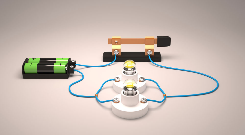
3D rendering of a parallel circuit with light bulbs.
A parallel circuit is a circuit in which the current moves through multiple paths. Generally, this also features components that form a connection to each lead. In addition, each component relies on just one shared voltage. You can also refer to each path as a parallel branch, which splits the current to pass a portion onto the next branch. All parallel circuits feature two sets of electrically common points.
These circuit types have common applications in car headlights, electrical equipment, houses, and many more.
How to Make a Parallel Circuit?
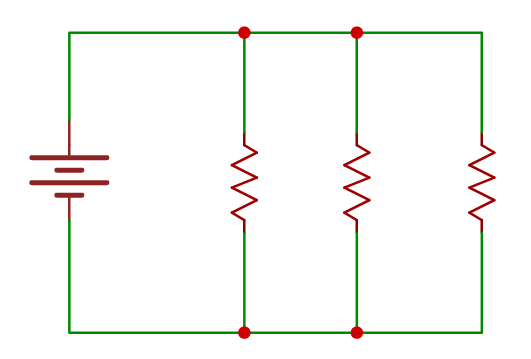
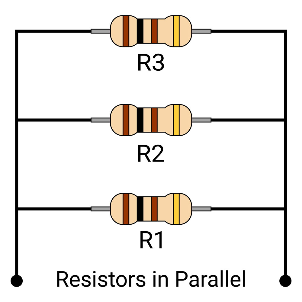
Parallel resistor circuit diagram.
To create a parallel circuit, you must connect multiple electronic components across the same voltage source. In the circuit diagram, the individual resistors (R1, R2, and R3) connect parallel to the other. Additionally, all leads of the resistors form a connection with the supply voltage (single battery).
Ohm's Law Applications for Simple Parallel Circuits
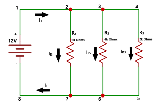
Circuit diagram showing current flow.
Apply Ohm’s Law to calculate the voltage, current, and resistance values. The circuit above already provides values for the voltage across each resistor (12V) and resistance. So you can reference Ohm’s Law to find the current instead.
However, you will need to calculate the total circuit current without Ohm’s Law. To find that number, add all values of the resistor currents together. 
While flowing throughout the circuit, the total current will separate after reaching the second point. And this allows it to pass through R1 until splitting up at point three. From there, it will pass through R2 while R3 receives the rest. Overall, this works like a current divider.
 Each resistor must have the same current flow rate.
However, each resistor’s current flow rate must match the circuit’s total flow rate. In that case, the current flow traveling from point 7 to point 8 must have a similar value to the R1, R2, and R3 currents.
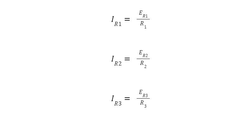
Therefore, you can apply this approach to calculate the total current for IR1, IR2, and IR3.
Special Offer: Get $100 off your order!
Email [email protected] to get started!
Three Laws of a Parallel Circuit
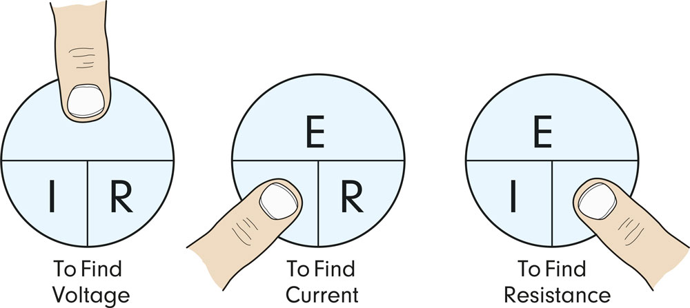 Applying Ohm’s law to find the voltage, current, and resistance values.
When creating a parallel circuit, you will need to follow the three laws. These help determine the correct voltage, current, and resistance values.
-
Voltage in Parallel Circuits
A parallel circuit’s source voltage will equal the voltage rating across the components. That occurs due to the parallel circuit, as shown above, containing two sets of nodes. So the voltage from one point to the other never changes at any time. In that case, the voltage level across R1 matches R2, which equals R3. The battery’s voltage also remains the same in this context.
The following table represents the voltage values for the parallel circuit:

Therefore, R1 = R2 = R3 = VS (12V Battery).
-
Current in Parallel Circuits
Multiple pathways on a parallel circuit.
As you know, a parallel circuit provides more than one current flow path. You can determine this based on how many components form a parallel connection. Use the following equation to find the total current:
IT = I1 + I2 + I3
However, you must apply Ohm’s Law to find the value of each resistor’s current.

IT = 2A + 3A + 6A = 11 A

-
Resistance in Parallel Circuits
Lastly, the formula below will determine the total circuit resistance value:

Thus, you can now complete the table as follows:
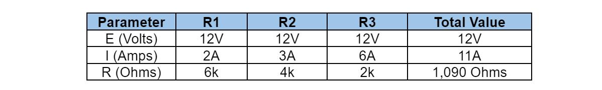
Additional individual resistances decrease the overall resistance. The parallel circuit has a total resistance value (1,090 Ohms) less than each resistor.
Differences & Similarities Between a Parallel Circuit & a Series Circuit
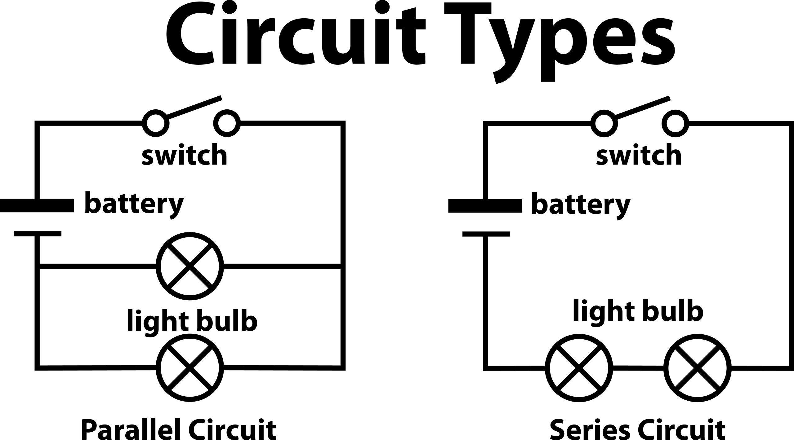 Differences between a parallel and series circuit.
As you can see in the table below, a parallel circuit differs in comparison to a series circuit. 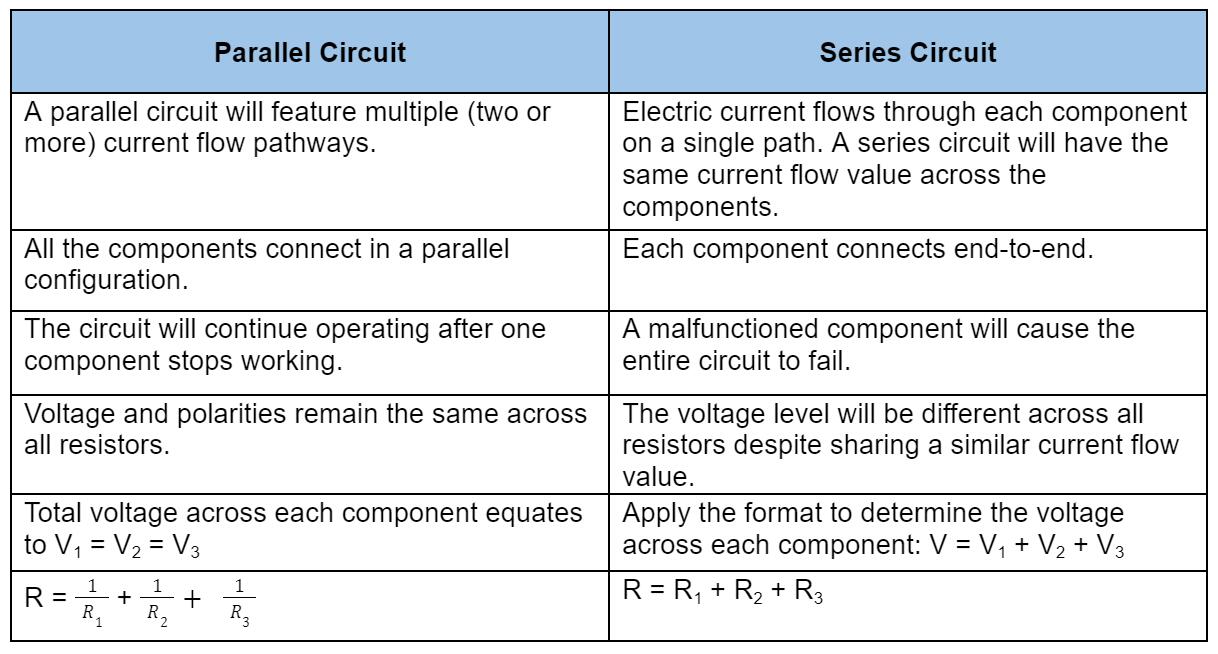
Simple Parallel Circuit Examples
We included five parallel circuit examples below, which provide different capabilities.
-
Parallel LED Circuit
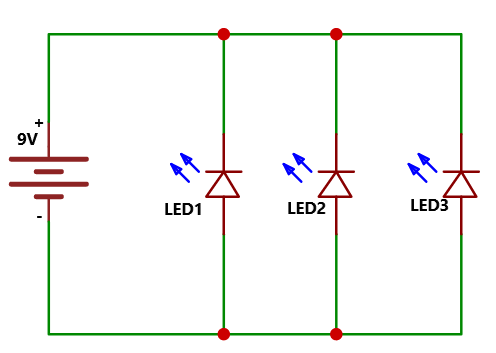
Apart from resistors, you can also connect multiple LEDs in parallel. If an individual LED stops functioning in this circuit, the others will still illuminate. However, this may require more current compared to a series LED circuit.
-
Parallel Transistor
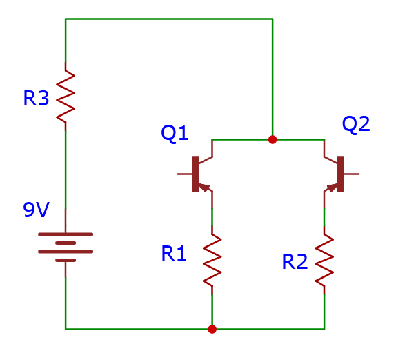
Transistors connect in parallel for high current handling. These require approximate ratings to share the same current. You can achieve this by connecting resistors in series, as shown in the circuit diagram.
-
Parallel RLC Circuit
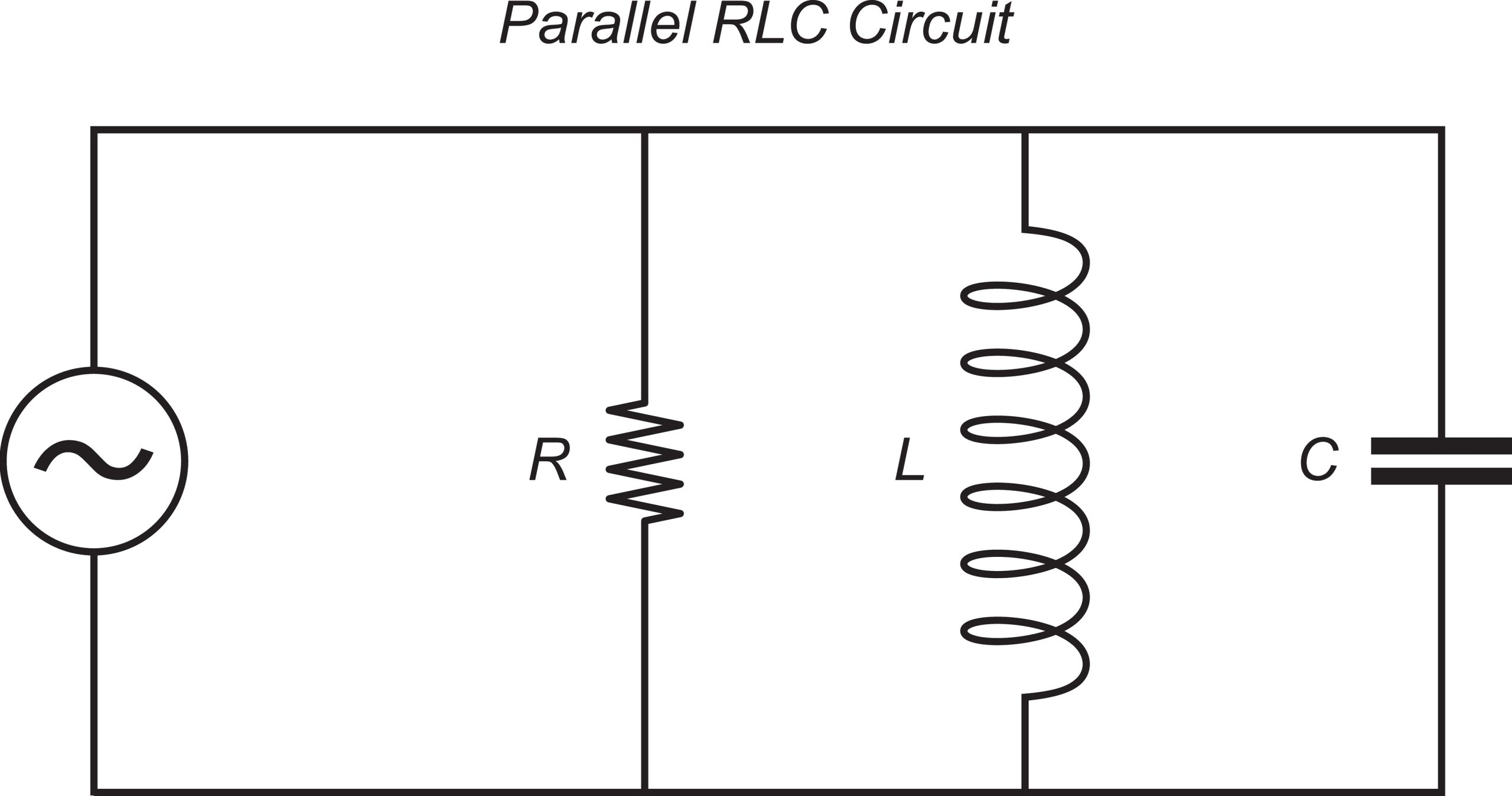 Parallel RLC circuit diagram
Integrating capacitors, resistors, and inductors in a parallel circuit may present varying performance capabilities. For example, the parallel RLC circuit can work as a frequency tuning and filter circuit along with oscillator circuits.
-
Parallel Battery Bank
You can connect three DC batteries in parallel, which will serve as a power bank circuit. In this case, each 18650 3.7V, 3000mAh battery increases the overall capacity. Thus, the new rating sets to 3.7V/9000mAh when connected in parallel.
-
Parallel Connected Capacitors
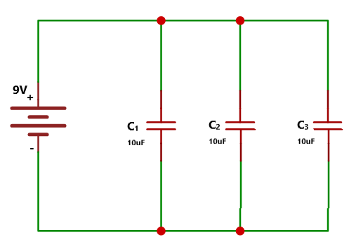
Ultimately, parallel connected capacitors will boost the overall capacitance in a circuit. Each 10uF individual capacitor forming a parallel connection will produce an overall capacitance of 30uF.
Fault in Parallel Circuits
Two faults may affect the performance. Each example will have three resistors.
- Open Circuit:
If one resistor fails on a circuit, then the current will still flow through the other two resistors. It will not affect performance since the voltage remains the same.
- Short Circuit
A short circuit will cause a voltage drop level to reach zero in each resistor. Afterward, the shorted resistor will have maximum current flow. Meanwhile, the others won’t have any current flow.
Summary
Overall, parallel circuits can prove advantageous for any project. If an electronic component connected in parallel suddenly dies, the rest will continue operating. The current will always flow throughout the circuit while it runs. Simple applications, such as computer hardware, and DC power supplies, have parallel circuits. These ensure optimal performance as well. However, the design process might be more complex and expensive for large projects. So those drawbacks may otherwise make it difficult to choose a parallel circuit configuration.
Do you have any questions regarding the parallel circuits? Feel free to contact ourPCB!
Special Offer: Get $100 off your order!
Email [email protected] to get started!